Not a kit!
Nobody who is old enough to have assembled a Heathkit with its almost perfect instruction book would call the Boyuu and similar amps a 'kit'.
It's a box of parts and a PCB, and you need some skill and experience to put it together and get it working properly without issues.
Nowadays, beginners really have to 'jump into the deep end' to get started building projects - it's definitely a challenge. Add in the desire to 'make it better with mods' and it's even more of a challenge.
I built a similar Chinese kit some years ago and it is still working just fine.
Luckily beginners have many many pages of reading resources for the Boyuu here at diyaudio!")
Nobody who is old enough to have assembled a Heathkit with its almost perfect instruction book would call the Boyuu and similar amps a 'kit'.
It's a box of parts and a PCB, and you need some skill and experience to put it together and get it working properly without issues.
Nowadays, beginners really have to 'jump into the deep end' to get started building projects - it's definitely a challenge. Add in the desire to 'make it better with mods' and it's even more of a challenge.
I built a similar Chinese kit some years ago and it is still working just fine.
Luckily beginners have many many pages of reading resources for the Boyuu here at diyaudio!
I was also very active in this forum but I stopped after I got my amp to a point where I liked (my last post was #985 on June 2nd, 2019). So now I'm just enjoying the amp. No more mods.
I agree with the previous posts that building this amp requires experience and previous knowledge of electronics. I had extensive knowledge of electronics (transistors and IC's) but I had to learn about tubes. It was an extremely fun experience building this amp and to me the best part was that it got my brain to work again with basic and advanced electronics calculations. Things people don’t do anymore. Computers do it for us now.
I do encourage people to take the challenge and build this amp but do your homework and learn as much as you can about electronics and amps, and practice good soldering before starting this project. As I said, it’s a fun and rewarding project so don’t let it became a bad experience and big frustration because you didn’t prepare before staring it. Also, be careful with high voltages inside the amp. Safety is very important with working with tubes.
That said, I’m really happy with the mods I made because I was able to get a better frequency response and about 30% more power than the original design (and it was fun doing the mods too). My amp sounds very good and I'm happy with it. I’m attaching the graphics so you can see.


Overlapped curves used for comparison

BTW, I was using sine wave signal during these measurements but I read many times in this forum about testing with square wave signal. Why is square wave is better than sine wave for tube amp tests? Will the results be much different than the results with sine wave? Again, I’m still learning about tube amps and this will add to my knowledge.
As you can case in the diagram, I did a lot of modifications compared to the original design but I did because I wanted to "experiment and learn". Most of people will not need to modify this much, but I was having fun so kept doing it. Besides the circuit modifications, I replaced the 6SL7 and the EL34 tubes with JJ tubes and replaces the potentiometer and the power switch with better quality ones. Even if you don't modify the circuit, I think replacing these components will improve the performance of your amp. I did not modify the rectifying circuit expect for adding the 2 resistors to filament wire to remove hum.

At the end, I've also added the VU's to make it more vintage look and because I love to watch the needles moving with the music. But this requires some precise metal work so I only recommend it to a very experienced metal work person.

This forum has been crucial for me to learn about tube amps and I thank all of you for the contribution and share of knowledge.
Cheers.
Fdlima
I agree with the previous posts that building this amp requires experience and previous knowledge of electronics. I had extensive knowledge of electronics (transistors and IC's) but I had to learn about tubes. It was an extremely fun experience building this amp and to me the best part was that it got my brain to work again with basic and advanced electronics calculations. Things people don’t do anymore. Computers do it for us now.
I do encourage people to take the challenge and build this amp but do your homework and learn as much as you can about electronics and amps, and practice good soldering before starting this project. As I said, it’s a fun and rewarding project so don’t let it became a bad experience and big frustration because you didn’t prepare before staring it. Also, be careful with high voltages inside the amp. Safety is very important with working with tubes.
That said, I’m really happy with the mods I made because I was able to get a better frequency response and about 30% more power than the original design (and it was fun doing the mods too). My amp sounds very good and I'm happy with it. I’m attaching the graphics so you can see.
Overlapped curves used for comparison
BTW, I was using sine wave signal during these measurements but I read many times in this forum about testing with square wave signal. Why is square wave is better than sine wave for tube amp tests? Will the results be much different than the results with sine wave? Again, I’m still learning about tube amps and this will add to my knowledge.
As you can case in the diagram, I did a lot of modifications compared to the original design but I did because I wanted to "experiment and learn". Most of people will not need to modify this much, but I was having fun so kept doing it. Besides the circuit modifications, I replaced the 6SL7 and the EL34 tubes with JJ tubes and replaces the potentiometer and the power switch with better quality ones. Even if you don't modify the circuit, I think replacing these components will improve the performance of your amp. I did not modify the rectifying circuit expect for adding the 2 resistors to filament wire to remove hum.
At the end, I've also added the VU's to make it more vintage look and because I love to watch the needles moving with the music. But this requires some precise metal work so I only recommend it to a very experienced metal work person.
This forum has been crucial for me to learn about tube amps and I thank all of you for the contribution and share of knowledge.
Cheers.
Fdlima
Last edited:
Fdlima,
Wow!
That is the first time on this thread I have seen the input circuit schematic drawn correctly.
And that is the proper way to use a parallel input tube.
Most schematics do not connect pin 4 from the right side, they just connect between the grids in the middle, and so can not have individual grid stoppers.
And so many do not go to the recommended trouble to have individual: bias resistors and bypass caps.
Some have even not connected pin 4 at all, because of all the incorrect schematics out there, and for those who hand wire a copy, rather than have a version that has the PCB.
Hello 6A3sUMMER, I registered on this site in December 2019. I browsed all the pages of this thread to have enough information to wire the boyuu A9. This is the first tube amp I build and I was able to get it working without any problems. I have no in-depth knowledge of electronics and tubes. However I am not entirely satisfied because I still have a slight buzz in the speakers. I could see on this amp that the terminal 7 of the 6n9p is wired to the ground of the pcb as well as the terminal 2 of the el 34. do you think that if I replace these connections by resistances of 100 ohms to the mass of the chassis as explained in thread that it will decrease the hum?
I do not see the power supply schematic. But . . .
The 6SL7 pins 7 and 8 are the filaments, and the EL34 pins 2 and 7 are the filaments.
I believe all these pins tie two just one filament secondary.
Use two each 100 Ohm resistors. Tie ground at one end of both resistors, and tie the other leads of the resistors, one to pin 7 and the other to pin 8 of the 6SL7.
That is a filament secondary Pseudo center tap to ground.
You may have ground loops or wiring placement that causes hum.
If you have more hum in one channel than the other channel, check to see if the one that has more hum is the one that has the B+ choke under that channels output transformer.
I do not see the power supply schematic. But . . .
The 6SL7 pins 7 and 8 are the filaments, and the EL34 pins 2 and 7 are the filaments.
I believe all these pins tie two just one filament secondary.
Use two each 100 Ohm resistors. Tie ground at one end of both resistors, and tie the other leads of the resistors, one to pin 7 and the other to pin 8 of the 6SL7.
That is a filament secondary Pseudo center tap to ground.
You may have ground loops or wiring placement that causes hum.
If you have more hum in one channel than the other channel, check to see if the one that has more hum is the one that has the B+ choke under that channels output transformer.
First of all, a big thank you for your advice. I'm going to order 3W / 100 ohm resistors and see what happens. There is one channel that has more hum than the other but it is the right channel but it is not that of the starter B +. I wish it was this one. To give you an idea of my wiring of the masses, I posted a message (# 1078) with pictures. if that can give you ideas. See you soon.
learn you only need 1/2 watt resistors. the current is VERY small
Yes you are right. Sometimes I'm a little stupid.
I was thinking of the el34 tubes but as the resistors will be used for the preamplification tubes, 3w is clearly oversized.
learn,
Both the 6SL7 and EL34 use 6.3V filaments.
The 100 Ohm resistors are connected in series across the 6.3V.
6.3V / 200 Ohms = 0.0315A (31.5 mA).
6.3 V x 0.0315 A = 0.2 Watts Each resistor dissipates 0.1 Watt
5 times that gives good margin (0.5W).
It is true that the mid point of the series resistors has to handle a very small additional current.
The mid point of the series resistors are connected to ground. The "extra" current is the very small noise current that you are returning to ground through the two 100 Ohm resistors.
If the 6SL7 and EL34 tubes are powered by separate filament secondaries, the same size resistors would be used for each 6.3V supply.
But the 6SL7 grids are more sensitive to any noise that is on the filament wiring, especially if it is close to the grid wiring and parts in the grid circuit.
Last edited:
learn,
Both the 6SL7 and EL34 use 6.3V filaments.
The 100 Ohm resistors are connected in series across the 6.3V.
6.3V / 200 Ohms = 0.0315A (31.5 mA).
6.3 V x 0.0315 A = 0.2 Watts Each resistor dissipates 0.1 Watt
5 times that gives good margin (0.5W).
It is true that the mid point of the series resistors has to handle a very small additional current.
The mid point of the series resistors are connected to ground. The "extra" current is the very small noise current that you are returning to ground through the two 100 Ohm resistors.
If the 6SL7 and EL34 tubes are powered by separate filament secondaries, the same size resistors would be used for each 6.3V supply.
But the 6SL7 grids are more sensitive to any noise that is on the filament wiring, especially if it is close to the grid wiring and parts in the grid circuit.
Well. Your explanations are clear. I will use 1 / 2W resistors. Thank you so much.

Fdlima,
Wow!
That is the first time on this thread I have seen the input circuit schematic drawn correctly.
And that is the proper way to use a parallel input tube.
Hi 6A3sUMMER,
Thanks for the complements. This project was like a "therapy" for me so I took the time to do it right. You do more when you're having fun.
Do you, or anybody in the forum, have a explanation why to use a square wave signal input than with sine wave signal for the tests?
Thanks,
Lima
Generalizations:
For these tests, you need a scope with FFT, or scope and spectrum analyzer.
A pure sine wave allows for testing of harmonic distortion, and with an adjustable frequency range allows you to test frequency response.
You can also test for output power, including seeing at what point clipping occurs.
Two sine waves of different frequencies allows Intermodulation distortion testing.
If you have a simple scope, if the amp is not too good, you can see it in the time domain.
If you have a spectrum analyzer, or an FFT, you can test all of these to a lower level that can not be seen in the time domain.
A square wave can be used for tests of rise time, fall time, low frequency tilt, overshoot, and "ringing".
Thanks for the explanation.
I have a Hitachi V660 analogue oscilloscope but I don't have a spectrum analyzer. I'll try the tests with a square wave to see the results.
Cheers,
FLima
I have a Hitachi V660 analogue oscilloscope but I don't have a spectrum analyzer. I'll try the tests with a square wave to see the results.
Cheers,
FLima
Thank you
Thank you for your message of support. I also hope for the best for everyone because we are all going through difficult times.
Hi All,
These are difficult times for everybody, so I just wanted to wish the best to all of you and your loved ones.
Stay safe and let's use this time we're now stuck at home to enjoy the wonderful sound coming out of our A9 tube amp.
Stay safe.
Frank
Thank you for your message of support. I also hope for the best for everyone because we are all going through difficult times.
Hi All, I hope everybody is doing well.
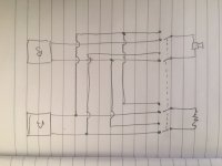
I’m using my “stay at home” time to build a speaker selector box so I can easily switch my speakers to play from the A9 Tube amp or from my Sansui receiver, but I have a technical question that I would like the experts in this group to give me some advices regarding the wiring of the speaker switch.
The first diagram shows the correct and ideal way to wire the switches between the amps, i.e.: Switch the positive speaker wire, switch the negative speaker wire and switch on the 8ohms load resistor when tube amp is not selected. But the problem with that is that I will need a 2 pos x 6 poles switch, which I don’t have.
I would like to use a very nice 2 pos x 4 poles speaker switch that I have here so I would like your advice on if I can connect the negative speaker wires of both amps, as shown in diagram 2?
Will this cause any problems? My main concern is if I will have ground loop between the amps since the RCA cables are connecting the grounds of the two amps and now the negative speaker wires will also connect the grounds of the two amps.
Notes:
The diagrams show internal ground connections.
The diagrams show only one channel.
A9 Tube amp has the 3 prong AC receptacle with ground connected to chassis and circuit ground.
Sansui receiver has the 2 prong AC cord without ground.
BTW, I use my Sansui receiver as a pre-amp/tone control/source selector to the A9 Tube amp. And sometimes I like to hear the music directly from the receiver.
Thanks in advance for your help.
Fdlima
I think that assuming ground is shared is unsafe. The tube amp is relying on ground and earth being treated seperately as a safety measure, and you also never know how different circuits in the house could be wired - in my house they could be different phases.
I wanted to do something similar, and in the end just made sure I had banana plugs on the speaker cables so they could be easily switched.
The risk to your tube amp is that it is playing at high volume when switched, and the transient created when switching to the temp load causes a spike in the OPT.
One option that I intend to use from now on is to keep a 400 ohm resistor wired across the speaker out connection on the tube amp, so that there is never an open circuit on the output.
Is there anything wrong with having the 8 ohm load alternated between tube amp and SS amp ? Then a 4 pole switch should be ok?
Hi OldHector,
How about the old simple rule of turning off the amplifier before messing with the speaker leads??? Even on my test bench, for tube amps I do not disconnect the speaker leads unless the amplifier is off. That's even to switch between the dummy loads and the bench speakers.
For transistor amps, if it has speaker switches I use those, otherwise the amp goes off to play with speaker leads - and I use speak-on connectors to connect to loads (so no danger of shorts).
-Chris
I think that assuming ground is shared is unsafe...
Hi OldHector. Thanks for the response.
“The tube amp is relying on ground and earth being treated separately as a safety measure”
[FL] You are correct. The ground and earth are separate inside the tube amp. I have revised the drawings to show that.
“and you also never know how different circuits in the house could be wired - in my house they could be different phases.”
[FL] Here in the United States AC wiring is very standard with one wire been NEUTRAL and the other wire been HOT (110V). and the AC plugs prongs have different sizes, so they only go one way, thus it’s very hard to have the different phases throughout the house.
“The risk to your tube amp is that it is playing at high volume when switched, and the transient created when switching to the temp load causes a spike in the OPT.
One option that I intend to use from now on is to keep a 400 ohm resistor wired across the speaker out connection on the tube amp, so that there is never an open circuit on the output.”
[FL] Good advice. I didn’t thing about that.
“Is there anything wrong with having the 8 ohm load alternated between tube amp and SS amp ? Then a 4 pole switch should be ok?”
[FL] If it is as shown in your diagram in the post above, to wire in stereo I will need an 8 pole switch
. Cheers,
Fdlima


- Home
- Amplifiers
- Tubes / Valves
- Boyuu EL34 A9 Tube Amp