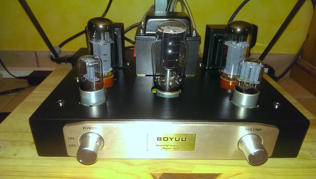
Wilkij
Hi, I've had one of the kits since early last month but was a bit wary of starting construction due to the basic instructions. A very long and tiring story cut short, I emailed through ebay to Doukstore in China for more info with no result so it went on the back burner until I came across this forum. Started construction having read all 9 pages and finished it last night.checked the wiring 3 times, connected speakers switched it on and promptly smelled burning! Found that three resistors(R 301/303) had started to cook, any ideas?
Hi, I've had one of the kits since early last month but was a bit wary of starting construction due to the basic instructions. A very long and tiring story cut short, I emailed through ebay to Doukstore in China for more info with no result so it went on the back burner until I came across this forum. Started construction having read all 9 pages and finished it last night.checked the wiring 3 times, connected speakers switched it on and promptly smelled burning! Found that three resistors(R 301/303) had started to cook, any ideas?
Started construction having read all 9 pages and finished it last night.checked the wiring 3 times, connected speakers switched it on and promptly smelled burning! Found that three resistors(R 301/303) had started to cook, any ideas?
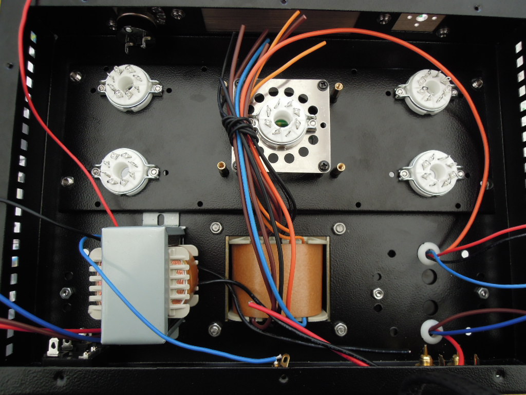
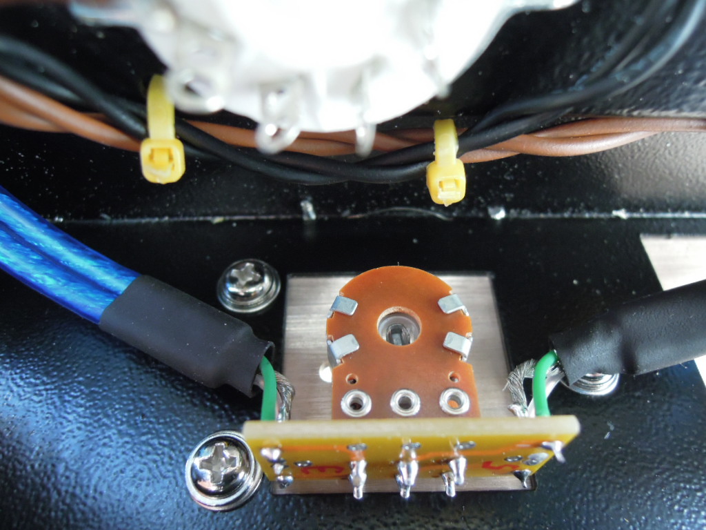
Some clear pictures of the underside of your amp might allow a sharp-eyed viewer to see a problem (though the $%#@ PCB will probably hide some wiring).
Ideas/questions from me:
How did you check the wiring against the schematic diagram and tube pinouts?
If you haven't built a 'dim bulb tester', now might be a good time to do that.
The R301/303 resistors are in the power supply RC stages?
You had all the tubes installed when you first powered up?
The line fuse didn't blow?
You have junk speakers for testing? (A couple of hefty 5-8-10 ohm resistors make a good test load, and are quiet.)
Hi thanks for your reply, I've spent this afternoon re-checking the wiring and found a couple of other resistors that needed re-wiring but my biggest mistake was inserting the 5Z3PJ incorrectly in its holder! Once this was in properly and switched on, no cooking resistors although no audio. This was traced to the speaker output PCB where I thought soldering the output transformer wires to this connected to the speaker wiring posts....not so! Once this was re-wired and speakers connected, hey presto, sound, and pretty good at that, little or no mains hum and no distortion. Very impressed with the crispness and good stereo separation. My only criticism is poor bass response but I need to study the mods mentioned in this forum...that's for another day I just want to enjoy it for a while. If it wasn't for the problems and more importantly your solutions my project would still be in its box. A big thanks to you guys. Wilkij in GB.
Once this was re-wired and speakers connected, hey presto, sound, and pretty good at that, little or no mains hum and no distortion. Very impressed with the crispness and good stereo separation.


Correct, it is a grid stopper: it prevents intrinsic oscillations and radio frequencies to enter in your amplifier.
You can put the stock 10K, but I recently decreased to 3,3K because it also cuts (roll-off) audio hights due to the Miller capacitance effect (that is doubled in paralleled triodes) and could add noise.
You can test different values from 68K to 1K and hear tonal differences (benefits going from smooth sound to a better resolution).
Better to not omit at all also because you (as myself) miss grid stoppers in the El34 circuits
I have also cut the grid resistor from 470K to 150K, for the same problem (high Miller effect capacitance in parallelled triodes). Try also this (try 150K 220K or 330K) because it totally changed in favour my 3D-scene (more focused) and produces much less distortion. I would stay in your case at 150K.
Check all my changes which i will post soon.
Last edited:
You can test different values from 68K to 1K and hear tonal differences (benefits going from smooth sound to a better resolution). Better to not omit at all also because you (as myself) miss grid stoppers in the El34 circuits <snip>
How are you measuring the changes in frequency response and distortion?
Correct, it is a grid stopper: it prevents intrinsic oscillations and radio frequencies to enter in your amplifier.<snip>
Guys,
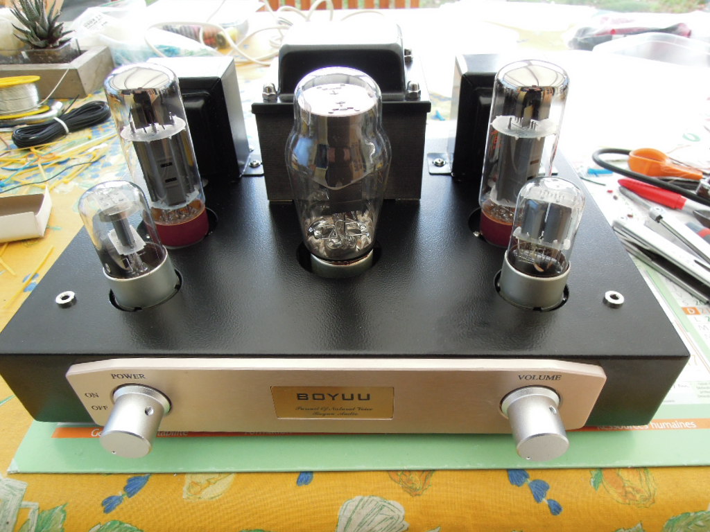
Just stumbled over the thread and as I finished the A9 kit from doukmall on EBay I wanted to share my experiences.
First it was a nightmare to get these doukmall people to provide me even with a schematic. Once that was in, I had to check all the little inaccuracies of the schematics. Largely though, the build is pretty straight forward and the case was neatly built as well. Exceptions and to be dumped before assembly were: rotary switch, pot and sockets. They were absolute cheap crap and relation to the main switch really dangerous. Have kept the original Shuagang tubes for the time being.
Thanks for the tip with the grid resistor, wouldn't have picked that myself, not being a tube expert. Can someone please tell me why the resistor does not attenuate the input signal?
When I insert a 3k res in series, the amp turns significantly quieter, and I don't refer to noise but output level.
All in all with base config, the amp is pretty noisy with hum in the lower and high pot settings and hissing in the middle volume setting. Will try alternative tubes later on, but wanted to check the original first.
The highs are a bit removed and the bass lacks punch, although relatively accurate, just no pressure. Will see how that improves after nicely breaking the tubes in.
I confess I compare that with a recently built SKA amp, which is Mosfet powered, but you have to start somewhere and that is my first tube power amp build.
Cheers!

Newbie at work
Guys,
I reported earlier that I had some issues with noise and had trouble really digesting the provided information by the seller on eBay for this amp kit.
So went back to basic and built the amp as it was shown on the schematics and photos I could find. The only thing I changed was the pot I replaced with a decent ALPS and the rotary mains switch from Lorlin. Further I replaced the flimsy tube sockets with a bit more solid ones.
I ended up with still a bit of noise as in hum, which changed tone with increasing volume, but not really level. Since I had another capacitor (150uF) lying around I paralleled this with the filter cap after the choke, and see the noise reduced markedly. Still some there but not much.
My remaining question would be:
How can the seller offer the amp with a nominal 13W output power per channel (which I couldn't measure) and I can easily turn the pot fully up without even exceeding normal moderate listening level.
Even with my not really super-efficient speakers (tried three different types) I would have expected a little more than that.
Is the amp really expected to be used as an integrated amp without further pre-amplification? Anywhere near clipping I would expect at three to four times the volume output.
Any ideas, other than tube swapping (which I will try anyway for the fun of it)?
It is like new L.E.D Tv's only 2 manufacturers that made the screens but it is the processes in side that makes a excellent L.E.D Tv!!! So you know what I mean about these amps it is the "cheap" design processes that makes it a disappointing amplifier!! I learnt a long time ago if I brought these cheap amps from China I would have to mod them to a point that it changed them significantly So I download the schematics from google and have not looked back to having great sound from the same valves and transformers that came with the original kits. I'm building a 12ax7/6sp3 amp now which is a replacement for the 6N9P as I fine them to be way to high in treble and lacks bass.
Hello everyone, I also recently completed the build of this amp. Initially it had a lot of hum but I managed to get rid of it entirely by including a rectifier bridge with a 2400uf 16v capacitor for the small tube heaters and grounding the minus from the rectifier bridge. The problem that I have is very high voltage, over 700v after the rectifier tube. The output transformer delivered 2X340 volt instead of the specified 315 volts. Can someone tell me the results of their voltages checks.
Hi 6p3c,
Did you measure the voltage in idling or under load, i.e. with the circuit connected? Sounds a bit like the wrong transformer voltage. If you work with 240V mains but the transformer is set for 220V, then 343V would be the consequence. In this case a step down transformer surely is cheaper than a new power transformer.
So you heat the preamp tubes (6n9p) with DC? What is the voltage if you rectify the filament voltage of 6.3V or whatever you transformer produces? I still have some hum in mine, which gets far worse if I swap the Chinese tubes with Russian NOS. DC heating may be a way forward....
Cheers!
Hello happy dyers !
Could somebody send me a circuit diagram for this amplifier ? I received mine without any diagram ... Hopefully, there is internet ...
I have finished the wiring and it works, but i have a buzz. How (and where) do you connect the ground of the chassis from the printed circuit board ?
And i wish to replace the on/off switch to something more secure : do you have a rotating switch to purpose ?
PS : sorry for bad english, but school is so far ...
Gidu
Last edited:
Hi !
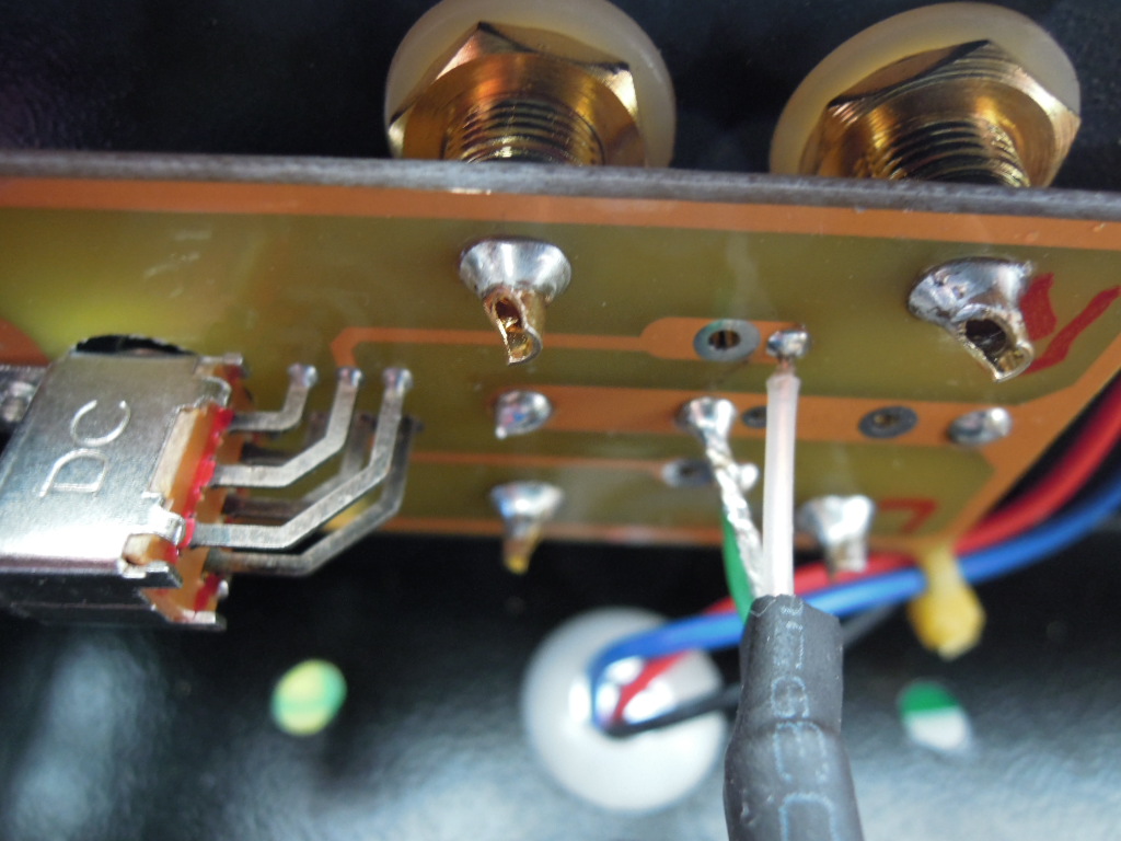
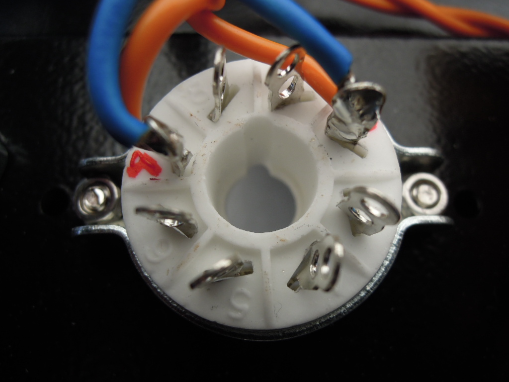
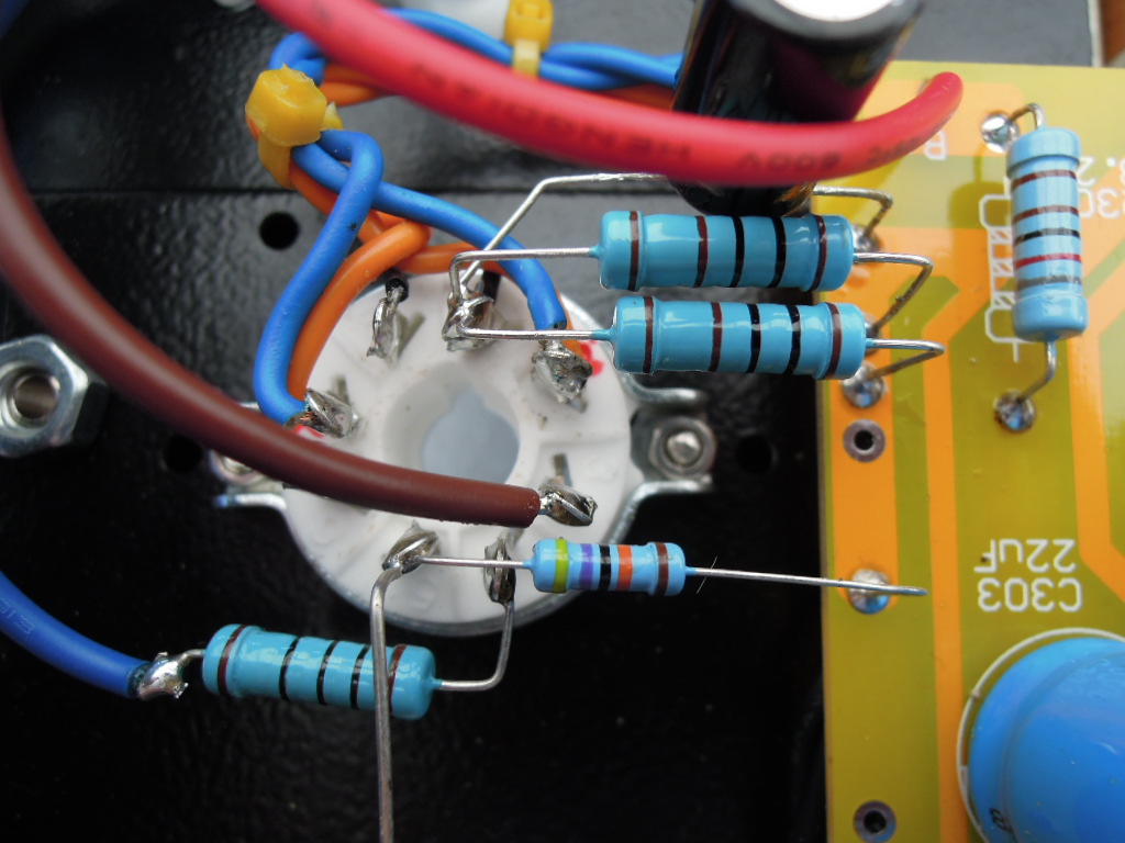
Be carefull, on the first picture, the two output transformers are upside down ! (primary and secondary are inverted ...)
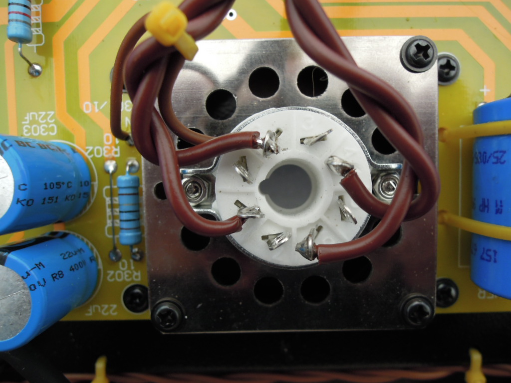
And on the second and third pictures, the cathode connection is on a wrong pin : it must be on the pin number 8 of the socket of the 5Z3PJ valve !
Gidu
Be carefull, on the first picture, the two output transformers are upside down ! (primary and secondary are inverted ...)
And on the second and third pictures, the cathode connection is on a wrong pin : it must be on the pin number 8 of the socket of the 5Z3PJ valve !
Gidu
Last edited:
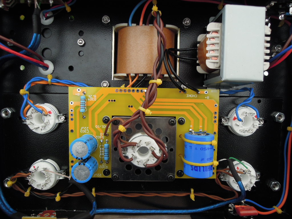
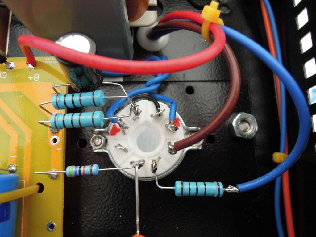
Picture 3:
R301-303, did you replace the three resistors in series with one bigger one? The schematics are a bit dodgy, but I understood from the Boyuu pictures that two are soldered to the PCB and one connects directly to pin 8 of the rectifier valve, which makes three in series.
Maybe that would increase voltage before the choke.
How did you mount the choke to the chassis, I piggybacked them under one output transformer.
- Home
- Amplifiers
- Tubes / Valves
- Boyuu EL34 A9 Tube Amp