VictoriaGuy,
If the voltage is 2.6V, and the [shared] cathode resistor is 2k Ohms, the Total current is 1.3mA.
But there is no guarantee that 1/2 of that 1.3mA is in each triode.
It could be 0.65 & 0.65mA, or 0.45 and 0.85mA, or . . . etc. That is the point of using separate individual 4k Ohm resistors for each cathode. That will help to better auto-balance the currents if both triodes are not identical. And if they are badly balanced currents, you can measure the two cathode voltages and see the imbalance; now you can decide if you want to try another tube to get a better current balance.
Last edited:
Thanks, 6A3.
I guess that Glass Audio article on paralleling tube sections isn't public domain (aka 'free') ? I had a quick look but found nothing.
I understand the theory about detecting imbalance between the tube halves, but I don't understand the idea of 'auto balancing'.
Could it be done as easily with separated plate resistors?
Also, does it make any practical difference if the currents are slightly different in each tube 'half' in a circuit like this where the grids and plates are tied together?
Whenever I test dual triodes (in a tube tester) there's usually a couple of percent difference between the two halves of the tube.
Lots to learn, obviously.
VictoriaGuy,
If the voltage is 2.6V, and the [shared] cathode resistor is 2k Ohms, the Total current is 1.3mA.
But there is no guarantee that 1/2 of that 1.3mA is in each triode.
That current seemed low to me, looking at the tube curves.
What do you think?
It looks like the tube specs are showing 2ma or so for each half of the tube.
(I understand that the current changes with the signal voltage on the grids.)
This was what I measured a while back. Post 648
6N9P PIN 2 OR 5 ANODE 193VDC(left tube) 201 (right tube)
pin 3or6 CATHODE 2.6VDC
Thanks.
")
That current seemed low to me, looking at the tube curves.
Yup, a bit low. That's like around 1/4watt plate dissipation per section, looking into a 75k load.
jeff
"Glass Audio" magazine was published by Ed T. Dell. In 2001, it combined with "Speaker Builder" and "Audio Electronics" and became "Audio Xpress" magazine. I do not believe that the article was ever released for re-publication or copying.
The candidates were 6SN7, 20 NOS, and 10 used tubes (all 60 triodes tested good in a tube tester) and were tested in the article: "Paralleling Tubes Effects". The data collected was 600 measurements, including DC current, AC gain, and distortion out to the 7th Harmonic. Each dual triode pair was tested against itself, and against each of the triodes in a second dual triode pair, until all 60 triodes were tested alone, and tested paralleled with 3 other triodes (one at a time). They had 1 k Ohm in each cathode with individual bypass capacitors, and 25k Ohm in each plate. The grids were connected together. Each triode current ranged from 7.4 to 8.3mA of current, when they all had their own cathode resistor, and their own plate resistor.
When the cathodes were connected together and the plates were connected together, the total self bias resistor was 500 Ohms, and the total plate resistor was 12.5k Ohms. Even though all the individual un-paralleled triode current maximum variation was 12%, when the cathodes and plates were paralleled, sometimes one triode would take over, the result was one triode had up to 2 times as much current as the other triode in the paralleled set. That is a mismatch of 50%.
So from 12% to 50% mismatch . . . that indicates that a mismatch of say 2% for individual triodes may result in a 8% mismatch when they are paralleled (unless you use individual self bias resistors and individual bypass caps . . . and do not parallel the cathodes, just parallel the plates and grids). As long as the tube currents were reasonably matched during parallel operation, the -dBc of each harmonic number (2 - 7) were merely the simple average of the two individual un-paralleled sections.
Last edited:
What chart are you using? I'm having a hard time understanding.
That current seemed low to me, looking at the tube curves.
What do you think?
It looks like the tube specs are showing 2ma or so for each half of the tube.
(I understand that the current changes with the signal voltage on the grids.)
I have a hard time understanding, too..
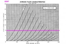
In the work that 6A3 describes, they were running the triodes in the 6SN7 at about 8mA (each).
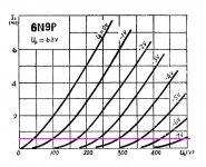
In the Boyuu, it seems that each triode in the 6N9P is running at about 0.65 mA (assuming the current is divided equally between the two halves of the tube).
Looking at the 'Plate characteristics' graphs (Current vs voltage for different grid bias voltages), the working currents seem to be in different parts of the graph.
In the work that 6A3 describes, they were running the triodes in the 6SN7 at about 8mA (each).
In the Boyuu, it seems that each triode in the 6N9P is running at about 0.65 mA (assuming the current is divided equally between the two halves of the tube).
Looking at the 'Plate characteristics' graphs (Current vs voltage for different grid bias voltages), the working currents seem to be in different parts of the graph.
Attachments
They had 1 k Ohm in each cathode with individual bypass capacitors, and 25k Ohm in each plate. The grids were connected together. Each triode current ranged from 7.4 to 8.3mA of current, when they all had their own cathode resistor, and their own plate resistor.
When the cathodes were connected together and the plates were connected together, the total self bias resistor was 500 Ohms, and the total plate resistor was 12.5k Ohms.
Thanks, 6A3.
I found another thread here where you describe those results in more detail.
Those tube conditions were in a working amp?
You said you did 'listening tests' with paralleled elements, with relay switching. It must have been quite complicated?
BTW, for readers here, 6A3 found that nobody could hear differences between parallel and non-paralleled tube sections - that's how I read his statement, but I may be wrong.
Will half a 6N9P not have enough gain to drive the EL34 in SE?
How about the 0.65ma how do you come to this value based on the 2.6volts?
I have a hard time understanding, too..
In the work that 6A3 describes, they were running the triodes in the 6SN7 at about 8mA (each).
In the Boyuu, it seems that each triode in the 6N9P is running at about 0.65 mA (assuming the current is divided equally between the two halves of the tube).
Looking at the 'Plate characteristics' graphs (Current vs voltage for different grid bias voltages), the working currents seem to be in different parts of the graph.
Ohms Law
V=IR
2.6 V voltage drop across a 2k ohm resistor
I= 2.6/2000
I=0.0013 A or 1.3 mA
That's the current for both 'sides' of the tube, since all the tube current flows through that one cathode resistor.
So, if the current is shared equally between the two triodes, it's 1.3/2 mA or 0.65mA for each triode.
I think that's correct?
It doesn't seem to be an issue at all; the data and scope traces that Frank posted seemed to indicate the A9 is working OK as designed.
I only mentioned it because I don't really understand the choices that were made in the A9 amp design. When I bought a similar amp kit some years ago, a different circuit (using many of the the same components) was suggested to me by participants here at diyaudio, and I just built it without a lot of questions about the choices that were made.
BTW, Merlin Blencowe's book "Designing High Fidelity Tube Preamps" has a good chapter on tube curves and how to interpret them. The book was a Christmas present, so I'm just starting to work my way through it.
Last edited:
I'd would like to try this mod on the preamp socket/tube So i would remove the connection between pin 3 and 6 (cathode). I would then replace the 2k resistor from pin 3 and 6 with two 4k resistors. One from pin 3 and one from pin 6 as shown in VictoriaGuys sketch.
Also I have 3.3k resistor on pin 1. Should i keep this and add an additional 1k resistor on pin 1 and another on pin 4?
Also I have 3.3k resistor on pin 1. Should i keep this and add an additional 1k resistor on pin 1 and another on pin 4?
Attachments
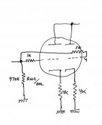
Yes. The other ends of the 4k resistors go to the circuit ground point (where the 2k resistor was connected).I'd would like to try this mod on the preamp socket/tube So i would remove the connection between pin 3 and 6 (cathode). I would then replace the 2k resistor from pin 3 and 6 with two 4k resistors. One from pin 3 and one from pin 6 as shown in VictoriaGuys sketch.
That 3k3 resistor is a grid stopper, I think. So you don't need both the 3k3 and a 1k. The important thing is that the grid stoppers connect right to the tube socket (close), and the 470k is not connected to the tube socket - as pointed out by 6A3, all the connections to the grid have to 'go through the stopper'. So you may have to find a new spot to join the two grid stoppers, the 470k resistor, and the volume control wiper. If the volume control is close enough, you could use it for the connection point.Also I have 3.3k resistor on pin 1. Should i keep this and add an additional 1k resistor on pin 1 and another on pin 4?
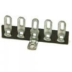
It's not a good idea to make joints 'in mid air' but it seems to be done fairly often, so that could be a last resort. You may have a spot nearby to connect a solder lug strip with a couple of (non grounded) connection points.
Attachments
Right now I have the 470k resistor and the 3k3 resistor going
To the same pin either 1 or 4. I'll take a picture tomorrow.
Yes, that's what the schematic for the A9 shows.
If you want to, you can use two grid stopper resistors, 1k Ohms each, one on pin 1, and one on pin 4, then tie the other ends of the grid stopper resistors to the volume control wiper that is also connected to the 470k Ohm grid resistor.
The key purpose of having a grid stopper resistor is to isolate the control grid from stray wiring capacitance and wiring inductance. That is why all of the circuit that needs to connect to the control grid has to pass 'through' the grid stopper resistor. It is the only part that connects directly to the control grid. I use 1k Ohm grid stopper resistors on control grids.

To which post are you referring?Please do NOT quote the entire post above yours when replying.
Mine, with the 2-line quote from Gregas?
It is difficult to tell, as you did not quote any part of my post.
There are several conversations going on simultaneously here:
6A3 on the parallel triodes
Fdlima on amp measurements
and also Gregas on possible mods.
Sometimes it is confusing without quotes.
- Home
- Amplifiers
- Tubes / Valves
- Boyuu EL34 A9 Tube Amp