Hi chaps. Apart from soldering my fingers a few times I'm progressing! I can't make out from the diagram or the photos what the correct pins are to connect the power supply to for both the EL34 and 6N9PJ valves. I think the EL34 may be 2 and 7 but can someone tell me what the pins are for both vales please?
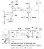
Hi chaps. Apart from soldering my fingers a few times I'm progressing! I can't make out from the diagram or the photos what the correct pins are to connect the power supply to for both the EL34 and 6N9PJ valves. I think the EL34 may be 2 and 7 but can someone tell me what the pins are for both valves please?
By 'power supply', you mean the heater/filament supply?
Even with a good schematic, I usually have copies of the tube data sheet (first page) for each tube with me when I'm working...useful for that double and triple-checking.....
")
You can find those online by searching on 'tube data' for each tube...
I also print extra copies of the schematic and use a highlighter marker to remind me which connections I've made. Everybody will have their own methods of avoiding nasty fireworks.....
By 'power supply', you mean the heater/filament supply?
You can find those online by searching on 'tube data' for each tube...
Remember tube datasheet pin out are always from "bottom view", not from the top! and numbering should be clockwise.
Post a detailed photo hand by hand where you are with the kit: it is better we get a look before you switch the power on.
Looking at the schematic (and knowing how output transformers are wound), I'd measure the resistance from the black wire to the other two output leads. There will be a higher resistance across the whole secondary (0 black wire-8 ohm lead) than from the black wire to the 4 ohm tap.
BTW, I always double-check the transformer leads by measuring continuity (resistance) to make sure I'm working with the correct connections. I wouldn't trust a photo or diagram completely, since checking is only a matter of a minute.
BTW, I always double-check the transformer leads by measuring continuity (resistance) to make sure I'm working with the correct connections. I wouldn't trust a photo or diagram completely, since checking is only a matter of a minute.
Looking at the schematic (and knowing how output transformers are wound), I'd measure the resistance from the black wire to the other two output leads. There will be a higher resistance across the whole secondary (0 black wire-8 ohm lead) than from the black wire to the 4 ohm tap.
BTW, I always double-check the transformer leads by measuring continuity (resistance) to make sure I'm working with the correct connections. I wouldn't trust a photo or diagram completely, since checking is only a matter of a minute.
Mine should be similar to yours.
http://www.diyaudio.com/forums/tube...tube-amplifier-5z4p-rectifier-review-mod.html
You should measure like about 1.1 ohm (or about 19 mH) ground to the 8 ohm and 0,8 ohm (or 11,3 mH) ground to 4 ohm. Measurements are not doubling linear but follow exponential rules. Since the resistance are very low, if you have difficulty just put across the primary a 12-24 AC voltage via an extra small transformer and measure the mV AC voltage across the output: the hightest voltage one is for the 8 ohm tap.
In this case you can also determine which will be the primary load. Voltage should be in the ratio of 1:20 for the 8 ohm tap, so resistance in the ratio of 1:400 so (8ohm * 400) you will get 3200 ohm of primary tube load.
OR, in the ratio of 1:28 for the 4 ohm tap so resistance in the ratio of 1:800 so (4 ohm * 800) to get the same 3200 ohm of primary tube load.
If you put 12 VAC at the input of the output transformer you should get 0,6 VAC for the 8 ohm tap and 0,45 VAC for the 4 ohm tap, or values similar to these.
If you put 24 VAC across the input of the output transformer you should get 1,2 VAC for the 8 ohm tap and 0,9 VAC for the 4 ohm tap, or values similar to these. The output taps must be open, without any load, during these measurements.
It would be useful if there was some documentation to go with these Chinese transformers. My colours are black, red and blue!
On your schematic look at where B+ connects to the OPT and the other side is the ohms tap, it should be safe to say the other side corresponding with B+ would be 0 ohm ground the next would be 4ohm and the top would be 8ohms.
Attachments
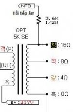
Ok people. It powers up and the valves glow and nothing has caught fire or blown up so I'm assuming that must be good. The last thing I have to do now is to connect the three output wires to wherever they need to go. I'm still stuck on how to work those out. The output wires are red, blue and black. On the other side of the transformer the B+ wire is red. I'm going to go with black to earth I think....
I need a bit of help now. All built up and it hasn't blown up. When I power up with speaker and a source connected there is a horrendous buzzing noise as the valves warm up - like deep feedback. But when I switch the amp off and as the valves cool the source plays through the speakers. I must be close. What should I check first?
The last thing I have to do now is to connect the three output wires to wherever they need to go. I'm still stuck on how to work those out. The output wires are red, blue and black. On the other side of the transformer the B+ wire is red. I'm going to go with black to earth I think....
It's safer (and can be a lot cheaper) to check all your connections against the schematic before powering up.
Unless you have a good idea of what will happen, it's also better to get 'everything' connected up before applying power, IMO. This includes dummy load or speakers.
Also, checking the output transformer windings with an ohmmeter and sorting out the leads is a good idea - labelling the leads or making clear notes in your 'project notebook' would be my recommendation. BTW, it's not common, but I'm pretty sure I've seen transformers where the side where the wires emerged wasn't a surefire clue to their function.
Can you upload some pictures and the schematic you are following?
- Home
- Amplifiers
- Tubes / Valves
- Boyuu EL34 A9 Tube Amp