R1ch, your schematic is the same as the one I built. As far as the sound quality goes, I replaced my Chinese driver tubes with a pair of NOS Sylvania 6sl7GT's with great results. Most of my experimenting with my amp was with components other than tubes. I've replaced the caps with better quality ones, some of the resistors were replaced as well. The resistors did not make much difference. Higher grade coupling caps make a more significant difference. Also I played around with the cathode bypass caps and found that you can alter the quality and output of the amp by changing the caps.
Have fun experimenting.
Carlo
Have fun experimenting.
Carlo
hi dear All,
because this kit is available for 199e incl. the shipping in Germany, Iam asking if it is suitable for a triode modification, 6BG4 triode with octal socket and 6,3V/1A heating.
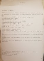
And, I think there is enough iron in it , because of 12kg weight.
But, according the schematic, it has only 2 separate 6,3V voltages, this means, that the
pre tubes must be heated together with one 6BG4. Has anyone tried this out, before I order the kit? thanks and best regards, Armin
because this kit is available for 199e incl. the shipping in Germany, Iam asking if it is suitable for a triode modification, 6BG4 triode with octal socket and 6,3V/1A heating.
And, I think there is enough iron in it , because of 12kg weight.
But, according the schematic, it has only 2 separate 6,3V voltages, this means, that the
pre tubes must be heated together with one 6BG4. Has anyone tried this out, before I order the kit? thanks and best regards, Armin
Last edited:
Use of 6BG4
The transformer spec shows a total of 2.0A for the input tube 6.3V winding. Using the Chinese 6N9s provides all the gain necessary to drive the EL34 output tubes. A possible upgrade that others have suggested is to replace the 6N9s with 6SL7s. Its also advisable to add cathode bypass capacitors to the input tubes (across R104/204) to get much better high frequency response.
I am still using the 6N9s with jj KT77s with acceptable results. I use this amplifier as my primary sound system amplifier and like the performance. Its a great buy!
tubesaurus,
Did you really mean 6BG4?
Is it a Directly Heated Triode?
If you meant 6BG4, what are the tube ratings?
Or did you mean 6B4G, an Octal indirectly heated triode?
The 6B4G is rated for maximum 325V, and 15W. At 325V, that would be 46mA.
Or for better performance, you should use it at 300V and 50mA, or 250V and 60mA.
But the Boyuu kit has B+ that is much higher than 325V across the EL34, even if you subtract the self bias voltage from the B+ voltage.
The B+ minus the self bias voltage will be too much for the 6B4G, so you will have to find a
good way to reduce the B+ voltage.
You might remove the capacitor that is immediately after the tube rectifier (and that is at the input of the choke), and put that capacitor at the output of the choke.
If the 3 Henry choke has enough inductance, and enough load current, that will reduce the B+ by a lot. There might be too much hum this way, because the B+ was not designed to be a choke input supply. In that case you will need the choke, then first capacitor to ground, then a new series resistor, than 2nd capacitor to ground. That will be the B+ to the output tubes.
The rest of the resistors in the original power supply will have to have reduced resistance in order to give high enough B+ to the other stages.
I would attempt this for the B+, but then I have quite a bit experience in designing and tailoring power supplies.
For directly heated triodes on the Boyuu amp, you will need at least one more 6.3V transformer.
The tubes need to have their own individual self bias network, so that can not be powered off the single EL34 filament winding. Where will you fit the transformer? You will also need to provide a center tap to each 6B4G filament winding, or a pair of 25 Ohm resistors to simulate the center tap, and the bias network goes from there to the “center tap”. Without the ‘center tap’, the hum will be unbearable.
The 6B4G will probably need a higher bias voltage than the EL34.
That means the self bias resistor will have to be changed to a larger resistance, and perhaps higher power rating, and the bias bypass capacitor will probably have to be changed to a higher voltage rating.
Whatever driver tube you use, it will have to have enough gain to linearly swing a total of 2 times the 6B4G bias voltage. Otherwise you will not get the full power out of the 6B4G.
And the full power of the 6B4G is about 3.5W, that is less than the EL34.
But I do like the idea of you using 6B4G tubes.
You can put bypass capacitors across the input tubes self bias resistors, R104 and R204 (that will increase the gain, and will make it easier for the driver to drive the 6B4G)
You will Not need to use negative feedback (as per some of the schematics on this thread which Do use negative feedback).
Either way, with care, you should get good sound from EL34/KT77 versions, or 6B4G version.
Greetings,
I've been reading and studying this thread for a couple of months now. I received my own BOYUU amp about a month and a half ago. I bought a fully assembled one, as a recent stroke damaged my eyesight and everything is blurry. I can handle a few mods, but no way do I want to assemble a kit, although I certainly have the skill and past experience to do so.
Mine worked pretty good right from the beginning with the exception of a bit too much hum. I added a couple of resistors to ground on the 6SL7 heater transformer wires and cut it down to acceptable levels. I also tried converting to triode mode, which helped tighten up the bass a bit, but ended up putting back in UL for the extra headroom.
I using a pair of Harrison Lab 100 Hz high-pass filters on the inputs to keep the amp from wasting power in an area it doesn't handle well, anyway, and am using a plate amp to drive bass augmenters. This works very well. The bass augmenters are Hawthorne Audio 15" Augies on small open baffles in the corners. The mains are Caintuck Audio Betsy open baffles with 92.5 dB sensitivity specks. Working nice so far. Someday I plan to build bigger OB's using a pair of vintage EV LS12 drivers in parallel on each baffle, which should give me 98 dB speakers per channel. I look forward to this.
Now, question time. The amp shows some high frequency roll-off that wasn't there using my old TAD-60 PP amp on the same speakers. I read a few pages back were someone commented about Miller effeck from the two halves of the 6SL7 tubes being run parallel. Could someone clarify this for me, and what can I do to make it better?
BTW. I have a tube line preamp, so gain at the amp isn't a big issue.
Dave
There are many circuits proposed in the 25 pages of threads here.
Miller effect can cause high frequency roll off, unless the grids are driven by a medium to low impedance (that is your preamp). Also included are the parts leading to the grids of the parallel 6SL7.
If you use a 6SL7 in parallel, and you have a preamp with a volume control to drive it:
Use a preamp that has a medium or low impedance output.
Use a very short shielded cable from the preamp to the input connector.
Use a 470k Ohm resistor from the input jack to ground (and eliminate the 100k pot)
Use a 1k Ohm grid stopper resistor from the input connector to the parallel grids.
Do not use the 10K Ohm grid stopper, as proposed in one of the threads. 6SL7 has a grid to plate capacitance of about 3pF (6pF for 2 triodes). The u (mu) is 70. Miller effect can be up to 70 x 6pF = 420pF
The - 3dB point of 10k Ohms and 420pF is 38kHz, and the -1 dB point is 19kHz. 10k seems a little to large, because other parts of the amp also have high frequency roll off, like the output transformer. -1dB here, -1dB there, -1dB another place, and pretty soon you are talking about -3dB (half power).
Last edited:
My preamp is one of those little Chinese preamps on ePay that uses a couple of J61 tubes. I assume it has a rather high output impedance.
For the price, I had to try it. Sounds very clean.
http://www.ebay.com/itm/Mini-6J1-Au...903483?hash=item43fdcd5e3b:g:XmUAAOSwOgdYxrF5
Dave
For the price, I had to try it. Sounds very clean.
http://www.ebay.com/itm/Mini-6J1-Au...903483?hash=item43fdcd5e3b:g:XmUAAOSwOgdYxrF5
Dave
Last edited:
I have had my Boyuu amp for nearly a year now. It's the A10 version using 6N2P and it was ready-built. I changed these to 6N2P-EV and have had no problems at all.
I'm going to try a few tube swaps and so have ordered a pair of 'big bottle' 6CA7 to replace the EL34-B. Is this a straight drop-in replacement or do I need to change any other components? I have read that the 6CA7 has more headroom so would it benefit me to change the Chinese rectifier valve with a GZ34 for lower voltage drop?
My speakers are Mission 720, which I refurbished several months ago having has them from new in 1979.
The 6CA7, a beam power tetrode, and the EL34, a power pentode, are electrically "equivalent". Various specimens of both types bias differently and, in amp with "fixed" bias, that fact requires careful attention. OTOH, in an amp with self bias, like a Boyuu, insert the tubes and see what happens. Reworking the self bias network is unlikely to be necessary.
Chinese (Russian too) ST bottle 5U4 "equivalents" are garbage. Replacing the junk with either an OS GE 5U4GB or a current production EH 5U4GB is (IMO) appropriate.
Chinese (Russian too) ST bottle 5U4 "equivalents" are garbage. Replacing the junk with either an OS GE 5U4GB or a current production EH 5U4GB is (IMO) appropriate.
In my PP TAD-60, I tried several tubes, including various EL34's, 6CA& and KT77. The JJ KT77 was the best all around tube for that amp. Once I get the BOYUU running just the way I want, I'll try the KT77 next. Old stock any of those tubes is out of my budget for now.
Dave
Dave
The 6CA7, a beam power tetrode, and the EL34, a power pentode, are electrically "equivalent". <snip>
Svetlana 5U3C are russian and the best of
older triple double rectifier meesa boogie use thems
its very high quality tube spring coils heather
much better than 5V4 and others cheaps 5U4
www.thetubestore.com - Winged "C" (SED) 5U4-G Black Plate Rectifier Tubes
Yet Another A9, but not exactly
Hi guys,
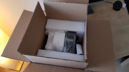
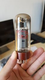
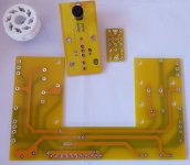
I just received my A9 and because it is a little bit (but essentially) different from what you have discussed up to now, I decided to share some photos and impressions with you.
I bought the unit from ebay.com, it was labeled "EL34 Vacumm Tube Amplifier Single-ended Class A HiFi Stereo Amp DIY KIT 12W+12W" from doukmall. It is advertised as a "2017 design" + lots of nice words about the quality of the materials
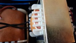
My item was shipped from Germany. It arrived really fast (just a couple of days), but even this doesn't make the $89 shipping sweater for a $195 item
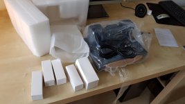
So what you can see on the pictures actually proves that they have improved the package substantially. The packaging is great - two boxes together, it sustained being delivered to me upside-down and who knows what else.
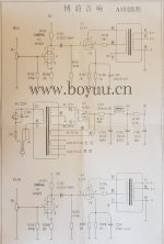
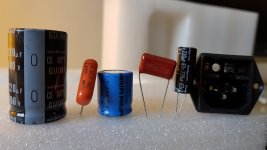
Notice that there is a change in the schematic written with a pen for R103 and R203. There are other differences also, which are not written on the schematic - all caps are high quality ones - from Philips, Nichicon and Rubycon, the big cap is now 220uF. I plan to build the amplifier with the original circuit and after listening to it to improve this and that. Reading this post I was left with the impression that I'll have to recap the unit entirely, so I bought all the caps + the stuff for the "improvements" that I identified at first look on the schematic here before receiving my package. Now I changed my mind and I'll improve things after listening to the original sound
Things will happen in the next month or two and I'll keep track of the progress here.
Hi guys,
I just received my A9 and because it is a little bit (but essentially) different from what you have discussed up to now, I decided to share some photos and impressions with you.
I bought the unit from ebay.com, it was labeled "EL34 Vacumm Tube Amplifier Single-ended Class A HiFi Stereo Amp DIY KIT 12W+12W" from doukmall. It is advertised as a "2017 design" + lots of nice words about the quality of the materials
My item was shipped from Germany. It arrived really fast (just a couple of days), but even this doesn't make the $89 shipping sweater for a $195 item
So what you can see on the pictures actually proves that they have improved the package substantially. The packaging is great - two boxes together, it sustained being delivered to me upside-down and who knows what else.
Notice that there is a change in the schematic written with a pen for R103 and R203. There are other differences also, which are not written on the schematic - all caps are high quality ones - from Philips, Nichicon and Rubycon, the big cap is now 220uF. I plan to build the amplifier with the original circuit and after listening to it to improve this and that. Reading this post I was left with the impression that I'll have to recap the unit entirely, so I bought all the caps + the stuff for the "improvements" that I identified at first look on the schematic here before receiving my package. Now I changed my mind and I'll improve things after listening to the original sound
Things will happen in the next month or two and I'll keep track of the progress here.
Attachments
Last edited:
I dislike a few the parallel triodes like Sishido style but ..."Triodes can be paralleled to increase the signal-to-noise ratio. This is because the noise sources of the two triodes are uncorrelated and add as the square root of the sum of the squares of the individual noise sources, while the signal is correlated and adds directly, giving a 3dB improvement in signal-to-noise ratio. "
An other reason is a half ouput source impedance to drive the EL34 grid.
The Miller efect is twice as simple triode.Roll-off at the high frecuencies.
I prefer the SRPP or better the mu-follower tipology: very low ouput, high gain, high liniality, CCS, easy and cheap to do and excellent PSRR (silent from de DC source)
I use a mu-follower with a 6n2p-ev Kaluga valve.
Fine.
Cheers
Hi hego,
today I found that the local electrical shop has many NOS tubes in their warehouse. I bought 2 russian 6Н9С for $4. Тhey promised they'll check further for 6Н2П, because they actually found the lable on the floor, but not where it belonged to
So, could you please share your prefered schematic for the mu follower and the SRPP with these tubes?
Don´t complicate the things.The 6n2p (6ax7) is the noval versión of the octal 6n9s (6sl7).Must mod the base.You can try first with the octal versión.(6n9s)
For a SRPP exemple see #22 of this thread.
When we work with a srpp, cascode or mu-folower, is important the point B3 of schema. Is the voltage reference between catode/filament.The catode of the up triode is near at the anode of the low one.Avoid short filament/catode about 100V DC max.
An other interesant mod is the use of a courrent sink in the catode of EL34.The cheap LM317 or LM783 IC do the job. You can set easy the disipation of the pentode with a help of a tinny resistor.
1.25V/resistor= catode courrent and this corrent X voltage of the tube = dispation . 25W is the maximal for EL34 and similars.
See this thick in the A10 cousin amplifier at #44 (50mA here) on bottom link
Boyuu hifi Equis A10 EL34B+6N2 SE Tube Amplifier with 5Z4P rectifier: review and mod
Cheers
Thanks!
The different preamp tubes I'm buying only to compare the sound subjectively. There are adapters on ebay for 8 to 9 pin double triodes, so it's not a big deal. Also... the price on which I found them is a bargain
Thanks for reminding me of the filament to cathode voltage. I have that in mind for the mu-follower.
Interestingly - the Shuguang's EL34B has a 30W plate dissipation limit, most probably I'll try to hit that
- Home
- Amplifiers
- Tubes / Valves
- Boyuu EL34 A9 Tube Amp