cman008 - how old is the dimmer switch? If it's a very old one for incandescent lamps (i.e. 'hot wire' like valve heater) it could be very electrically noisy. Really old ones you could hear the buzz from the switch...
Modern dimmer switches for both LED and wire lamps are excellent with no noise, however you have to be selective with make.
Modern dimmer switches for both LED and wire lamps are excellent with no noise, however you have to be selective with make.
Modern dimmer switches for both LED and wire lamps are excellent with no noise, however you have to be selective with make.
That may be true in the UK - not in Canada/USA where those electronic dimmers and the SMPS 'transformers' for halogen lights spew AM interference.
If you have an old 'handheld' transistor radio or AM Walkman, just take a walk around the house...you can follow the in-wall wiring by the RF noise.
Ask any ham radio or SWL guy and you will likely hear the same story.
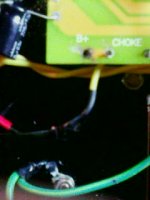
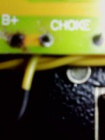
Have you any way of posting a picture of this?
a91gti,
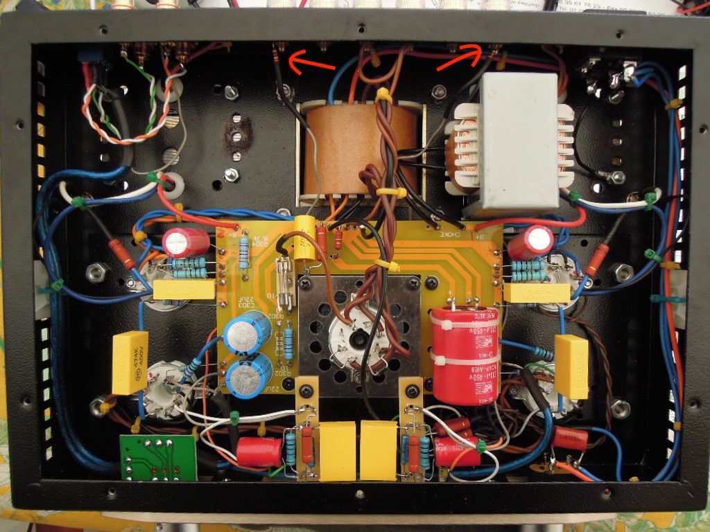
Here are the photos of that burnt B+ connection and the yellow wire is the bypas link as I explained earlier. I wrap all up with insulating tape, because I did'nt have any heat shrink big enough for all three wires. Sorry the camera did'nt show the black wire agaianst the black chassis
 .
.Attachments
Last edited:
Pictures of point-to-point wirings WOULD be very useful
Hi All,
The lack of documentation with the Boyuu A9 was disconcerting at first but soon enough things started to make sense. I have a background in engineering documentation (20 years integrated circuit design in Silicon Valley) so how I made sense of the A9 was to draw everything out before starting construction. It’s the kind of thing that I would find useful so if anyone finds them helpful, great!
dicksonmaxcy@earthlink.net
The schematic shows what I found worked best for me. I considered using a feedback scheme but I found the completed amplifier had a noise level below the threshold of my Tektronix TDS210 oscilloscope anyhow so I didn’t bother with adding complexity. As well I found that the fuse had to be a slow blow type because of all the extra capacitance in the power supply filter chain.
Two other things – I too had trouble soldering so I looked at the label on the solder; lead free! What tha…? So I sent off for some 1.5mm 37/63 Kester solder – problem solved. As I was having to use a very high temperature to solder with the lead free stuff I was melting the plastic insulation of the wires so I shrunk on 2mm of heat shrink at the edge of the insulation.
Best,
Dick
Attachments
Hi 6A3sUMMER,
Yes. You are entirely correct; I had not considered that. But in truth I have never experienced such a fault myself.
Back in the '80s I worked as a designer/manufacturing engineer for mass produced industrial products. For the many years that I worked in this capacity we never experienced shorting in the windings, either in product test or incoming inspection. Of course, this could still happen.
I will look at the measured levels of noise conducted interference in my A9 amplifier and if I see none I will ground one end of the secondary for safety considerations. Thanks for your input.
Best,
Dick
P.S. Before I worked as a designer I worked as a roady for rock bands back in the '70s. Those were the days and yes, we often had amplifiers on fire although I never observed shorted windings in the charred remains. Sadly, the 3AG fuses used in Fenders and Marshalls at the time would fail to blow properly quite regularly.
dmaxcy,
Since your transformers are single ended, it might be nice to measure the capacitance from the primary windings to the secondary windings.
A very large high frequency note might cause quite a bit of capacitive current to the secondary.
Or, instead doing a capacitance measurement, you could apply a high frequency signal from a test generator, and with the secondary loaded (8 Ohm), measure the signal of the floating secondary to ground.
A totally separate short mode:
Once I had a brand new out of the box shorted transformer.
I had not even mounted it on the new amp.
The Primary was shorted to the Laminations.
That could have been a killer if I had done a breadboard amp!
Since your transformers are single ended, it might
Finished for now?
Hi all, just completed some mods and tested the amp. Completely quiet. Not even a whisper. Sounds awesome in both modes but I prefer the triode mode. Still waiting on a better pot (the one I bought will not fir this tiny chassis) Also I have to upgrade the input section (pulling that dang PCB will be a pain) Overall very pleased with the sound. I'm just going to enjoy it for a while before I pop it open. Now I move on to my new project. I'm going to make a lower powered amp with 6EM7 tubes. I read an article about an accordion amp (not literally the instrument lol) that is based on the 6EM7 tube. I'll keep you guys posted.
Here's a link:
http://www.diyaudio.com/forums/tubes-valves/120835-first-build-6em7-works-2.html
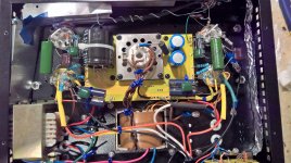
BTW here's a pic of the final product. Not my prettiest work but dang it sounds good!
Hi all, just completed some mods and tested the amp. Completely quiet. Not even a whisper. Sounds awesome in both modes but I prefer the triode mode. Still waiting on a better pot (the one I bought will not fir this tiny chassis) Also I have to upgrade the input section (pulling that dang PCB will be a pain) Overall very pleased with the sound. I'm just going to enjoy it for a while before I pop it open. Now I move on to my new project. I'm going to make a lower powered amp with 6EM7 tubes. I read an article about an accordion amp (not literally the instrument lol) that is based on the 6EM7 tube. I'll keep you guys posted.
Here's a link:
http://www.diyaudio.com/forums/tubes-valves/120835-first-build-6em7-works-2.html
BTW here's a pic of the final product. Not my prettiest work but dang it sounds good!
Attachments
Last edited:
This amp will never be finished ...
Last modification: I have integrated a feedback with the possibility of switching ON / OFF.
Here are some pictures of the surgery :
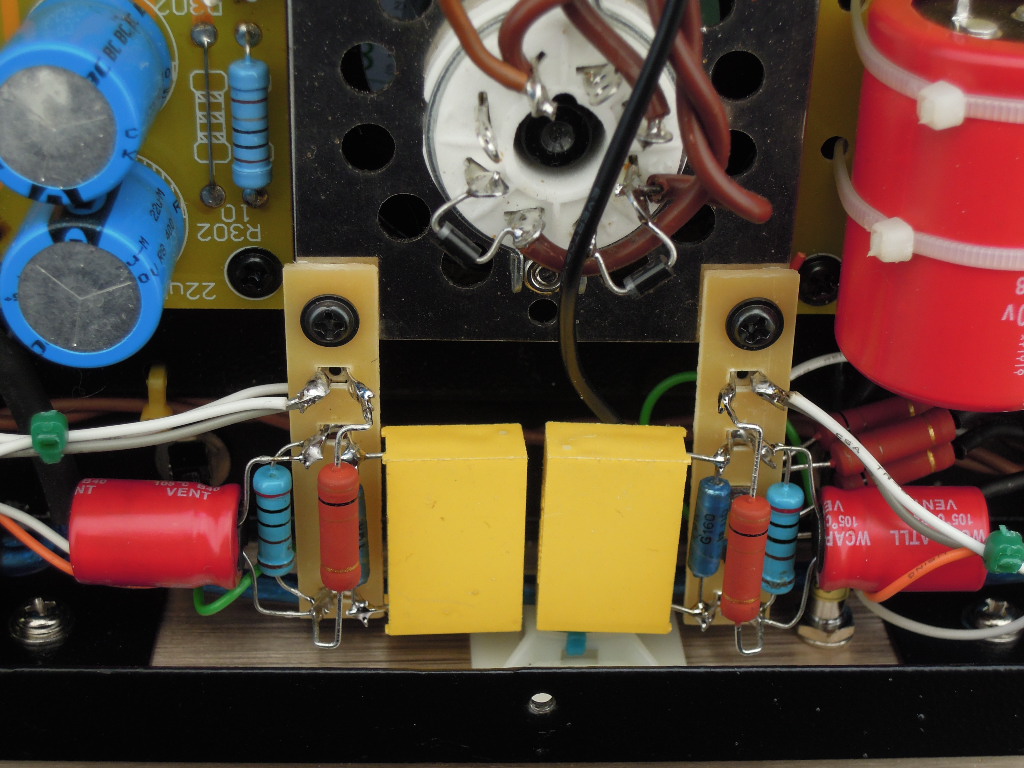
New appearance of the chassis with the modification
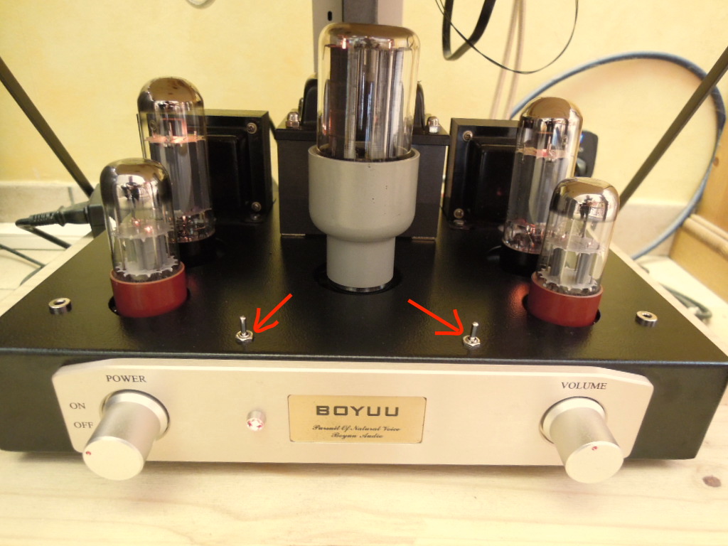
The two switches ON / OFF (1 per channel) of the feedback
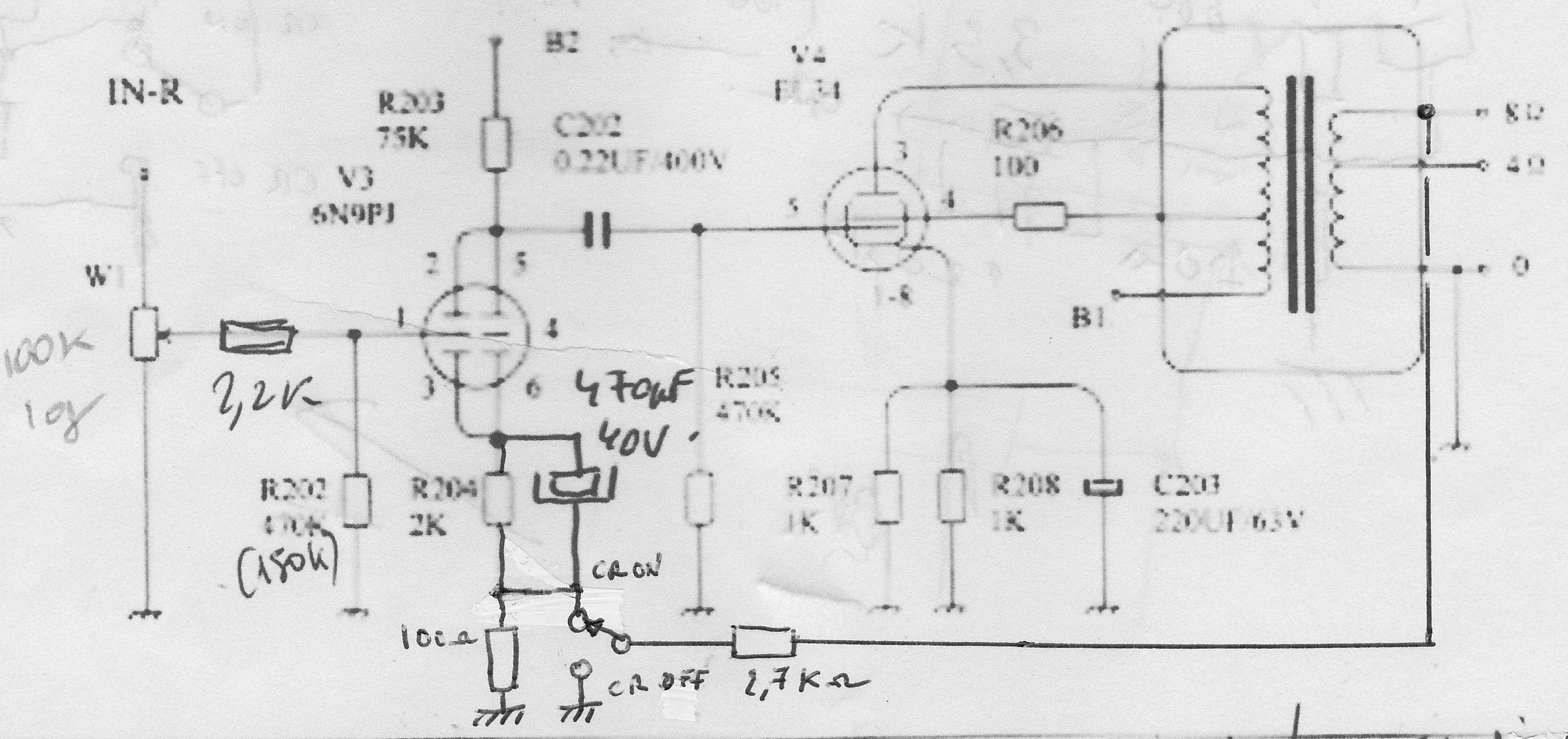
Diagram (partial) of the Boyuu A9 with the feedback
I have used a number of similar schemes to incorporate this mod, so I do not know exactly the rate of feedback, but I think it's still relatively low, in the order of 3dB
Last modification: I have integrated a feedback with the possibility of switching ON / OFF.
Here are some pictures of the surgery :
New appearance of the chassis with the modification
The two switches ON / OFF (1 per channel) of the feedback
Diagram (partial) of the Boyuu A9 with the feedback
I have used a number of similar schemes to incorporate this mod, so I do not know exactly the rate of feedback, but I think it's still relatively low, in the order of 3dB
Last edited:
Hi goldenbeer,
If the pot value is not too high and you have lowish Z drive from some solid state programme source, it is okay by large. Probably better than a cheap OPT will do anyway.
Actually, a very well sounding example with similar paralleled 6SL7 input / driver stage is the JELabs EL34SE. More driver current and triode strapped output tube, though.
Kind regards, Tom
Paralleled 6SL7 at the input, not a good idea. Miller capacitance will roll off treble.
If the pot value is not too high and you have lowish Z drive from some solid state programme source, it is okay by large. Probably better than a cheap OPT will do anyway.
Actually, a very well sounding example with similar paralleled 6SL7 input / driver stage is the JELabs EL34SE. More driver current and triode strapped output tube, though.
Kind regards, Tom
Low gain?
Good evening. With the help of the forum I managed to have the amp nicely working! But I think that gain is low.... driving amp with the cd player output or laptop output the produced power seems to be low. Any idea how to check? I use temporary some old sony speakers waiting audioengine 4 set.
Good evening. With the help of the forum I managed to have the amp nicely working! But I think that gain is low.... driving amp with the cd player output or laptop output the produced power seems to be low. Any idea how to check? I use temporary some old sony speakers waiting audioengine 4 set.
Be careful to select speakers with good sensitivity: the speakers you have chosen have a sensitivity a little too low (88dB), I think 92-93dB / 1W / 1m is a minimum for an amp that delivers only 10 watts at most !
Personally, my acoustic loudspeakers, Supravox Sheridane http://www.supravox.fr/enceintes/135bireftw.htm, have a sensitivity of 94dB / 1W / 1m and the acoustic level produced is quite sufficient for a living room of classical dimensions, on all types of music.
Alternatively, you can add a decoupling capacity of 470 microfarads / 40 volts in parallel on R104 / 204, which gives more gain to the 6SL7 tube ...
Gidu
Personally, my acoustic loudspeakers, Supravox Sheridane http://www.supravox.fr/enceintes/135bireftw.htm, have a sensitivity of 94dB / 1W / 1m and the acoustic level produced is quite sufficient for a living room of classical dimensions, on all types of music.
An externally hosted image should be here but it was not working when we last tested it.
Alternatively, you can add a decoupling capacity of 470 microfarads / 40 volts in parallel on R104 / 204, which gives more gain to the 6SL7 tube ...
Gidu
Last edited:
Just to add that my sources are a SONY DVD/CD player DRD HX720 and a MacAir laptop. Apart of this I have changed the two capacitors of 220μF/63V with others of same capacity but at 100V because the one original boiled and leaked and the other became always warm.
The 220uF cap is the cathode bypass cap for the EL34 tube. It should not run hot or boil. Are you sure you had the polarity correct? The negative should be to ground. If the cathode bypass capacitor is not functioning properly the gain for that stage will suffer greatly, which could explain your low volume. Post pictures of your build if you can.
Hi.
I have just finished building one of these. Many thanks for all the very helpful posts, I was really struggling before I found this. This is my first build of a full valve amp and I am still very much a beginner.
They have changed the kit now as my power PCB was a revision 2, they also seem to have changed some component vales from what is shown on the schematic I have. R301 & 303 have been replaced with a single 39Ohm 6Watt wire-wound. C302 is now 220uF, C301 & C303 are 33uF and R103 & R203 are now 100K.
I am finding the amp needs a very high input to get anything much out out of it, I realise my speakers are only 88dB but I was hoping for a little more volume.
I do have a problem though, i have a buzz on one channel that does not increase with increasing the volume, swapping the triodes over moves the buzz to the other channel, is there anything I can try or should I be looking at getting a replacement tube?
Many Thanks
Rich
Hi !
To solve your buzz issue, you have to replace the 2 6SL7 input tubes. You can choose this one : https://www.tubedepot.com/products/jj-6sl7-preamp-vacuum-tube This tube is not too expensive and it's a good one ...
Can you post here the new schematic ?
Gidu
To solve your buzz issue, you have to replace the 2 6SL7 input tubes. You can choose this one : https://www.tubedepot.com/products/jj-6sl7-preamp-vacuum-tube This tube is not too expensive and it's a good one ...
Can you post here the new schematic ?
Gidu
Last edited:
Hi,
I have found that the amp can be a bit "shouty" (distorted) on certain mid/high notes is this down to the cheap 6n9s or is there something else I can do to help this?
Gidu,
I have seen that someone else replaced their 6n9 with 12ax7, would you suggest I choose a different model of tube (I don't mind if I need to replace the socket or change a couple of component values) are a better brand of 6n9/6sl7 sufficient?
I haven't found the JJs at a good price in the UK and have been wondering on a pair of Sylvania or reflector 6sl7GT?
I have attached the schematic for you, unfortunately the print quality was very poor.
cman008,
Thanks I'll give it a try.
Many Thanks Rich
Attachments
- Home
- Amplifiers
- Tubes / Valves
- Boyuu EL34 A9 Tube Amp