My long term pet project needs a 1500V PSU voltage before regulation.
I've already got the 100µF / 3000V film caps, two of them, for the filter section. Rectification is still under consideration; vacuum diodes or SS.
Under operation, the amp this PSU would be powering will be completely constant current draw.
When simming this PSU, the problem is that these caps draw so big inrush current, that the PT is not going to like it.
If I put a resistor after the diodes, it will eat up a lot of voltage and power under operating conditions, or if too small, will not matter at the inrush condition.
I thought about putting a CCS between the first cap negative terminal and the PT. This simmed really good (current stayed manageable, and cap voltage ramped up very slow), but no practical real life MOSFET would withstand the conditions.
The only solution I can think of is to put a lot of RC -filters with small C (2µF, then 10µF and 20µF) in series before the 100µF caps. This would eat up a lot of voltage headroom, and I'd have to look into even more expensive PTs. Also it just seems a bit ... unelegant. I keep thinking there might some other way to deal with this.
How would you deal with inrush current in a 1500V PSU with large film caps?
What is the nomal load current? Have you simulated the transformer winding resistances? They go a long way to limiting inrush current. A vacuum rectifier will also control inrush, unless it is the pre-heated type. Maybe an NTC thermistor is all that is required. A proper start-up delay circuit with a relay or triac is another alternative.
I would consider a low-side resistor in series with the capacitor (as in a current sense circuit), with a n-MOSFET shunt added parallel to the resistor. Control of MOSFET can be based on predefined time-delay or other method (I would control it with MCU in a larger power-up sequence that includes anode high voltage delay). As all this works very close to the ground, high voltage is not an obstacle. Good power MOSFETs have saturation resistance about several milliohms, which is comparable to a short piece of wire, and during continuous operation the MOSFET would be saturated. Too easy, or am I missing something?
Merlinb: Normal load current would be in the 130 ... 150 mA range; still to be considered.
NTC thermistor might be good, although I would worry about their voltage rating and wattage rating.
A vacuum diode warm up delay! I didn't think of this, since my sims don't sim the heater! Might fit the bill; I'll have to look into this.
Radium: That is essentially the same as the CCS I considered. The MOSFET would have to withstand voltage spikes in the 2kV range.
Radium: That is essentially the same as the CCS I considered. The MOSFET would have to withstand voltage spikes in the 2kV range.
Here is one available from DigiKey, if all else fails: IXTK5N250 (2500V). The saturated resistance in 8.8Ω though.
I have a 1500v 600mA PSU in my GM100 Amp.
here is a list of things you might want to consider together:
1. NTC in primary;
2. damper diode in secondary but check ratings (cathode/heater DV - current, W..);
3. smallish resistor before capacitor bank (even a small resistor will "see" a large charging current hence drop the voltage albeit for a moment);
Personally, using a SS solution for rectification, I found that the combination of 1 (or event two) NTCs + a RC filter goes a long way. Also, remember Power supply decoupling if not using power monoblocks.
cheers
If secondary resistance isn't naturally enough to limit inrush current, then a suitably rated series resistor bypassed by a n/o relay, with a time delay after power up, can be effective. I've had to do this to prevent primary inrush current from very large torroids tripping domestic mains/RCD units........
Primary resistance (x square of turns ratio) also appears in series with the secondary, BTW.
If using valve rectifiers you might just find 100uf exceeds max filter C spec, unless you're careful about rectifier selection and/or use multiple recifiers - even then 100uf might be too high to meet spec.......worth a check.
Thats only about 260VA then. I doubt such a transformer will have any trouble with inrush into 200uF. Your main fuse is probably the thing which might fail prematurely without inrush limiting.Merlinb: Normal load current would be in the 130 ... 150 mA range; still to be considered.
My long term pet project needs a 1500V PSU voltage before regulation.
I've already got the 100µF / 3000V film caps, two of them, for the filter section.
May I ask where you found the 100uF, 3000V caps, and how big they are?
Magz:
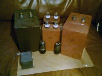
Here's a pic. Sorry about the quality, my camera is at my girlfriends place so I used my phone in poor lighting.
The tubes are 6V6GTs for size comparison.
The big ones are 100µF / 3000V, the mid sized ones are 50µF / 1000V, and the small one is MBGO 20µF / 400V.
The big ones are for the amp's finals' supply (1100V regulated), the mid sized for the driver stage (600V regulated) and the small one (I've got a bunch of these) is for the amp input / DAC output stage (250V regulated).
I'm gathering parts and making plans to one day build a monster of an amp; optical digital input, three fully balanced tube stages finally putting out 1200VPP direct drive to ESL speakers and headphones. Maybe add a switch-in parafeed OT also, at the driver stage.
The big caps do weigh quite a bit. Maybe a little bit more than most PTs I have.
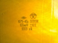
The label pic is hard to read, but it says K75-40a 3000B 100mkF +-10%
Here's a pic. Sorry about the quality, my camera is at my girlfriends place so I used my phone in poor lighting.
The tubes are 6V6GTs for size comparison.
The big ones are 100µF / 3000V, the mid sized ones are 50µF / 1000V, and the small one is MBGO 20µF / 400V.
The big ones are for the amp's finals' supply (1100V regulated), the mid sized for the driver stage (600V regulated) and the small one (I've got a bunch of these) is for the amp input / DAC output stage (250V regulated).
I'm gathering parts and making plans to one day build a monster of an amp; optical digital input, three fully balanced tube stages finally putting out 1200VPP direct drive to ESL speakers and headphones. Maybe add a switch-in parafeed OT also, at the driver stage.
The big caps do weigh quite a bit. Maybe a little bit more than most PTs I have.
The label pic is hard to read, but it says K75-40a 3000B 100mkF +-10%
Attachments
- Status
- This old topic is closed. If you want to reopen this topic, contact a moderator using the "Report Post" button.
- Home
- Amplifiers
- Tubes / Valves
- PSU inrush current