Are there any advantages to powering the 6SL7 with DC instead of AC?
yes, lower hum noise if you use DC
Link does not work!How it sounds @ very low voltage (35Vcc) with ECC82 and line transformer as OPT
https://www.youtube.com/watch?v=V1F7q249M0I
stereo version @ 50 Vcc with 6FQ7 and line transformers as OPT
https://www.youtube.com/watch?v=nsDtAaK5qss
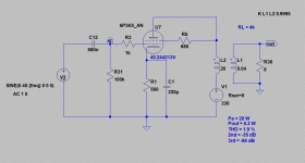
If you want to improve performances of this circuit, increasing output power and decreasing distortion at Hi-Fi level, this is the modified schematic.
The plate voltage of the PL504 has been increased at about 110Vdc (Caution, dangerous voltage!) and there is a global negative feedback to linearize bandwidth and decrease total distortion.
T.b.d resistor should be verified sperimentally to obtain about 90 Vdc on the 47 uF capacitor.
The two output transformers are Hammond 119DA
Hammond Mfg. - "Classic" 600 Ohm - Speaker Matching Transformer - Hammond P/N 119DA
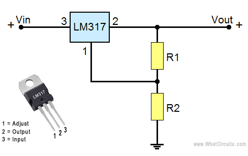
Note: LM317 needs a generous heatsink.
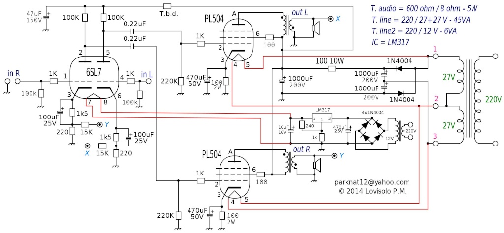
Top Level 600 ohm audio transformer :
TU020
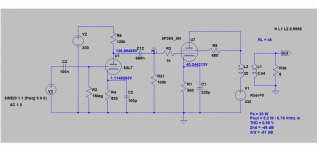
The plate voltage of the PL504 has been increased at about 110Vdc (Caution, dangerous voltage!) and there is a global negative feedback to linearize bandwidth and decrease total distortion.
T.b.d resistor should be verified sperimentally to obtain about 90 Vdc on the 47 uF capacitor.
The two output transformers are Hammond 119DA
Hammond Mfg. - "Classic" 600 Ohm - Speaker Matching Transformer - Hammond P/N 119DA
Note: LM317 needs a generous heatsink.
An externally hosted image should be here but it was not working when we last tested it.
Top Level 600 ohm audio transformer :
TU020
An externally hosted image should be here but it was not working when we last tested it.
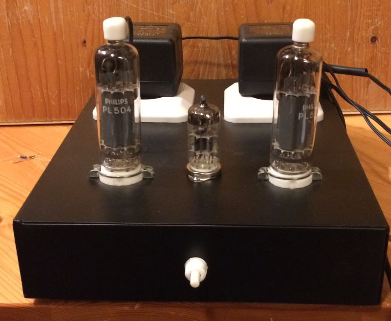
I have also built this amp, with some adaptations:
A PCC85 + 2 PL504's make 63V @ 0.3A in series. Two thriftshop HP 32V printer switched power supplies (the non-grounded versions, otherwise you have a common ground with the power ground) at 64V with anode power to spare, and yes, it sounds great.
Two obsolete Christmas 24V transformers as output trans.
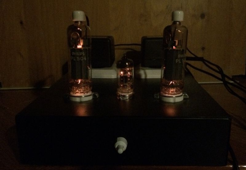
What does this look like?
and (glow in the dark)
Michel
A PCC85 + 2 PL504's make 63V @ 0.3A in series. Two thriftshop HP 32V printer switched power supplies (the non-grounded versions, otherwise you have a common ground with the power ground) at 64V with anode power to spare, and yes, it sounds great.
Two obsolete Christmas 24V transformers as output trans.
What does this look like?
An externally hosted image should be here but it was not working when we last tested it.
and (glow in the dark)
An externally hosted image should be here but it was not working when we last tested it.
Michel
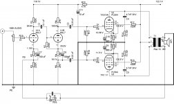
I just built this one up on proto-board with a 6n23p driver and it has surpassed my expectations in every way (no hum or bad noises). For output I tried a whole bunch of PT's in the range of 120v-12v with mixed results. Small toroids worked best (highest output) for frequencies above 100hz, most of the IE transformers I tried seemed to saturate at about half volume but I did find one pair (Yorkville 120v-15v, 60w) that really sound nice! I'm not sure exactly where it's rolling the bass off yet, but my ears are saying 'fullfrequency', loud and clear. Compared to a class d PAM8403 2X3W amp it's a little more powerful and actually pushes my big sub a bit better when I tried it out. These PL504's at $4 a pop are pretty impressive. This schematic makes a pretty nice near field amp! I'll definitely make a nice shell for it and use.
TM
TM
...I should mention that B+ is only 54v derived from a step-up converter. The driver filament runs off a step-down converter so in the end this amp will run off batteries or computer PSU at any voltage between 8-30 volts. I can use it in my trailer or off-grid cottage which is a major bonus.
TM
TM
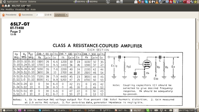
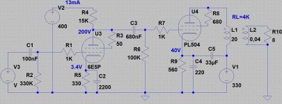
As I wanted to test an 1K Raa output transformer, I decided to quickly built an amplifier which requires a low impedance output transformer. For this I adapted the schematic of the PL504 SE, proposed by Pilovis, for use in a PP amplifier. I used one half of the 6SL7 as pre-amplifier and the other half as cathodyne phase splitter. The PS is more or less similar to that of Pilovis and supplies 120V.
After some experimentation, the anode resistor of the first half of the 6SL7 was set at 150K and a cathode resistor of 4.7K was used. This setting allows for 30 fold amplification with V out of max 9.1V. This gives enough amplification to allow for feedback as well.
For the cathodyne phase splitter (V1B) a number of different resistor settings were tested (see table below), but the best results were obtained with an anode and cathode resistor of 47K, a grid resistor of 470K and a cathode bias resistor of 1.5K. In this setup the DC voltages over the anode and cathode resistors were both equal, each being 19.1VDC.
6SL7 Cathodyne Phase Splitter Test Results with 119V Supply Voltage
Ra and Rc 47K 47K 47K
R cathode bias 4.70K 2.35K 1.57K
Voltage over Ra and Rc 12.5 13.2 19.1
The PL504 tubes are pentode connected and have a cathode resistor of 100R, which is decoupled by an electrolyte of 680 uF 16V. The 10 – 11 VDC on the cathodes implies that each tube draws between 104 – 113 mA.
The G2’s are connected with 100R resistors to the power supply and draw some 11-12 mA each.
The feedback resistor was set at 7.5K (two 15K resistors in parallel).
The amplifier was tested using a function generator set to produce 1000 Hz square waves, which were verified with an oscilloscope. Ringing could be effectively suppressed by adding a 330 pF capacitor across the 7.5K feedback resistor (64 kHz) and a Zobel network in the anode leads of the PL504 connected to ground, consisting of a capacitor of 4.7 nF (2KV) and a resistor of 1K (4W) resistor in series (34 kHz). After these additions the square waves looked good for such simple amplifier.
The amplifier sounds surprisingly well, has a nice punch to it and can play rather loud. It should be able to produce some 4-6 Watts of audio power before distortion kicks in.
As an alternative output transformer one could use a toroidal power transformer of some 10 – 15 VA capacity with two 110 VAC windings used for the 2 primaries and two 9 VAC windings, which are placed in series, to connect the 8 Ohm speaker. This will result in a primary impedance of 1200 Ohm.
Enclosed the schematics
Attachments
Minimalistic spud stereo amp
Here is another simple stereo amp that uses only two tubes, yet needs only 300 mV signal for 2x6 W output: https://frank.pocnet.net/sheets/127/5/50FY8.pdf Output transformer 1 for this amp: Basler Tube Amp Output Transformer 4500 Ohm CT To 4,8,16 Ohm 40 Watt BE32748001 | eBay Output transformer 2 is a line-matching transformer.
Here is another simple stereo amp that uses only two tubes, yet needs only 300 mV signal for 2x6 W output: https://frank.pocnet.net/sheets/127/5/50FY8.pdf Output transformer 1 for this amp: Basler Tube Amp Output Transformer 4500 Ohm CT To 4,8,16 Ohm 40 Watt BE32748001 | eBay Output transformer 2 is a line-matching transformer.
I have got best results with 6P36S, a soviet version of PL504-family tube. Also 6P41S works quite similarly, but must be used with lower Pa.
Practice has shown that 6P36S can be used at >20 W dissipation level.
This is easy to understand, if the size of 6P36S is compared with, for example EL34.
With triode at some 280...300 V anode voltage (+Ub 320...340V) and some 70 mA anode current will produce 5...6 W.
Suitable load impedance is 4k...5k.
Thank you very much!
I would like to build a SET amplifier, because it is still missing from my collection...")
What do you think about the sound quality of the PL504 and the relatives of this tube?
Maybe a parallel version would be nice to reach the 8W power limit what I need...
Greets:
Tyimo
I would like to build a SET amplifier, because it is still missing from my collection...
What do you think about the sound quality of the PL504 and the relatives of this tube?
Maybe a parallel version would be nice to reach the 8W power limit what I need...
Greets:
Tyimo
With UL-connection 8 W may be possible, but there is no big difference (< 2 dB) between 5.2 W and 8 W in practice.
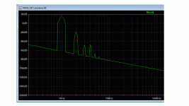
Concerning the triode output stage, here are the simulation and schematic.
Does not that distortion spectrum look musical ?
Concerning the triode output stage, here are the simulation and schematic.
Does not that distortion spectrum look musical ?
Attachments
Thanks!
How would you drive this stage?
The 5th harmonic a bit higher than I like....
How would you drive this stage?
Yes! Looks a typical SE Class A ...Does not that distortion spectrum look musical ?
The 5th harmonic a bit higher than I like....
How would you drive this stage?
This way.
But now 2nd harmonic is canceled so that THD is only 0.55 %. Is this already too low ?
Attachments
Last edited:
of course not!But now 2nd harmonic is canceled so that THD is only 0.55 %. Is this already too low ?
Perhaps it will not be too sterile sounding....
Hi Artosalo! Happy new year!
Could you please check this design? If possible, post the Ltspice tube data for later attempts?
Thank you!
Attachments
Well, this is very nicely done, since I have a lot of PL36s and few of 6H9C I want to attempt this, but can you generally give me advice how to avoid oscillation in any amp? Because, whenever I build something with tubes over the weekend quickly it oscillates and makes funny noises, my soldering skill is ok, but element layout under the cover is just awful, and how to correct it, and how to connect it so that I avoid oscillation?
- Home
- Amplifiers
- Tubes / Valves
- Low Voltage (60V) Stereo Tube Amplifier for Dummies (2+2W)