I just got a pair of PL504s and I happened to land here when googling.
Can I just use the power amp section without 6sn7?
I don't have any dual triode at hand. All that I have is a pair of 6J1 Chinese tubes,which is generally used in low voltage Chinese preamps in triode mode.
Also, I happened to see one schematic by Kainka which uses just 27 volt and a single PL504 ( no preamp tube). Any suggestions?
Hello tnvijay.
With 2 x PL504 and 2 x 6J1 you can build an single ended amplifier.
The 67J1 is not necessairily a low voltage tube. I've seen schematics in which it is used
with power supply voltages ranging from 28 Volts to 275 Volts.
Technically you can use the PL504 without a preamplification tube.
That however means that you seriously limit the power out of the PL504.
The PL504 needs a signal oin G1 of approx 10 Volt to reach full amplification.
You will need some extra signal if you want to apply feedback from the secondary of
the output transformer.
A CD player will give you a signal of say 0.15 - 0.50 Volts. You need to amplify this signal
at least 20 - 67 times to reach the required driving voltage.
The 6J1 is a pentode tube and these can easily do this.
The 6J6 is more or less similar to 5654, 6AK5 and the EF95
Check the spcs of the 6AK5 to find details on the this tube.
The first steps when building an amplifier is to decide on:
The tubes you want to use - in your case I guess 6J1 and PL504
The power supply voltage you plan to use.
How you want to supply the filaments of the tubes.
The PL504 needs 27 Volt 0.3 Amp and the 1J6 6.3 Volts with 0.17 Amp.
You can thus choose to supply the PL504 with 24 - 27VAC in parallel and the
1J6 with 6.3 VAC in parallel. That however requires two transformers.
Other possibility is to put the 2 PL504's in series and the 6J1 in in parallel to get a heater supply chain of 27+27+6.3 VAC = approx 60 V. This voltage could be obtained by rectifying 24+24 VAC. 48V x 1.4 = 67.2 VDC. This is a bit more than needed, but by adding some resistance in the heater chain will reduce the voltage sufficiently e.g. 22 Ohm 5 Watt.
When you use a voltage doubler on the 2x48VAC you will get approx 134 VDC for the power supply. Should work.
Hello tnvijay.
With 2 x PL504 and 2 x 6J1 you can build an single ended amplifier.
The 67J1 is not necessairily a low voltage tube. I've seen schematics in which it is used
with power supply voltages ranging from 28 Volts to 275 Volts.
Technically you can use the PL504 without a preamplification tube.
That however means that you seriously limit the power out of the PL504.
The PL504 needs a signal oin G1 of approx 10 Volt to reach full amplification.
You will need some extra signal if you want to apply feedback from the secondary of
the output transformer.
A CD player will give you a signal of say 0.15 - 0.50 Volts. You need to amplify this signal
at least 20 - 67 times to reach the required driving voltage.
The 6J1 is a pentode tube and these can easily do this.
The 6J6 is more or less similar to 5654, 6AK5 and the EF95
Check the spcs of the 6AK5 to find details on the this tube.
The first steps when building an amplifier is to decide on:
The tubes you want to use - in your case I guess 6J1 and PL504
The power supply voltage you plan to use.
How you want to supply the filaments of the tubes.
The PL504 needs 27 Volt 0.3 Amp and the 1J6 6.3 Volts with 0.17 Amp.
You can thus choose to supply the PL504 with 24 - 27VAC in parallel and the
1J6 with 6.3 VAC in parallel. That however requires two transformers.
Other possibility is to put the 2 PL504's in series and the 6J1 in in parallel to get a heater supply chain of 27+27+6.3 VAC = approx 60 V. This voltage could be obtained by rectifying 24+24 VAC. 48V x 1.4 = 67.2 VDC. This is a bit more than needed, but by adding some resistance in the heater chain will reduce the voltage sufficiently e.g. 22 Ohm 5 Watt.
When you use a voltage doubler on the 2x48VAC you will get approx 134 VDC for the power supply. Should work.
Hello,
Many Thanks for the detailed answer. I am very new to tube electronics and this is infact my first valve Poweramp attempt. All help is very much appreciated. Yesterday I quickly did a wiring and checked the Kainka circuit. I just used one pl504, voltage was 50 volt, 0-24 trafo ( doubler). Filament voltage was by another seperate trafo, about 21 volts. The output vtrafo is a 100 volt line matching trafos, and I used the 10 watt tap( approximately 1000ohm impedance)..My audio source was a laptop. I was surprised by the music quality,even with cheap output trafos. It gave adequate bass and reasonably good highs. But, as you rightly said,the volume was indeed too low. I Had to keep my ears near the speaker box to listen.
Your detailed answer made me understand clearly now. I want to use low power,say 60 volt, as the designer pilovis suggested, and It will be helpful if you can show me some 6j1 circuit which can operate at 60 volts. I have seen Chinese preamp circuits which operate at +/-32 volts and provide 10 times gain. But to achieve 60 times gain, I am not sure of the voltage and other component values.
I was lucky to have a pair of PCL 86. I always wanted to do one amplifier with PCL86, but the output trafo with 5k impedance is not available readily in my place, and importing costs huge money. The main reason I am sticking with PL504 is, this design works with low cost line transformers and I am able to get atleast 10 tubes of PL504 at 3usd each. I would like to stock those for future projects.
Btw, Can I get it to work if I use the triode section of PCL 86 ? I have read that it's a 12AX7 or Ecc83.
Finally, my present setup is a JLH 69 at 5+5 watt. Can I expect identical volume levels with the claimed 2+2 watts of PL504 schematic?
Many thanks for all the help
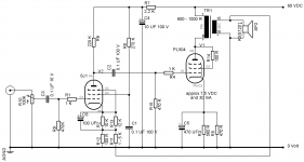
Stereoverstärker mit voer PL504
This is the circuit, I used. Although I used only one PL504 in prototype.
This is the circuit, I used. Although I used only one PL504 in prototype.
A PL504 at 35 to 65 Volt has very little room to produce any output. The tube connected as pentode will also start drawing serious grid current in that area of its working curve.
Nice to play around with, but not to build a serious amplifier. To get any output in the range of 3-4 watts you need to build a push pull PL504 amplifier and you need at least 130 - 150 Volts power supply. Look at the bottom of page 3 of this thread where I posted a schematic of such an amplifier. It also details the output power. Don't forget that speaker boxes with separation filters for the bass, mid range and tweeter also consume part of the power your amplifier produces. Which can cause you not to hear very much. Very low power amplifiers should be listened at using single driver, high efficiency, wide range speakers.
Nice to play around with, but not to build a serious amplifier. To get any output in the range of 3-4 watts you need to build a push pull PL504 amplifier and you need at least 130 - 150 Volts power supply. Look at the bottom of page 3 of this thread where I posted a schematic of such an amplifier. It also details the output power. Don't forget that speaker boxes with separation filters for the bass, mid range and tweeter also consume part of the power your amplifier produces. Which can cause you not to hear very much. Very low power amplifiers should be listened at using single driver, high efficiency, wide range speakers.
When you use a matching transformer as single ended (SE) output transformer (one tube output) you have to realize that the transformer is not only carrying the amplified AC signal, but also carrying the DC current flowing through the tube. With the PL504 at low voltages this may be a considerable current. The DC current can saturate smaller SE output transformers. To counter this in SE output transformers, the laminations are stacked such that these is a gap between the E's and the I's.
Matching transformers are made to deal with AC signals only and do not need an air gap. This makes them not well suited for SE output transformer use.
They could work better as push pull output transformers. In push pull the DC current of two output tubes cancels out each other's magnetization effects. So no air gap is needed.There are some interesting articles on the use of line transformers or matching transformers to be found on internet. An example is here.
http://home.alphalink.com.au/~cambie/6AN8amp/M1115.htm
However the impedances obtained with matching transformers are generally high. This will be too high for PL504 in PP. More suited for PCL86 or EL84's. PL504's in PP like to see an impedance of 2.5 - 3K. A cheap solution to reach this impedance is a to use a toroid transformer of 2x110 (or 115) volt with an output voltage of 2 x 12V (the secondaries in parallel) = approx 2.4K. You can calculate the impedance of a transformer as follows: (prim voltage / secondary voltage )^2 x speaker impedance. The VA rating of the toroid should be at least more than twice the output rating of the amplifier. I think you might find such transformers with Mouser in India, but there might be more suppliers. Again real tube output transformers are best, but they come at a price.
Thanks for the detailed answer. Since i am totally new to tubes, i would like to test the water with simple designs and minimum components. i just have two trafos now, so for a a stereo, i will stick with SE design.As i gain confidence and slowly gather parts, i will try your push pull circuit eventually. The cost of shipping to india is twice that of the trafo itself. Anyway, let me try what i can. My best bet is now to use 6j1,as a driver as you suggested.
i came across a 6j1-fu32 circuit. It uses 82k anode resistor and 2.2k cathode resistor, B+ is 235 volt, which is dropped to 105 volt after 82 k anode resistor.
Thanks again for the help
i came across a 6j1-fu32 circuit. It uses 82k anode resistor and 2.2k cathode resistor, B+ is 235 volt, which is dropped to 105 volt after 82 k anode resistor.
Thanks again for the help
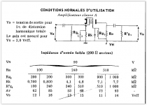
The settings for the 6J1 = 6AK5 can be found in the enclosed table.
This is for a power supply of 90 Volts, but lower e.g. 65 Volts will also work.
The Rk needs to be bridged by a 100 uF capacitor (16V).
The input and output capacitor can be 0,1 uF.
The input capacitor is rated 16V and the output capacitor should be rated more than the power supply voltage on the tube.
Vs / Veff is the signal output voltage of the tube.
Av is the amplification factor.
R'g1 is the grid resistor for the next tube. In your case the PL504.
Attachments
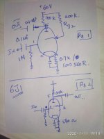
Many thanks for the hand holding. I have been browsing through pages and scratching my head to the basics of valves.With this little knowledge and your table, I have drawn a schematic . I have chosen the first column of the table, for a gain of 62 with voltage output of 12 volt. What I can't understand is in all schematic I have seen, the pin 5 and 6 are tied together and converted to a triode. In the schematic I see G2 is seperately tied to b+ . Hope I am getting things correct.Let me know if whether fig 1 or fig 2 is correct for the preamp section .
Below the schematic I suggest you have a look at.
This is based on the 6AK5 tube data for high impedance inputs at 90V HT
Page 1.3. The resistor values are rounded to the next commerically available value.
https://tubedata.altanatubes.com.br/sheets/020/6/6AK5.pdf
The PL504 is connected as triode. That means G2 is connected to the anode. The 100 R resistor should help to reduce oscillations. Connect close to the socket. A graph of the working point of the PL504 as triode on the last page of the PL504 tube data sheet.
https://tubedata.altanatubes.com.br/sheets/010/p/PL504.pdf
The working point of the PL504 in triode can be found by drawing a horizontal line at 30 mA. This line crosses the vertical line you draw from 60 V. This gives a G1 voltage of -7.5 Volt. Or 7.5 Volt on the cathode, when the G1 is at 0 volt. This implies an anode current of some 30 mA. This might be much for a small output transformer and possibly lead to saturation e.g. distortion. If that is the case you need to increase the value of the cathode resitor, which will lower the current (and the output volume) as you can see from the grapgh.
The 100R and 1K grid resitors (connected to G1) should be soldered as close as possible to the tube socket. They are there to avoid oscillations.
The cathode resistors of both tubes consist of 2 resistors in parallel to get the right value.
Attachments
The feedback resistor of 1 to 5 K may be too small resulting in too much feedback. In normal amplifiers I would use something like 15K, but then thgere is a more output signal. Suggest you first try the amplifier without feedback and later add it. You can then experiment with the value of the feedback resistor.
Theoretically possible. All "P" tubes have a filament current of 0.3 A and can meant to be stringed together in the fillament supply.l For the 6J1 or EF95 this is different. This tube is meant to be used with a fillament supply of 6.3VAC. You also have to check the Vkf value on the data sheet. This is the max alklowed voltage beteen the filament and the kathode. For the EF95 this is 90V. The 6J1 has a filament current of 0.17 A. So if you want to make a string you have to put 2 pcs of 6J1's in parallel. This will give you 0.34 A. You can put that in series with the filament of ONE PL504 (0.3 A). So 6.3 + 27 = 33.3 VAC. This is more than the 31 VAC you measure on your unloaded transformer. When the transformer is loaded this voltage will drop considrably and this solution will thus not work. Another solution is thus needed.
For the filaments you could make a string of resistor 22 Ohm 4W - PL504 - PL504 - 2 pcs 6J1 in parallel. This will suit a supply of 67 VDC. You must carefully check if the voltage from your transformer drops down under load. If that not the case the resistor in the filament heating chain needs to be larger.
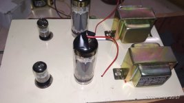
I tried your 6j1 Pl504 schema, as a rough prototype. I don't have sockets for 504, So I drilled on mica sheet and fixed the valve. I immediately got sound on powering on. However,the sound is very much distorted. I removed the cathode bypass cap from 6j1. It dramatically reduced the volume,but the distortion was still present. I tried various cathode resistor with and without cap bypass on PL504. With a value of 100 ohms, and with cap, the sound is little clear, but even then,it's distorted.i tried a feedback resistor of 10k from OPT trafo. But there was no improvement in the sound.
Btw, I get 31VAC from trafo, and when I used a 10 ohm,10 watt series resistor for pl504 filament,the resistor burnt .I ran the filaments at 31 volt,but I am worried about the tube longevity.Any help in fault finding will be much appreciated.The output trafo is a 100 volt line matching trafos, and it gives good mid and high frequencies response. But rolled off lows.
Btw, I get 31VAC from trafo, and when I used a 10 ohm,10 watt series resistor for pl504 filament,the resistor burnt .I ran the filaments at 31 volt,but I am worried about the tube longevity.Any help in fault finding will be much appreciated.The output trafo is a 100 volt line matching trafos, and it gives good mid and high frequencies response. But rolled off lows.
Attachments
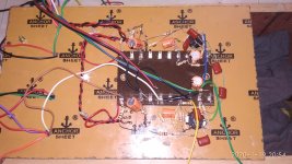
It hard to make up what you have done with your wiring form the pictures you send me.
However I'm a bit worried with the fillament supply. If you run the PL504 on 31 volt than I assume they are both in parallel and thus consume together 0.6 Amp. 31-27 = 4 Volt. You need a 4/0.6 = 6.6 Ohm resistor in series with the PL504 filaments. So a 10 Ohm resistor should be okee. The VA rating is V*A= 4 * 0.6= 2.4 Watt. I double this to be sure. So 5 Watt should work fine. If the resistor burns, you have a short somewhere. If you power on and you see smoke or smell something odd kill the power immediately and start checking your work. Happens to all of us. How do you feed the filamenbts of the 6J1's? 6.3VAC?
I suggest you check (measure) all resistors to see if they are the right value and connected at the right spot.
The other issue may be the way you have connected the Line transformer.
A wrong ipedance matching will distort heavily.
Need to go for dinner will explain later how you have to connect the line transformer.
To see how the impedance of the primary winding of the line matching transformer is calculated see:
http://home.alphalink.com.au/~cambie/6AN8amp/M1115.htm
I've done this calculation for your line transformer on the enclosed spreadsheet.
The connections to use are: 0 - 10W for the PL594 anode and 0 - 8 Ohm for the speaker of 8 Ohm or 0-16 Ohm if the speaker is 16 Ohm. This will give you a primary impedance Z = 1000 Ohms. Which should be fine for the PL504 in SE.
You can verify the speaker impedance bij measuring with an Ohm meter over the speaker terminals. Don't use a speaker box with high mid and low filters. You don't have enough power to do so. Best is a plain 8 Ohm speaker.
First make sure the filaments of the tubes are properly working. To low filament power can also lead to distortion.
- Home
- Amplifiers
- Tubes / Valves
- Low Voltage (60V) Stereo Tube Amplifier for Dummies (2+2W)