It may suck more than you think.
If you read the article in Silicon Chip, it appears to have been designed to use parts that are standard stock items of one of their major advertisers.
The article (October 2014 issue, pages 24 thru 26) states that the transformers are standard 100 Volt line transformers used for building public address, of the sort that have "power" tappings on the primary side. They use the Gnd as one plate load, the 20W tap for the other anode, and the 5W tap to connect to HT.
Last edited:
There must be a zillion people that would love to make a valve amp but the cost and availability of output transformers is a major stumbling block. This amp might just be the thing that gets them going. And the OPTs might be smaller than on some other amps but the proof is in the pudding - it may sound better than some people expect. Anyway, nothing a sub amp wouldn't fix. Besides, there is nothing stopping you from putting on a different set of trannies if you really wanted to. Heck, I've seen some stuff around here modded to the point that there is hardly anything left of the original design.
Besides, there is nothing stopping you from putting on a different set of trannies if you really wanted to. Heck, I've seen some stuff around here modded to the point that there is hardly anything left of the original design.
+1

The info I put in my earlier post about transformer tappings was what I deduced from the intro article in the October issue, and I got 2 tappings reversed by mistake anyway.
The November issue of Silicon Chip has now appeared in newsagents. It has the full circuit and some performance graphs.
The distortion performce is not that good for a an ultralinear amp with 6 tube functions and the low power output of 10 W per channel. THD is claimed around 0.1% to 0.2% depending on level and frequency. Neville Thiele did better than that in a HMV (Australian EMI) design using just two 6BM8's in a Quad-style circuit.
It is interesting what they did for an output transformer. It is a Soanar M1115 100 Volt line transformer intended for building public address. This has tappings of 1.25W, 2.5W, 5W, and 15W.
The Com (100% of one half winding turns wrt to HT) is connect to one anode, the 5W terminal to HT, and the 1.25W tapping (100% of one half winding turns) is connected to the other anode. The 15W tapping (42% of one half winding) is used for the first screen, and the 2.5W tapping (41% of one half winding)
It was found by the inventors of ultralinear, Haffler & Keroes, that tapping around 43% is optimum from the point of view of distortion, for tetrodes, and this was been confirmed by others, eg the Amalgamated Wireless Valve applications laboratory.
However, using 43% tappings puts stringent requirments on the transformer for stability, and many commercial UL amplifers used tappings at lower percentages eg 20%, resulting in slightly more distortion and marginally more power output.
Unfortunatley Silicon Chip have included no waveforms or any information that can be used to assess stability. The maplifier uses lag compensation, which is a simple effective way to address stability, but it may cause transient intermodulation.
The output stage screen resistors are 47 ohm. Many people think that screen resistors are just there to prevent parasitic oscillation. They do prevent it, but it was found by researchers in GEC a long time ago, that as screen gm is curved, you can optimise the screen resistors to futher reduce distortion. The Silicon Chip authors seem unaware of this, and their chosen values are quite low.
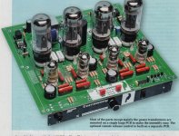
The construction technique is "naked PCB on display", which may offer visual appeal to some, but is a hazard for family use. It will collect dust, and be a hazard to children and even adults who are not electronics trained.
The November issue of Silicon Chip has now appeared in newsagents. It has the full circuit and some performance graphs.
The distortion performce is not that good for a an ultralinear amp with 6 tube functions and the low power output of 10 W per channel. THD is claimed around 0.1% to 0.2% depending on level and frequency. Neville Thiele did better than that in a HMV (Australian EMI) design using just two 6BM8's in a Quad-style circuit.
It is interesting what they did for an output transformer. It is a Soanar M1115 100 Volt line transformer intended for building public address. This has tappings of 1.25W, 2.5W, 5W, and 15W.
The Com (100% of one half winding turns wrt to HT) is connect to one anode, the 5W terminal to HT, and the 1.25W tapping (100% of one half winding turns) is connected to the other anode. The 15W tapping (42% of one half winding) is used for the first screen, and the 2.5W tapping (41% of one half winding)
It was found by the inventors of ultralinear, Haffler & Keroes, that tapping around 43% is optimum from the point of view of distortion, for tetrodes, and this was been confirmed by others, eg the Amalgamated Wireless Valve applications laboratory.
However, using 43% tappings puts stringent requirments on the transformer for stability, and many commercial UL amplifers used tappings at lower percentages eg 20%, resulting in slightly more distortion and marginally more power output.
Unfortunatley Silicon Chip have included no waveforms or any information that can be used to assess stability. The maplifier uses lag compensation, which is a simple effective way to address stability, but it may cause transient intermodulation.
The output stage screen resistors are 47 ohm. Many people think that screen resistors are just there to prevent parasitic oscillation. They do prevent it, but it was found by researchers in GEC a long time ago, that as screen gm is curved, you can optimise the screen resistors to futher reduce distortion. The Silicon Chip authors seem unaware of this, and their chosen values are quite low.
The construction technique is "naked PCB on display", which may offer visual appeal to some, but is a hazard for family use. It will collect dust, and be a hazard to children and even adults who are not electronics trained.
Last edited:
Hi
I was very exited when I saw this new kit, then very disappointed with the output transformer choice.
There are huge choices of output transformers they could have chosen, but I suppose we should make it 1st and see .. suppose we could use as a headphone amplifier?
But lets see if we can do our 1st mod, change out the transformer, I probably will not make it as I have just completed my K8011 90w valve mono block, so I don't see the point
regards
Nick
Never in a million years would I spend all the money required to building an amp with 6L6's and all the supporting solid state stuff they put in, delivering just 10 watts, when I could build an amp with just two television triode pentodes readily available as NOS, that will deliver more power and less distortion. And most likely much better stability. And less transient distortion. Sure you can put in a decent transformer. Put it in a better circuit.
Like I said before, the Silicon Chip is not designed for quality performance. It is designed to use up parts (6L6's, the PA transformers, and the rest of it) that are in stock at their major advertiser Altronics.
Like I said before, the Silicon Chip is not designed for quality performance. It is designed to use up parts (6L6's, the PA transformers, and the rest of it) that are in stock at their major advertiser Altronics.
I was pretty excited to pick up the November issue to learn more about this amp. However as I look at the required parts, I begin to worry about the cost for something with such low performance specs. While it may offer decent bang for buck, it would be a bit risky for myself as a bit of a beginner to put that kind of cash down on something I could fry if I were to make a simple mistake.
Keit; do you have any links to schematics/diagrams/guides that would help educate a beginner on how to construct something like what you have described?
Keit; do you have any links to schematics/diagrams/guides that would help educate a beginner on how to construct something like what you have described?
Likewise I rushed out and bought the Silicon Chip issue.
The use of the line output trannsformer is something Aussie guys have been doing for some time for guitar amps (see the "Lamington").
The design has many more serious problems than the output transformer. The phase splitter design (for example) is seriously bad. When I looked at the splitter circuit values I believed there must have been some typo's in preparing the schematic but on reading the article it appears not, it is just a bad design (It is a differentail splitter with 6K8 tail and 120K (grid driven side) and 220K (cathode driven side) anode loads.
1M grid leaks on the 6L6 Output tubes which they get away with because the outputs are cathode biased and run at very low power (10W per channel). Global feedback is around too many stages and is rediculously high, dragging the overall gain back to less than 8.
The editor (Leo Simpson) has always said that he would never publish a valve amp design. Now we know why, because they are seriously bad at it.
What a disappointment.
For Aussie readers who want an Aussie designed 10W per channel valve (tube) amp that would leave this design for dead l have no hesitation in self promotion by recommending the Baby Huey instead. Parts cost would be very similar or less.
Baby Huey PP EL84 amplifier - diyAudio
I woud use "real" output transformers. ST35 trannies are available at reasonable prices (from the US) and for cheap output trannies these are not too bad.
86PP output transformer
Bob has some of these in stock.
http://stores.ebay.com.au/Bobs-Tube-Audio
My everyday home amp is an enhanced version of that design, (fixed bias outputs, mosfet source follower buffer between input diff amp/splitter and the output tubes).
Post #602 schematic here:
http://www.diyaudio.com/forums/tubes-valves/72536-el84-amp-baby-huey-61.html
Power Supply is post #603
Post #604 is a variant I later abandonned.
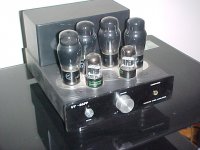
Picture attached, I'm using 6V6G from the Sydney AWV factory with 6SL7 front end. The chassis is from MabelAudio too.
Cheers,
Ian
The use of the line output trannsformer is something Aussie guys have been doing for some time for guitar amps (see the "Lamington").
The design has many more serious problems than the output transformer. The phase splitter design (for example) is seriously bad. When I looked at the splitter circuit values I believed there must have been some typo's in preparing the schematic but on reading the article it appears not, it is just a bad design (It is a differentail splitter with 6K8 tail and 120K (grid driven side) and 220K (cathode driven side) anode loads.
1M grid leaks on the 6L6 Output tubes which they get away with because the outputs are cathode biased and run at very low power (10W per channel). Global feedback is around too many stages and is rediculously high, dragging the overall gain back to less than 8.
The editor (Leo Simpson) has always said that he would never publish a valve amp design. Now we know why, because they are seriously bad at it.
What a disappointment.
For Aussie readers who want an Aussie designed 10W per channel valve (tube) amp that would leave this design for dead l have no hesitation in self promotion by recommending the Baby Huey instead. Parts cost would be very similar or less.
Baby Huey PP EL84 amplifier - diyAudio
I woud use "real" output transformers. ST35 trannies are available at reasonable prices (from the US) and for cheap output trannies these are not too bad.
86PP output transformer
Bob has some of these in stock.
http://stores.ebay.com.au/Bobs-Tube-Audio
My everyday home amp is an enhanced version of that design, (fixed bias outputs, mosfet source follower buffer between input diff amp/splitter and the output tubes).
Post #602 schematic here:
http://www.diyaudio.com/forums/tubes-valves/72536-el84-amp-baby-huey-61.html
Power Supply is post #603
Post #604 is a variant I later abandonned.
Picture attached, I'm using 6V6G from the Sydney AWV factory with 6SL7 front end. The chassis is from MabelAudio too.
Cheers,
Ian
Attachments
Keit; do you have any links to schematics/diagrams/guides that would help educate a beginner on how to construct something like what you have described?
As you live in Australia, obtain the Radio TV & Hobbies DVD, which has the complete set of Radio TV & Hobbies magazine. It's advertised in Silicon Chip & should be avialable to order on their website.
Study the Playmaster tube amps in RTV&H, particularly the ultralinear versions published in the later 1950's. No detailed specs were given, and the design emphasis was on low cost and not the best possible performance, but these tube amps were quite competently designed and give a good account of themselves. The trasnformers for them are still in production at not TOO much cost. Unfortunately the solid state amps published in RTV&H by then renamed Electronics Australia were not competently designed. Some of their SS amps were dreadful.
When you are familiar with the amps in RTV&H , it will be time for you to move up to designs where low cost was not the design emphasis.
The best tube amps produced in the 1950's and for which full constructional info and engineering philosophy is available is the series of KT66/KT88 ultra linear amps and preamps designed by GEC eg the GEC 88-50. Info on these is availble on the www - if nobody else does, I will post whereabouts later.
Equally good amps were made by certain weel regarded American manufactuers, but I haven't found where to get full engineering info for them yet, only circuit diagrams and service manuals.
Some folk recommend the Mullard 5-10 amps for beginners. I don't, as the Playmasters were just a bit better, and there is more info available for them.
It's worth studying articles on neg feedback written by Cathode Ray (M G Scroggie) and S W Amos in the magazine Wireless World in the 1950's and early 1960's. That will make it crystal clear for you why it is that:-
1) Negative feedback makes amps sound better
2) and more feedback makes amps sound better still
but
3) only if the designer knows what they are doing, or they are very lucky
Unfortunately Wireless World is not available on the WWW except for a few scattered issues. Also, Cathode Ray's writing style is very old fashioned cf today's authors and it's wordy. You'll need to go to your State Library, but I promise you, it will be well worth the time and trouble.
You may have gathered from my various posts that I am not in favour of surrounding tubes with lots of silicon. It just isn't necessary, and it juts adds lots of stuff to go wrong. It conflicts with the aesthetic of a tube amp. A nice well built tube amp with carefuly chosen parts, paint scheem and metal finish looks nice as well as sound good, visitors remark on it, and there's nothing wrong with all that. Silicon on PCB just looks ho hum.
It is apparent that others on this forum disagree.
I have to go do some paying work now, I will put up Neville Thiele's tube amp when I get the time.
Last edited:
For info:
The Historical Radio Society of Australia (which we affectionately call the "Hysterical" Radio Society of Australia) published an Index of Technical and Construction Articles for Radio TV and Hobbies and its successor Electronics Australia.
It is here:
Historical Radio Society of Australia - web site
It will help you find what you want.
I have a copy of that Radio Television and Hobbies CD (April 1939 to June 1965) - it is well worth the $60 or so purchase cost - anyway I claimed its cost on my tax return.
Plus you will get a real chuckle out of some of the propaganda articles from the 2nd WW years.
Cheers,
Ian
Last edited:
Ah, but the 6L6's have one advantage for Silicon Chip in nominating them, the same advantage that the M1115 line transformers have: It keeps them in the good books with their major advertiser Altronics, who have large stocks of these devices. The amp may get the punters to go and buy 6L6's under Catalog No. Z1395 at $82.00 a pair.
Note that they could have chosen EL34's, but at Altronics they are a cheaper price. Heck, for only 10 watts, EL84's are plenty good enough, and Altronics have them too. But only $20.50 - not much profit cf 6L6.
Note that they could have chosen EL34's, but at Altronics they are a cheaper price. Heck, for only 10 watts, EL84's are plenty good enough, and Altronics have them too. But only $20.50 - not much profit cf 6L6.
Thanks for the thorough, lengthy outline, Keit! I might have to suggest the Radio TV & Hobbies to my fiance as a stocking stuffer.
I'm looking to build some useable, worthwhile equipment while learning the underlying theory and best practice. Going back to the beginning of hi-fi audio design definitely seems like a good place to start. At the moment I'm building the Silicon Chip ULD-Mk3 kit just for something to do and to refine my soldering skills. This kit benefits me at the moment as it is modular, so I can buy a few parts at a time rather than pay one up-front cost. The instructions are also quite thorough and easy to follow. I realise this amplifier gets mixed reviews, but it seems they can be made into solid performers with some minor tweaks. The trade off is that I'm just following directions without applying much thought to it. Going through some historical valve designs should be a good way to grasp the underlying theory.
Anyway, I look forward to seeing Neville Thiele's tube amp if you get the time to upload it. Thanks again!
Remember Grant, these are the guys who put out a LINESTAGE which used a 12AX7 fercrissakes, presumably with masses of NFB to get the output impedance down to 1.5k and gain down to relatively sane levels.
But never mind
'We had to brush up on valve design to do it but the performance has turned out to be quite impressive, better in fact, than was commonly achieved when valves ruled the electronics world'.
It's good to know a local magazine can put out designs which sit at the cutting edge of audio. Onya Leo...
- Home
- Amplifiers
- Tubes / Valves
- Silicon Chip mag "Currawong" amp