Hi,
I'm wanting to try this circuit for an amplifier that has regulated C and un-regulated B supplies. Perhaps using 6CG7 instead of the 6F8's.
Wanting to know if anyone has experience with this or similar other circuits. My main hesitation is the high impedance AC loop of the output stage, I was always of the impression that low impedance loop was more desirable.
Lowest AC loop impedance from filament CT to grid appears be Z.ac of the -200V supply final shunt (VR) plus 200k ..
Any comment welcome.
Thanks,
Shane
Attachments

Last edited:
...My main hesitation is the high impedance AC loop of the output stage,...
That is a pure DC-circuit.
What AC loop do you actually mean ?
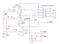
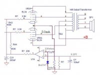
I just join in the discussion. I look at the schematic, it's very complicated. If your goal is the regulate the idle current of the power tubes, this is a circuit I come up with for the fun of it and see whether that suit your needs.
I just use an example of 50mA idle current between the two tubes. The current is set by the 0.5mA into the 1K resistor( I made a mistake, it should be 100 ohm). Take a look at Ti OPA454. The +V can be about +3V which you can rectify from a center tapped filament winding. -V can be rectified from the -bias tap of the PT.
The dominant pole of the closed loop is by the RC of 20K and 220uF cap. You can increase the value to lower the pole frequency. The regulation can be very slow....into a few seconds. So you can make the pole frequency so low that it's totally out of the way.
This is just an idea for you the think about.
Attachments
Last edited:
To keep the average and quiescent current the same yuo have to cut of the cause of the difference.In classA no problem but when the amp goes in classB the negative side of the current can't go deeper then ground but the positive side still goes up and so does the average.By blocking the measured current at twice the quiescent you take away the same amount on both sides.The schotttky diode conducts at more or less 0.3V so the cathode (measuring) resistance has to drop 0.15V for 50mA.
Mona
Mona
Attachments
I am so pleased that we have moved on from hideous circuits like the main one shown. The way I set up auto bias is by way of measuring the plate current of each individual power valve after the amplifier has been on for a short while and under no signal conditions. So, I set an approximate bias voltage, (to safeguard against excessive plate dissipation) to start with. The amplifier is switched on, warms up for about 2minutes. My circuit then mutes any input signal and detects the plate current, via a cathode resistor. For class A I look for 45mA in each cathode and if low, increase the bias voltage accordingly. When all valves are biased, the system holds the values and un mutes the amplifier. The bias detect looks at the cathode current every time there is no signal. If required one can easily set up with a zero crossing detector to check the bias at each zero signal point but I don't think there is any need and it will detract from the nice compression effect that valves give us.
For those familiar with CRT white level, you will know exactly what I mean.
For those familiar with CRT white level, you will know exactly what I mean.
Thanks for the the replies.. I should have mentioned the circuit would be for an IT coupled PSE amplifier with fixed bias.
The output stage is unregulated, the bias supply is regulated. All I'm wanting to do is have the bias voltage counter any change in B supply voltage = plate current.
@artosalo - the AC audio signal
@oshifis - SE OP stage.. I'm ok with pot and meter if it comes to that.. but looking.
@alan0354 - thanks for the schematic and in the info, I'm wanting to use a tube..
@DF96 - as a means to have it counter a change in plate current only, acceptable ?
Thanks again.
Shane
Automatic bias supplies are usually unnecessary, but sometimes used by people who wish to get the bias exactly right. This design guarantees that only for zero signal. A simple bypassed cathode resistor would be better, more accurate, when signal is present.
If your concern is the unregulated supply rail (presumably varying with mains voltage variation) then the answer is a fixed negative bias - also unregulated so the two vary together.
If your concern is the unregulated supply rail (presumably varying with mains voltage variation) then the answer is a fixed negative bias - also unregulated so the two vary together.
I have been thinking on and off a little about this. I really cannot think of an analog way of doing auto control of ONLY the idle current but not affecting the operating condition. The only think I can think of so far is using a uP control. Monitoring the input, if there is no input for say 10 seconds ( say between songs), then read the idle current and adjust the grid bias voltage with a DAC. There are plenty of embedded processor that has build in mux ADC and DAC with EEPROM and RAM. You program vs I^2C bus.
Bottom line, you need intelligence to detect the idle condition and adjust. This will work as the drift of the idle current with fix grid voltage should be very slow......into minutes, hours or even days. Programming should be super easy.
BUT, do you really want to do that? I've seen a Conrad Johnson power amp that the guy adjust the bias with a tweeker from time to time!!!! Do you really think you can hear the difference if the tube is bias at 30mA and it drift off 3mA?
Last edited:
u-Controllers are used in a multitude of places. They are very powerfull and do what they are programmed for.
But there the probleims arise...
What happens after, let's say 10 years; a defect in the u-processor part, other values that have to be programmed and the source code is lost.
This is true for all these application that can be handled via traditional analog electronics.
I have the impression that a many of electronic developers who use mainly u-controllers are not able to think analog.
Exception there are of course...
This is a very nice excercise in classical analog thinking and design.
Simplicity is in many cases a good answer. Have a look at #10 (JonSnell)
I'm looking for a option to suit an amplifier that I have..
The bias supply is regulated, because the input stage sets up with split rail B with -40V at the plate which is DC to the following stage grid. That is input to driver, which is then IT coupled to the output stage. The secondary of the IT is referenced to the regulated -ve rail. Free lunch, low impedance, low noise.. no big caps.. CCS fed VR tube.
So the question is not about the merits of cathode vs fixed bias, nor about unregulated C supplies and explanations about line voltage fluctuations and plate current vs grid bias.
Thanks to Alan0354 for remaining on topic. Its not so much an issue, but when I saw the original schematic, I did wonder how applicable it might be. From the replies, it seems panel meter and pot is probably good enough.
Thanks all, case closed.
Shane
u-Controllers are used in a multitude of places. They are very powerfull and do what they are programmed for.
But there the probleims arise...
What happens after, let's say 10 years; a defect in the u-processor part, other values that have to be programmed and the source code is lost.
This is true for all these application that can be handled via traditional analog electronics.
I have the impression that a many of electronic developers who use mainly u-controllers are not able to think analog.
Exception there are of course...
This is a very nice excercise in classical analog thinking and design.
Simplicity is in many cases a good answer. Have a look at #10 (JonSnell)
When comes to uP control, documentation is of utmost importance. Yes, you can no longer read schematic and back analyze the circuit. I actually have more experience with this kind of control system than tube amps!!! It is not that hard, just a different mentality. I agree most of the people that design uP don't know much of analog electronics. For me, I designed the hardware part only and let others to program.
Not necessarily. An analogue gated sample-and-hold circuit could do it.Alan0354 said:Bottom line, you need intelligence to detect the idle condition and adjust.
Pick up a copy of van der Veen's High-End Valve Amplifiers 2. He presents several analog solutions. Also don't forget TubeCad: Amplifier auto bias circuits: Broskie auto-bias circuitI have been thinking on and off a little about this. I really cannot think of an analog way of doing auto control of ONLY the idle current but not affecting the operating condition.
Pick up a copy of van der Veen's High-End Valve Amplifiers 2. He presents several analog solutions. Also don't forget TubeCad: Amplifier auto bias circuits: Broskie auto-bias circuit
That works for Class A SE, same reason the circuit I posted should work for SE class A also as it's a low pass filter and use the symmetric nature of AC signal. But does the circuit in the article work for push pull power amp like what I drawn because the waveform at the cathode note is asymmetrical?
Last edited:
Not necessarily. An analogue gated sample-and-hold circuit could do it.
Yes, I thought of S/H, but the circuit can get complicated and particular how do you choose the sampling point? You have to wait for the dead time to sample. The uP circuit is very simple. One uP like the Analog Devices ADuC821 from my days ( 10 years ago), a quad opamp and some other components will do it.
Software, software, software.
One day you or another owner will not remember de details.
All that u-controller stuf will not last.
Utterly rubbish.
Allthough: my respect to the writers of the sw.
I did it for allmost 20 years and I'm so glad that I whas able to turn my back to these black boxes. Long live the analog world. Long live the simple gates.
Projects made 35 years ago are still repairable. In the event a part is no longer available; a substitute or a hardware change is possible.
And no schematic?
Reverse engineering can be done.
With a u-controller? Bye Bye!!!
Cheers
Yes it works for class AB.That works for Class A SE, But does the circuit in the article work for push pull power amp like what I drawn because the waveform at the cathode note is asymmetrical?
- Status
- This old topic is closed. If you want to reopen this topic, contact a moderator using the "Report Post" button.
- Home
- Amplifiers
- Tubes / Valves
- DC Automatic Bias Control - Auto fixed bias