First off I'd like to recognize PMillet for the excellent write up on his "807" Push-Pull Amp that is the inspiration for this project.
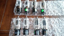
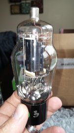
I recently picked up 8 used and reasonably well matched 6BG6G tubes.
The glass is nice and clear with bottom getter, they really are beautiful.
I have been doing a bit of research lately about the 807 PP amps I have been able to find out there.
I came across the 807PP amp from PMillet and I really like the idea of using his driver and PCB boards with my monoblocks.
However his design shows about 40W before clipping with 807ish tubes in PPP.
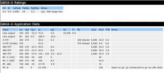
The Ducan TDSL sheet shows AB1 PP for 6BG6 at 450Va, 400Vg2, -37Vg1 giving 55W out on a 5.6K OPT w/ 1.8% THD.
I would like to take this info and build a PPP 6BG6 at those voltages.....what kind of power out can I expect and what would be a reasonable OPT value to use 3.5K???
I'd like around 100W monoblocks, is this a reasonable expectation?
I'd like to stick with Edcor transformers all the way around except the chokes which will most likely be Triad.
I am not opposed to using Valve Regulators to get the miscellaneous voltages I need I actually think they are kinda cool.
Any input would be MUCH appreciated, this will be a semi-long term project because I don't want to cut corners on quality to a reasonable extent.
I will be building these as Monoblocks so I know I will need about 6A on the 6.3V heater and I will be using tube rectification instead of SS, I may consider hybrid rectification if there is a good enough argument for it.
I recently picked up 8 used and reasonably well matched 6BG6G tubes.
The glass is nice and clear with bottom getter, they really are beautiful.
I have been doing a bit of research lately about the 807 PP amps I have been able to find out there.
I came across the 807PP amp from PMillet and I really like the idea of using his driver and PCB boards with my monoblocks.
However his design shows about 40W before clipping with 807ish tubes in PPP.
The Ducan TDSL sheet shows AB1 PP for 6BG6 at 450Va, 400Vg2, -37Vg1 giving 55W out on a 5.6K OPT w/ 1.8% THD.
I would like to take this info and build a PPP 6BG6 at those voltages.....what kind of power out can I expect and what would be a reasonable OPT value to use 3.5K???
I'd like around 100W monoblocks, is this a reasonable expectation?
I'd like to stick with Edcor transformers all the way around except the chokes which will most likely be Triad.
I am not opposed to using Valve Regulators to get the miscellaneous voltages I need I actually think they are kinda cool.
Any input would be MUCH appreciated, this will be a semi-long term project because I don't want to cut corners on quality to a reasonable extent.
I will be building these as Monoblocks so I know I will need about 6A on the 6.3V heater and I will be using tube rectification instead of SS, I may consider hybrid rectification if there is a good enough argument for it.
Attachments
Good luck; I have often thought about building a PP-6BG6 amp. The indirect heating just makes things so much easier.
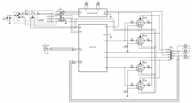
Your back-to-back diodes are commonly used to tie circuit common to chassis, in an attempt to reduce ground loops. The way you have your diodes arranged breaks code. The third prong of the power inlet should bond directly to chassis with no intentional impedance. Relocate those diodes to go between chassis and circuit common.
Your back-to-back diodes are commonly used to tie circuit common to chassis, in an attempt to reduce ground loops. The way you have your diodes arranged breaks code. The third prong of the power inlet should bond directly to chassis with no intentional impedance. Relocate those diodes to go between chassis and circuit common.
I just received the PCB's and I have completed acquiring all the oddball tubes to populate the driver PCB.
I am in the process of building a Mouser order for all the bits and bobs to go on the boards.
Then it's on to layout of the top plate since I'm planning on using 4 damper diodes instead of the SS rectifiers and I will use some Motor Run caps in the P/S also.
I have a feeling that these will be HUGE.
14"x21" maybe, so I will definitely need to order more .125" Aluminum and more Tiger Maple for the chassis'.
- Status
- This old topic is closed. If you want to reopen this topic, contact a moderator using the "Report Post" button.