After some first experiments with transconductance amplifiers for fullrange drivers and headphones I decided it was worth the effort to invest a bit more time in this topology.
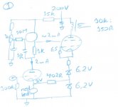
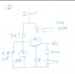
During the last weeks I built and tested some circuits. The one I liked most and therefore post at first is a screen driven 12W6GT. As driver I use a gyrator loaded 12SN7 (the MOSFET is a IRFBC30G). The 12SN7 is working at a rather low plate voltage, but I was encouraged by the operation point at low voltage I found elsewhere here at diyaudio (thanks Miles for posting them). Nevertheless I included two 6,2V zeners in series with the grid/cathode of the 12W6GT to allow a bit more voltage over the 12SN7 (and I could tap some current to feed into the cheap red led at the 12SN7’s cathode). Voltage at G2 is around 55V, current through 12W6 is about 45mA.
The choice for screen driven is because of the general opinion that screen driven generally has lower distortion than G1 driven pentode. It is also nice that the screen driven amplifier can be fed from a single voltage supply. The OPT is a 10k:150R from AE-Europe.
Possible improvements are the inclusion of a level shifter (maybe based on a TL431) between the gyrator source and the G2 screen, to drop some 20V – 30V to give even some more room to the driver tube. The inclusion of this level shifter allows more voltage at the driver tube’s plate and a swing at G2 closer to zero volts. I think this could be useful especially for bigger power amps (I am thinking about one with 6CB5 at the output to drive FR speakers).
I welcome any comment on how to improve this amp, keeping it a transconductance amp. I also welcome suggestions for other circuits of transconductance amps that I can try out.
One idea I am thinking is a cathode biased triode amp, and parallel to the bias resistor (or CCS) include a linear pot in series with a decoupling cap: turning the pot changes the plate impedance of the triode. What do you think?
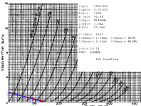
I am now working on measuring the performance of these amps (THD, etc).
During the last weeks I built and tested some circuits. The one I liked most and therefore post at first is a screen driven 12W6GT. As driver I use a gyrator loaded 12SN7 (the MOSFET is a IRFBC30G). The 12SN7 is working at a rather low plate voltage, but I was encouraged by the operation point at low voltage I found elsewhere here at diyaudio (thanks Miles for posting them). Nevertheless I included two 6,2V zeners in series with the grid/cathode of the 12W6GT to allow a bit more voltage over the 12SN7 (and I could tap some current to feed into the cheap red led at the 12SN7’s cathode). Voltage at G2 is around 55V, current through 12W6 is about 45mA.
The choice for screen driven is because of the general opinion that screen driven generally has lower distortion than G1 driven pentode. It is also nice that the screen driven amplifier can be fed from a single voltage supply. The OPT is a 10k:150R from AE-Europe.
Possible improvements are the inclusion of a level shifter (maybe based on a TL431) between the gyrator source and the G2 screen, to drop some 20V – 30V to give even some more room to the driver tube. The inclusion of this level shifter allows more voltage at the driver tube’s plate and a swing at G2 closer to zero volts. I think this could be useful especially for bigger power amps (I am thinking about one with 6CB5 at the output to drive FR speakers).
I welcome any comment on how to improve this amp, keeping it a transconductance amp. I also welcome suggestions for other circuits of transconductance amps that I can try out.
One idea I am thinking is a cathode biased triode amp, and parallel to the bias resistor (or CCS) include a linear pot in series with a decoupling cap: turning the pot changes the plate impedance of the triode. What do you think?
I am now working on measuring the performance of these amps (THD, etc).
Attachments
G1 driven pentode amp
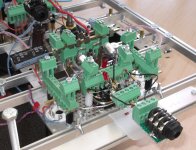
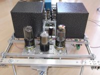
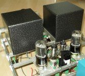
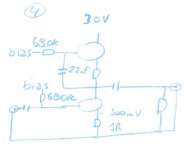
Second build is a G1 driven pentode amp with regulated (0B2) screens. Worked well, but didn’t sound as nice. I used the same output transformers, therefore both amps are on the same chassis.
edit: forgot to draw the input cap, but they are there!
Second build is a G1 driven pentode amp with regulated (0B2) screens. Worked well, but didn’t sound as nice. I used the same output transformers, therefore both amps are on the same chassis.
edit: forgot to draw the input cap, but they are there!
Attachments
Last edited:
") just kidding, and I'm envious of your name
just kidding, and I'm envious of your name As long as you are in the liniar area the slew rate is much higher than the usual way , at higher voltages, lower currents...punchy , powerfull , lots of highs that you don't usually get from valves , but the way they clip when outside that area....is so hard to some ears!About the highs...i'm not sure with that 90k anode load though...
Perhaps in that context it should be "pentoad"-based?There is Caged Frog, a pentode based transconductance amplifier for headphones.

Sorry, but I just can't resist a bad pun...
Pentoad vs. pendragon
Perhaps, but is pentoad any way lesser being than pendragon?
Perhaps in that context it should be "pentoad"-based?
Perhaps, but is pentoad any way lesser being than pendragon?
- Status
- This old topic is closed. If you want to reopen this topic, contact a moderator using the "Report Post" button.
- Home
- Amplifiers
- Tubes / Valves
- Transconductance amplifier for headphones.