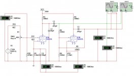
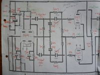
Here's a circuit I'm emulating and for the life of me I can't figure out how to adjust the gain of the second tube. I would think R9 would control the gain but that's also the grid resistor for the output tube. I would have to change R6 as well to keep the output tubes grids the same impedance.  But that puts me back where I started.
But that puts me back where I started.Attachments
The second valve should have a gain of 1, so no adjustment should be needed. You could separate the feedback function and grid leak function by using extra components..
2 more caps and 2 more resistors?
Bypassing R12 would help, by improving loop gain within the phase splitter.
That did help but still not completely symmetrical. At 20v out it's only 557mv difference between phases. That may be close enough.
I'm trying to design a PP amp with minimal components. I have a working paraphase circuit to within 20mv symmetry but the floating paraphase seems to be more forgiving in terms of values, tolerances, and component aging.
Last edited:
Here is a classic article (by Norman Crowhurst), how to balance floating paraphase.
The Floating Paraphase Circuit
The Floating Paraphase Circuit
Here is a classic article (by Norman Crowhurst), how to balance floating paraphase.
The Floating Paraphase Circuit
That schematic has what I was talking about with the output tube's grids having different value resistors. Not sure if that's a problem or not.
I'm not using fixed bias, yet.
Here's a circuit I'm emulating and for the life of me I can't figure out how to adjust the gain of the second tube
Don't worry about that. Get a better design, as this implementation of a Paraphase is more hideous than usual. The big problem with the whole paraphase family is unequal harmonic distortion. Making one half of it an anode follower will just make that problem that much worse.
If this is supposed to help generate even order harmonics to add tone to a guitar amp, there are better ways of accomplishing that.
Otherwise, an LTP with an active tail load will have much better balance, both AC and in terms of harmonic distortion. Uses fewer components as well.
Otherwise, an LTP with an active tail load will have much better balance, both AC and in terms of harmonic distortion. Uses fewer components as well.
Can you link an example?
It's for hifi use. I should also mention that I have 300vdc SMPS supply. Creating a negative voltage isn't that simple.
Last edited:
Can you link an example?
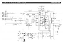
Two examples: Le Renard, Vixen (attached)
You could always make a negative rail from a small 24V PTX, like a control xfmr. That wouldn't be much of a problem if all you need is enough voltage for an active tail load.
Attachments
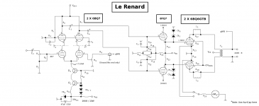
I tried the circuit at the bottom of this page The Valve Wizard -Long Tail Pair and it's garbage. Over 3v difference between phases. I don't think I've ever got anything off that site to work right. The ones you posted, I don't see how either of them use fewer components. The first would add 4 additional tubes, the second would add 3 (if they were all dual triodes). Due to the reason explained below, I need to use at little tubes as possible.
This is for a battery powered project using a 12vdc to 300vdc SMPS.
This is for a battery powered project using a 12vdc to 300vdc SMPS.
Last edited:
lazzer408....... "Over 3v difference between phases".
Study the documentation of amp circuits using that configuration; it will state that the anode resistor in the last section needs to be increased to correct the AC voltage symmetry.
In any case Amps which have such phasesplitter voltage discrepancy can also boast very low levels of distortion, as using global nfb does a wonderful job in correcting the error, also the varying gm of the output tubes. My 5-20 copy had exactly that unsymmetrical problem and as I get 0,05% thd !
richy
Last edited:
Two examples: Le Renard, Vixen (attached)
Really Miles, those are not appropriate suggestions for the OP's level of expertise. Stop showing off.
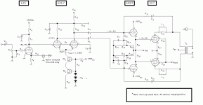
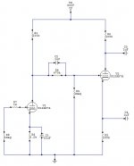
Lazzer, your main problem is the 330k grid leak you have attached to the phase inverting tube. You dont need it. See attached.
Attachments
What's that 68p doing ? 12AX series triodes don't need it.
Try this pic of the see-saw used in the 1955 GEC 88-50. Works a treat. Notice no commonmode ground for the 2nd triode half, instead taken through the 4M7 high pass into the proceeding stage brid leaks. This is an excellent solution.
I made several 3 stage 100W amps using this config.
richy
Try this pic of the see-saw used in the 1955 GEC 88-50. Works a treat. Notice no commonmode ground for the 2nd triode half, instead taken through the 4M7 high pass into the proceeding stage brid leaks. This is an excellent solution.
I made several 3 stage 100W amps using this config.
richy
Attachments
Lazzer, your main problem is the 330k grid leak you have attached to the phase inverting tube. You dont need it. See attached.
I have the experience to build anything but fairly new to the world of tubes. The design needs to be simple for other reasons, not my abilities.
I've seen that common grid leak resistor to ground used in many retail amps. What problem does it cause vs. using separate resistors?
What's that 68p doing ? 12AX series triodes don't need it.
Try this pic of the see-saw used in the 1955 GEC 88-50. Works a treat. Notice no commonmode ground for the 2nd triode half, instead taken through the 4M7 high pass into the proceeding stage brid leaks. This is an excellent solution.
I made several 3 stage 100W amps using this config.
richy
The 68p was for HF/RF suppression. Maybe better to place it on the input.
Your circuit seems to be close to what merlinb is suggesting but has additional coupling capacitors. I assuming that schematic has a fixed bias output stage?
EDIT - Oh I see those are driver tubes not output tubes. A little EQ'ing going on there?
What I'm after is a symmetrical PI (for hi-fi use) that can provide enough gain to drive a pair of 6BQ5, 6V6, or even 6L6 outputs. The floating paraphase seems like the best solution for my application. It takes the least amount of fine tuning and may be more stable over time from what I'm seeing. I'm also seeing less then perfect symmetry but as Richy pointed out, it may not be as important as I'm making it out to be.
Last edited:
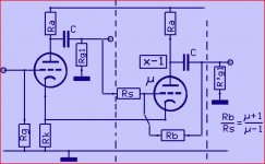
The parafase is simply a minus 1 amp.
If the gain of triode is infinit Rs=Rb ,but it is not ,hence the formula.
The current in one triode goes up (or down) the same amount as in the other one goes down (or up) ,so the voltage on the cathode resistor doesn't change,no need for a decoupling C.
It not really the µ that counts,it's the gain of the stage without the feedback,but a useble appoximation.
Mona
If the gain of triode is infinit Rs=Rb ,but it is not
,hence the formula.The current in one triode goes up (or down) the same amount as in the other one goes down (or up) ,so the voltage on the cathode resistor doesn't change,no need for a decoupling C.
It not really the µ that counts,it's the gain of the stage without the feedback,but a useble appoximation.
Mona
Attachments
Last edited:
- Status
- This old topic is closed. If you want to reopen this topic, contact a moderator using the "Report Post" button.
- Home
- Amplifiers
- Tubes / Valves
- Floating Paraphase.