New OTL headphone project with 6SN7 and 6AS7
Hi,
After two nice builds from PCB boards of Pete Millett I wanted to start a new project, this time with a PCB board by myself. After many boards with all digital schematics (another part of the hobby) with lot's of small pcb traces I wanted to work on something else and here it is:
I found a very nice shematic here
It is called "6as7 mini OTL" on the website, and the author has links to the schematics of the power section and on the amp.
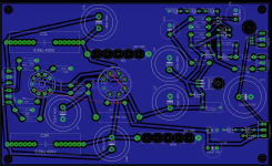
Based on those I am about creating a PCB board with the dimensions of 230X140mm which will also be the dimensions of the top plate of that amp.
The looks will be similar to the bottlehead crack amp, wood panels and a top plate with just 2 tubes and the transformer (in my case a toroidal one)
the two tube sockets will be soldered to the bottom layer, all other components will be placed on top. I almost managed to creat a one-layer board, there is one jumper wire plus the connection to the heater of the ec88 tube where I do not know if I should try to route it, or just sold a twister pair of cables...
As you see is that for the first time I did not route everything 45 and 90° which is really new to me.
It would be very nice to have some feedbacks, especially about my routing. I put all parts for the power supply on the right half, and all signals on the left side... but as mentioned, all pcb's I did were digital circuits")
So any comment/help is warmly welcomed.
By the way the transfomer is already in production (a toroidal one), and I already have a very nice top plate in prepreg carbon. The side panels of the amp will be made out of wood.
Attached there is an actual image of the pcb board and the schematics, plus the two eagle files.
Best regards
Chris
Hi,
After two nice builds from PCB boards of Pete Millett I wanted to start a new project, this time with a PCB board by myself. After many boards with all digital schematics (another part of the hobby) with lot's of small pcb traces I wanted to work on something else and here it is:
I found a very nice shematic here
It is called "6as7 mini OTL" on the website, and the author has links to the schematics of the power section and on the amp.
Based on those I am about creating a PCB board with the dimensions of 230X140mm which will also be the dimensions of the top plate of that amp.
The looks will be similar to the bottlehead crack amp, wood panels and a top plate with just 2 tubes and the transformer (in my case a toroidal one)
the two tube sockets will be soldered to the bottom layer, all other components will be placed on top. I almost managed to creat a one-layer board, there is one jumper wire plus the connection to the heater of the ec88 tube where I do not know if I should try to route it, or just sold a twister pair of cables...
As you see is that for the first time I did not route everything 45 and 90° which is really new to me.
It would be very nice to have some feedbacks, especially about my routing. I put all parts for the power supply on the right half, and all signals on the left side... but as mentioned, all pcb's I did were digital circuits
So any comment/help is warmly welcomed.
By the way the transfomer is already in production (a toroidal one), and I already have a very nice top plate in prepreg carbon. The side panels of the amp will be made out of wood.
Attached there is an actual image of the pcb board and the schematics, plus the two eagle files.
Best regards
Chris
Attachments
Last edited:
Hi,
A few quick thoughts:
- I don't like a ground plane with tubes. You have to think where the current loops are, and try to separate them (no common impedances) and close these loops as short as you can at the local reservoir capacitor.
- you should be aware that this amp works better with high impedance headphones. If your cans are 32 ohm, you made a bad choice.
- if you use high impedance headphones, you can (and should) replace the output caps with good quality film or film/oil, 47µ is enough for 300 ohms. Yes, the difference is quite big.
- 33R grid stopper is probably too small
- it sounds better when the left and right channels are decoupled (each channel with its own R-C power supply).
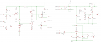
Ok project seems based on this : A Single-Ended OTL Amplifier for Dynamic Headphones | HeadWize
Anyway looking at the schamtic i was feeling something strange until i discovered MPSA92 to be a PNP and not a NPN as you drawn.
You're missing a resistor (10K) across outputs, i would go lower (say 1k), you need to be sure not to have DC on outputs at power on, introducing a antibump would be better for your headphones...
Also 1M as input is quite high and R2 (plate load for ECC88) must be 10 times higher, your scheme show 4.7K instead of 47K.
This is what i found to be wrong, but i don't have the time to look for each component, so be carefull and double check each component.
Also i'm a bit concerned with the 3.3K as cathode resistor for 6AS7...seems a bit high..
This schematic is in fact floating around the net for many, many years now...
I considered building it 10 years ago. But only because it was on the internet in the nice write up by Van der Waarde doesn't mean it is a good schematic.
When building a 6AS7G based headphone amplifier I would definitely consider the schematic of the HA-2 by Pete Millet. This one differs quite a bit but seems to be thought out much better and was even produced commercially back in the days. Hope no one will object when I am posting the schematic again...
I also had a go at the schematic myself years back and came up with a different CCS-loaded driver... feel free to take it apart!
PS: I'll second Vincent in that OTL amps are for high impedance headphones only... no matter what people claim.
And like he says... use smaller and good caps for the output... who wants to pass the precious audio signal through big
honking electrolytic caps?
Attachments
Last edited:
Hi
Yes the heatsink planned has to be big and will be on the outside of the enclosure. I am aware of this thanks.
Why etch a PCB ? I like PCB's and have not really a lot of experience in point-to-point wiring. And at the moment I have plenty of time in the office
Thanks as well for the pmillett schematics. I should have asked before, as the transfomer is already in production (secondary1: 115-0-115, secondary2: 9-0-9.
And I really like the design with the 2 tubes, especially the 6080 tubes.
So I guess I will (have to) stick with this design, and correct the errors as I don't want to throw away the 60 Euro transformer and the nice Svetlana Tube
Keeping you updated tomorrow about the changes:
- The plate load resistors were an error, put them to 47k
- Output capacitor changed to 47uF (have to look for 47uF film caps)
- What to take as grid stopper instead of 33R ?
- What to take for input instead of 1M ?
Thanks again all Appreciate your help
Christoph
Yes the heatsink planned has to be big and will be on the outside of the enclosure. I am aware of this thanks.
Why etch a PCB ? I like PCB's and have not really a lot of experience in point-to-point wiring. And at the moment I have plenty of time in the office
Thanks as well for the pmillett schematics. I should have asked before, as the transfomer is already in production (secondary1: 115-0-115, secondary2: 9-0-9.
And I really like the design with the 2 tubes, especially the 6080 tubes.
So I guess I will (have to) stick with this design, and correct the errors
as I don't want to throw away the 60 Euro transformer and the nice Svetlana Tube Keeping you updated tomorrow about the changes:
- The plate load resistors were an error, put them to 47k
- Output capacitor changed to 47uF (have to look for 47uF film caps)
- What to take as grid stopper instead of 33R ?
- What to take for input instead of 1M ?
Thanks again all
Appreciate your helpChristoph
Last edited:
I'm agree. I made the same amplifier.Hi,
A few quick thoughts:
- I don't like a ground plane with tubes. You have to think where the current loops are, and try to separate them (no common impedances) and close these loops as short as you can at the local reservoir capacitor.
- you should be aware that this amp works better with high impedance headphones. If your cans are 32 ohm, you made a bad choice.
- if you use high impedance headphones, you can (and should) replace the output caps with good quality film or film/oil, 47µ is enough for 300 ohms. Yes, the difference is quite big.
- 33R grid stopper is probably too small
- it sounds better when the left and right channels are decoupled (each channel with its own R-C power supply).
1.Using two caps with different structure is not good idea for output signal, crossing two different media and will make the sound some blurred for HF. I use Siemens 47 uF.
And the same for cathode caps. You can use only big cap, like ELNA Cer., Black gate, Panasonic, Rubycon.
2.If amplifier works good in low and high volume without input signal and without oscillations, You don't need 33 ohm. But if You want put it, try with 500 ohm - 1 kohm.
3.IMO, using CCS in plate will good for mode, but will decrease dynamic.
4.After tube rect. You can make two filter channels.
Last edited:
I also agree that the 6AS7G "Waarde amp" is not so good with 32R headphones. I only had Grados when I built the amp and the bass was not good with them. It's better with higher impedance phones. Maybe you just need to build one and test how you like it.
I didn't calculate how much the another schema's amp would draw but if your 115-0-115V transformer is big enough (let's say the total draw is max 200mA) you should get B+ between 290-300V if you use it as 0-230V trafo in a C-L(or R)-C power supply. Don't change the tube yet I like the 6AS7G also. If you need to change something change the transformer and use the it with your next project. You'll need a pre amp also
I didn't calculate how much the another schema's amp would draw but if your 115-0-115V transformer is big enough (let's say the total draw is max 200mA) you should get B+ between 290-300V if you use it as 0-230V trafo in a C-L(or R)-C power supply. Don't change the tube yet
I like the 6AS7G also. If you need to change something change the transformer and use the it with your next project. You'll need a pre amp also Hi,
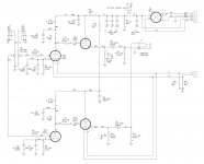
This circuit whilst adding another 6AS7 should do a much better job at driving cans, any can really.
SRPP input stage followed by a WCF output. Z out should be well below 8 ohm.
You can even do away with the bypass cap of the bottom half of the WCF it's only degrading the sound.
There's probably no need for grid stoppers either, they'll only add noise.
An individual, well smoothed (choke?) PS per channel would be nice too....
Another little trick, insert a 220R (10W? didn't do the math)) resistor between plate and cathode of the 6AS7 WCF and take the output from the bottom triode's plate.
PP SE... or almost.
Last trick, 6AS7 and consorts being dual triodes and not twin triodes (not that any current manufacture twin triodes exist but still) they rarely come with matched triode halves (with the exception being the WE 421 but I digress). You then either want to select from a bunch and find out you need at least 50 of them to come close or you buy some 1/2 6AS7s like EC360 (close) or 6S19S (also close) or the real one called A2293 or an American made equivalent which number I don't know by heart (7233 or something like that).
The latter opton makes selection much easier as you can easily build close enough sets.
IMHO a simple SE output xformer with output tabs up to 600R should sound better than a large film cap. But then you can't possibly call it an OTL amp....
Ciao,
EDIT: BTW: the topic title is misleading: the circuit uses a ECC88 and not a EC88 (which also exists). Do you mind correcting it? Thx.
This circuit whilst adding another 6AS7 should do a much better job at driving cans, any can really.
An externally hosted image should be here but it was not working when we last tested it.
SRPP input stage followed by a WCF output. Z out should be well below 8 ohm.
You can even do away with the bypass cap of the bottom half of the WCF it's only degrading the sound.
There's probably no need for grid stoppers either, they'll only add noise.
An individual, well smoothed (choke?) PS per channel would be nice too....
Another little trick, insert a 220R (10W? didn't do the math)) resistor between plate and cathode of the 6AS7 WCF and take the output from the bottom triode's plate.
PP SE... or almost.
Last trick, 6AS7 and consorts being dual triodes and not twin triodes (not that any current manufacture twin triodes exist but still) they rarely come with matched triode halves (with the exception being the WE 421 but I digress). You then either want to select from a bunch and find out you need at least 50 of them to come close or you buy some 1/2 6AS7s like EC360 (close) or 6S19S (also close) or the real one called A2293 or an American made equivalent which number I don't know by heart (7233 or something like that).
The latter opton makes selection much easier as you can easily build close enough sets.
IMHO a simple SE output xformer with output tabs up to 600R should sound better than a large film cap. But then you can't possibly call it an OTL amp....
Ciao,
EDIT: BTW: the topic title is misleading: the circuit uses a ECC88 and not a EC88 (which also exists). Do you mind correcting it? Thx.
Last edited:
moving on to frank's design ?
Hi guys. I don't use low impedance cans normally, but I have some like 32R Sennheisers for the office and among my cans are also Grado's. So it is clear it would be nice to use any of them but it does not really matter.
Anyway, thanks for all your comments, appreciate it
Frank: Thanks a lot for your comments and the schematics. I am really tented to abandon the actual schematics and use yours with 4 tubes. And I could use what I already bought.
(I have already the James transformers for the next winter project which will be a SE amp so why not SRPP for the headphone amp )
Best regards
Christoph
Hi guys. I don't use low impedance cans normally, but I have some
like 32R Sennheisers for the office and among my cans are also Grado's. So it is clear it would be nice to use any of them but it does not really matter.Anyway, thanks for all your comments, appreciate it
Frank: Thanks a lot for your comments and the schematics. I am really tented to abandon the actual schematics and use yours with 4 tubes. And I could use what I already bought.
(I have already the James transformers for the next winter project which will be a SE amp so why not SRPP for the headphone amp
)Best regards
Christoph
If you want to go that way, Broskie has an article on White Cathode Follower using 6AS7G: Aikido Push-Pull
Thanks Vincent.
After all the comments I got I think it is worth to go that way. And I can keep the parts I already have (expensive prepreg carbon top plate, cnc milled side panels, part of the tubes and not to forget the tranny which is in production in Germany.
And I can also use my low impedace cans (I have low Z and high Z ones).
Which means I can use the amp in my office as well with my new Sennheisers cool.
Thanks for all the inputs as I am no tube guru at all. I know how to make PCB's (until now just digital circuits), how to make CNC CAD files, solder, assembly, troubleshooting etc. but I don't really have the competence do design / modify schematics :-(
Best regards
Christoph
After all the comments I got I think it is worth to go that way. And I can keep the parts I already have (expensive prepreg carbon top plate, cnc milled side panels, part of the tubes
and not to forget the tranny which is in production in Germany.And I can also use my low impedace cans
(I have low Z and high Z ones).Which means I can use the amp in my office as well with my new Sennheisers
cool.Thanks for all the inputs as I am no tube guru at all. I know how to make PCB's (until now just digital circuits), how to make CNC CAD files, solder, assembly, troubleshooting etc. but I don't really have the competence do design / modify schematics :-(
Best regards
Christoph
Last edited:
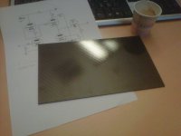
"top plate"
Vincent, I made a picture with what I mean with top plate...
Just wanted to say that I would not like to change the dimensions of the future case
Sooooo. After Frank's input I will add to tubes and change the schematics, plus as I am good listener (with 51 years hehehe), I will abandon the PCB board for the amplifier part and try point-to-point wiring.
Any suggestions for the power supply ? Is the one I put to the first post OK ?
Regards
Christoph
Attachments
The PSU is good, but I recommend a resistor in the voltage reference instead of the diodes, because the Zeners drift when they get hot and are noisy.
The main problem is the heating - 5A DC from a linear regulator means A LOT of wasted heat.
So, you either use AC for the two 6AS7G , and with careful wiring, layout and referencing you won't get any hum, or you buy a switching mode PSU for the heaters, which doesn't need a transformer and does not get very hot. I will send you links if you want.
Edit: I have just notriced a wrong value in the PSU schematic - R14 should be 100K, not 560R.
Last edited:
Hi,
Heaters can be A.C., easier and with care should be hum free.
For B+ I'd like a tube rectifier (a nice coke bottle style octal one) followed by a smoothing choke(s) and dome RC filtering, good low esr caps (could be polyprops since we're not above 200VDC.
This will also allow some delay for the 6AS7's to warm up. They do not like to be brutalised.
One PSU per channel if possible and ideally the heater supply not on the same power xformer as the B+
Static shields and low stray fields are of course welcome.
We'll make a nice dashboard out of that sheet of carbon later on.....
Ciao,
EDIT: If you really want to get fancy then the 6J5G (not the 6J5 which is a metal tube) is half a 6SN7. The reason I mention this is that these are still not too expensive whereas a half decent 6SN costs an arm and a leg nowadays. Unlike most of the 12V novals you can't wire a 12SN7 for 6V heating.
Last edited:
Hi,
A few quick thoughts:
- I don't like a ground plane with tubes. You have to think where the current loops are, and try to separate them (no common impedances) and close these loops as short as you can at the local reservoir capacitor.
- you should be aware that this amp works better with high impedance headphones. If your cans are 32 ohm, you made a bad choice.
- if you use high impedance headphones, you can (and should) replace the output caps with good quality film or film/oil, 47µ is enough for 300 ohms. Yes, the difference is quite big.
- 33R grid stopper is probably too small
- it sounds better when the left and right channels are decoupled (each channel with its own R-C power supply).
Ground planes are not as bad as you think, I've done several projects, both preamps and power amps with ground planes, and haven't had any issues. It may just depend on the design, not sure.
The tranny I ordered is calculated for 50VA on the heater side, which means by doubling the tubes I am on the limit. the big tubes will pull 2.5A, the small ones if I understood correctly 300mA. So another tranny or a switched psu - will see.
Thanks for sending me the links.
Thanks for sending me the links.
Ground planes are not as bad as you think, I've done several projects, both preamps and power amps with ground planes, and haven't had any issues. It may just depend on the design, not sure.
Thanks Denny for the input. During lunch I had time for some reflections and decided to give both point-to-point and pcb a try, then compare. And measure.
Being an engineer (network, not electronics), this will leave no place for guesswork.
The good things about PCBs is that I can do them during work
, assembly not.- Status
- This old topic is closed. If you want to reopen this topic, contact a moderator using the "Report Post" button.
- Home
- Amplifiers
- Tubes / Valves
- New OTL headphone project with EC88 and 6080