Shorting or Non-Shorting Rotary Switch: Hi-Low Z tube headphone amp
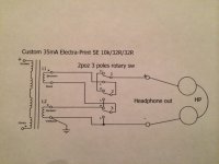
I am in progress of building a tube headphone amp. I am using a custom Electra-Print OT that has two 32 ohms secondary windings. I plan to use a 2 position 3 poles rotary switch.
Dilemma is which kind of switch, shorting or non-shorting:
• shorting ("make before break") means momentarily short position H and L when rotate. In this case during the action of rotation both secondary windings are short-circuited and therefore the final tube sees a Zero ohms load.
• non-shorting ("break before make") means that connection is broken for the moment of rotation. In this case, during the action of rotation, both secondary windings are disconnected from output and therefore the final tube sees infinite load.
Now the question is : "what is less destructive: short circuit or open circuit?". I would like to make this amp idiot proof and not to worry that I am going to destroy the OT or prematurely wear out the final tube. Or I should not worry at all considering that the action of switching is more likely less than 1 second.
Anybody out there who encountered this issue ?
Picture below showing the connections of the switch. "H" is for high Z( 128ohm) and "L" is for low Z (32ohm).
Best,
Radu
Attachments
Radu,
You have analysed the problem nicely and reduced it to "what is the best between a momentarily shorted output (make before break) and a momentary open circuit (break before make) output during switching".
Can you tell us what is on the primary side of the transformer?
We could then make more informed advise.
Without seeing that I would GUESS that break before make (momentary open circuit) would be the better choice as that "open circuit" can be managed by permanently wired "minimum" load of say 470 Ohms across each 32 Ohm winding.
Cheers,
Ian
Last edited:
Hi Ian,Radu,
You have analysed the problem nicely and reduced it to "what is the best between a momentarily shorted output (make before break) and a momentary open circuit (break before make) output during switching".
Can you tell us what is on the primary side of the transformer?
We could then make more informed advise.
Without seeing that I would GUESS that break before make (momentary open circuit) would be the better choice as that "open circuit" can be managed by permanently wired "minimum" load of say 470 Ohms across each 32 Ohm winding.
Cheers,
Ian
Sorry I was not clear enough.
This is tube amp using 4P1L triode strapped at 250V, 35 mA,-21V filament bias.
I am not as much concerned about the tube as I am about the transformer. The OT is 30 times more expensive than the tube.
Also having additional resistors connected parallel across the secondary will probably change the sound. I am just guessing.
Thanks,
Radu
Interesting thread. I am also building a tube headphone amp with output transformer. I am putting locking 1/4" stereo headphone jacks so that it can't come unplugged and un-load the transformer while it is powered up. I am also putting a standby switch labled somthink like "Change Headphones" so it means put it in standby before changing headphones.
Last edited:
Interesting thread. I am also building a tube headphone amp with output transformer. I am putting locking 1/4" stereo headphone jacks so that it can't come unplugged and un-load the transformer while it is powered up. I am also putting a standby switch labled somthink like "Change Headphones" so it means put it in standby before changing headphones.
I like the idea of having a locking jack. I was thinking of having that standby switch. However, I want it simple, too many switches can create confusion.. But thanks for the idea.
Based on the fact that many Guitar Amplifiers have shorting output jacks, I would suggest the make-before-break switch.
Tubes driving output transformers tolerate momentary shorts better than they handle discontinuities in the output load.
Totaly agree with you. Don't want to have any transients and high voltage spikes in the OT.
I was also thinking of having a mute switch instead of having to turn the volume down every time i need to switch. I want to be able to mute the input signal before switching.
I don't recall that the headphone tube amps on the market have switching safety features.
I know in some designs there is a resistor placed in parallel with the secondary winding. In that case I can break before make switch.
I hope that I am not over analyzing this....
Thanks,
Radu
• shorting ("make before break") means momentarily short position H and L when rotate. In this case during the action of rotation both secondary windings are short-circuited and therefore the final tube sees a Zero ohms load.
• non-shorting ("break before make") means that connection is broken for the moment of rotation. In this case, during the action of rotation, both secondary windings are disconnected from output and therefore the final tube sees infinite load.
None of the two is correct. Those are only true for an ideal transformer.
A real transformer has a DC resistance, finite inductance, leakage and core losses that set limits in any case.
It is rather an transient issue.
None of the two is correct. Those are only true for an ideal transformer.
A real transformer has a DC resistance, finite inductance, leakage and core losses that set limits in any case.
It is rather an transient issue.
45,
Are you saying that I should not worry, and choose the shorting one?
45,
Are you saying that I should not worry, and choose the shorting one?
No I was not saying this.
I wouldn't choose it without that fixed resistor in parallel. I have never tried but I guess that if you have DC current + signal and short the secondary long enough without that resistor you might damage the insulation because all the power will be dissipated in the transformer. For how long you can short it without causing damage depends of course on the transformer specs as well. That resistor in parallel helps and in such case I think the transformer has no special requirements to fulfill.
Last edited:
No I was not saying this.
I wouldn't choose it without that fixed resistor in parallel. I have never tried but I guess that if you have DC current + signal and short the secondary long enough without that resistor you might damage the insulation because all the power will be dissipated in the transformer. For how long you can short it without causing damage depends of course on the transformer specs as well. That resistor in parallel helps and in such case I think the transformer has no special requirements to fulfill.
Thank you for making things clear. Yes, fixed resistor in parallel and non-shorting would be the safest choice. Just not sure what value should be the resistor so it wont impact sound quality, timbre. I will definetely experiment.
I have a single ended all DHT amp delivering on 8 ohms speakers. I installed a headphone jack and tried with and without resistor in parallel. The sound was significantly better without resistor. Headphone used were 50ohm Sennheiser HD595. But this was 50 ohm load on 8ohm output, and caused the primary of the OT to jump from 3K to 3x6=18K, reducing THD.
In the case of 32ohm load on 32 ohm output, using a let say 330 ohm, parallel resistor will reduce the load to about 29 ohm and most likely slightly increase THD. Not sure if it will make a noticable difference in sound.
For audio signals you always want a shorting (make before break) switch. I use Grayhill 53 series rotory switches that have 24 positions.
Can you elaborate? Are you reffering to small signals?
Thanks
Surely resistive loading will change the sound. Resistive loading has much less impact when power transfer is not so important. Generally I don't like the volume control at the output, even for a line preamp.
45,
Not easy to decide. There is always a compromise..😁
I migh just buy both type and experiment. It would be nice to have the tools to measure transients.
In case I want to switch from high to low while having same headphones connected, then shorting would make more sense. ( in case I forget to mute before switch🙉
Radu
Can you elaborate? Are you reffering to small signals?
Thanks
Yes, small signal. I would not recommend switching anything with power (power signal) on it without first turning it off. It is hard on the contact surfaces.
Hi Radu,
I would not wish to take any risks with an expensive transformer, nor to spoil it with dummy-loads (needed only for switching). So it seems to me that neither Shorting- nor NonShorting will be satisfactory.
Instead, we could render the Transformer safe, by de-energising it before switching.
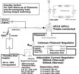
A simple way to do that might be to make a "Grid-Bias Standby Switch":
- it pulls the tube grid with enough negative voltage to cut-off the anode current.
This facility would also allow safe warm-up of the filaments, even when you have SS or directly-heated rectifiers.
With the standby-bias active, the trafo has zero stored-energy, so it is safe to switch with open or shorted secondary-windings.
The bias voltage is right out of the circuit when the amp is running, and has no load. This means that it does not require careful filtering - and cheap small caps can be used. A voltage doubler (2 diodes, 2 caps) and a spare power trafo winding of 12V to 30V should work for most purposes.
I would not wish to take any risks with an expensive transformer, nor to spoil it with dummy-loads (needed only for switching). So it seems to me that neither Shorting- nor NonShorting will be satisfactory.
Instead, we could render the Transformer safe, by de-energising it before switching.
A simple way to do that might be to make a "Grid-Bias Standby Switch":
- it pulls the tube grid with enough negative voltage to cut-off the anode current.
This facility would also allow safe warm-up of the filaments, even when you have SS or directly-heated rectifiers.
With the standby-bias active, the trafo has zero stored-energy, so it is safe to switch with open or shorted secondary-windings.
The bias voltage is right out of the circuit when the amp is running, and has no load. This means that it does not require careful filtering - and cheap small caps can be used. A voltage doubler (2 diodes, 2 caps) and a spare power trafo winding of 12V to 30V should work for most purposes.
Attachments
Rod,Hi Radu,
I would not wish to take any risks with an expensive transformer, nor to spoil it with dummy-loads (needed only for switching). So it seems to me that neither Shorting- nor NonShorting will be satisfactory.
Instead, we could render the Transformer safe, by de-energising it before switching.
A simple way to do that might be to make a "Grid-Bias Standby Switch":
- it pulls the tube grid with enough negative voltage to cut-off the anode current.
This facility would also allow safe warm-up of the filaments, even when you have SS or directly-heated rectifiers.
With the standby-bias active, the trafo has zero stored-energy, so it is safe to switch with open or shorted secondary-windings.
The bias voltage is right out of the circuit when the amp is running, and has no load. This means that it does not require careful filtering - and cheap small caps can be used. A voltage doubler (2 diodes, 2 caps) and a spare power trafo winding of 12V to 30V should work for most purposes.
This is a great idea. My wories are gone. What a simple and effective solution.
I was so stuck on the switch and how to make it work without additional devices, that the obvious was not obvious anymore. However, if the B+ is not stabilized it will raise by RDcr total x 2xIplate ( this could be somewhere from 5V to 50V depending on the supply design.
Thank you,
Radu
Last edited:
- Status
- This old topic is closed. If you want to reopen this topic, contact a moderator using the "Report Post" button.
- Home
- Amplifiers
- Tubes / Valves
- Shorting or Non-Shorting Rotary Switch: Hi-Low Z tube headphone amp