Caused by some agressive advertisement around the KT150 ("up to 300W out of a pair in PP") I have made a quick evaluation of that tube and compared it with the KT120.
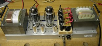
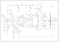
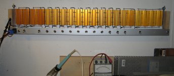
I have used may PP powerstage bench - picture and schematic below - able to drive AB1 and AB2. The OT (250W, 20Hz-20KHz , - 3db points) has Raa=4K and speaker output of 4 and 8 Ohm. Using the 4 OHm connection and a switchable high power load in steps of 0,5 Ohm - picture below - I am able to measure the max power before clipping starting e.g with Raa=3K up to Raa=8K in steps of 0,5K.
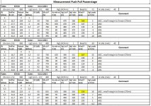
I have put the results into 3 tables: KT150,KT120 and the difference between the results.
Some remarks and explanations:
- The evaluation bench is not a state of the art design It is for evaluation purpose only and without protection elements inside.
As an example you can easily evaporate G1 if you want ...
- Ub connection: "nominal Voltage" at OT, in Idle higher , at full power lower due to SAG
- Ug2 connection: "nominal Voltage" at supply of Rg2, in Idle higher, at full power lower due to SAG
- screen resistor 1K separate for each tube
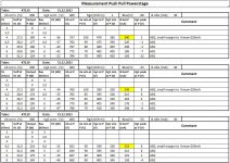
These topics have been measured at 500Hz
- output voltage at full power before clipping
- K3: signal Ratio of K3 (1500Hz) to K1 (500Hz) at full power
- Ub at full power
- Ua min: lowest plate voltage during sinus cycle at full power
- Ug2 at full power
- Ug2 min: lowest screen voltage during sinus cycle at full power
- Ik: average cathode current of one tube at full power
- Ug1 peak: the highest voltage at the control grid at full power
My observations up to now:
- from my experience a maximum power of 300W out of KT150 PP seems not to be reachable. 220W looks "ok". With an OT having very low DC resistance at the primary up to 250W might be reachable but without any margin.
- the difference between KT150 and KT120 is small which I have somewhat expected: same manufacturer, the tube is just a little bit "extended". The shown difference might even come from the variation in production.
- Due to the higher limit of Ik (275mA versus 250mA) for the KT150 2 more configs with higher output power are possible.
- the warm up time of the tube is about 2 min - very long compared to e.g. GU50
Thats all for the moment.
Hans- Georg
I have used may PP powerstage bench - picture and schematic below - able to drive AB1 and AB2. The OT (250W, 20Hz-20KHz , - 3db points) has Raa=4K and speaker output of 4 and 8 Ohm. Using the 4 OHm connection and a switchable high power load in steps of 0,5 Ohm - picture below - I am able to measure the max power before clipping starting e.g with Raa=3K up to Raa=8K in steps of 0,5K.
I have put the results into 3 tables: KT150,KT120 and the difference between the results.
Some remarks and explanations:
- The evaluation bench is not a state of the art design It is for evaluation purpose only and without protection elements inside.
As an example you can easily evaporate G1 if you want ...
- Ub connection: "nominal Voltage" at OT, in Idle higher , at full power lower due to SAG
- Ug2 connection: "nominal Voltage" at supply of Rg2, in Idle higher, at full power lower due to SAG
- screen resistor 1K separate for each tube
These topics have been measured at 500Hz
- output voltage at full power before clipping
- K3: signal Ratio of K3 (1500Hz) to K1 (500Hz) at full power
- Ub at full power
- Ua min: lowest plate voltage during sinus cycle at full power
- Ug2 at full power
- Ug2 min: lowest screen voltage during sinus cycle at full power
- Ik: average cathode current of one tube at full power
- Ug1 peak: the highest voltage at the control grid at full power
My observations up to now:
- from my experience a maximum power of 300W out of KT150 PP seems not to be reachable. 220W looks "ok". With an OT having very low DC resistance at the primary up to 250W might be reachable but without any margin.
- the difference between KT150 and KT120 is small which I have somewhat expected: same manufacturer, the tube is just a little bit "extended". The shown difference might even come from the variation in production.
- Due to the higher limit of Ik (275mA versus 250mA) for the KT150 2 more configs with higher output power are possible.
- the warm up time of the tube is about 2 min - very long compared to e.g. GU50
Thats all for the moment.
Hans- Georg
Attachments
-
 Powerstage KT150 PP picture 1 small.jpg517.8 KB · Views: 4,358
 -
 KT150 PP powerstage Rel 1.png22.9 KB · Views: 4,156
 -
 switchable load.jpg437.5 KB · Views: 4,046
 -
 Measurement results KT150.jpg185.1 KB · Views: 3,889
 -
 Measurement results KT120.jpg182.7 KB · Views: 3,710
 -
 Measurement results Delta KT150 - KT120.jpg182.8 KB · Views: 1,313
Interesting.
Love that resistor array. Wanted to build a similar thing, but in a R2R fashion, means a 1, 2, 4, 16, 32, 64, etc. resistor chain. You can constrcut any resistance with that.
The results are kind of predictable. Why ?
For max. output power you need Class-B. Heat inertia matters and not Pa-max in this case. The fact that music has a high crest-factor (thanks tubelab for this genious paraphrase (see here: http://www.diyaudio.com/forums/tubes-valves/110144-class-b-triodes.html)) means that you can get way more output Power than DC anode dissipation. What matters most is the max. anode voltage and cathode current. These are the limits for your class-B loadline. BUT KT150 and KT120 both only allow 850V on the Anode. Their Ik-max is only 25mA different. So in terms of max. allowable output, these are essentially the same tubes !!
It's a different story when we're talking about Class-A. Then you have 70/60 of the output Power, or about 17% more.
In my opinion, the KT150 is a nice tube for a fancy powerful Class-A amp (even as pseudotriode) when you don't want these nasty high voltage transmitting tubes. Or you don't want these nasty super high gm, unlinear, current regulation tubes as 6C33, etc.
The KT150 has just the right gm that you don't need a super dooper driver for either high voltage swing or on the other hand, huge current/capacity driving abilities.
It's just too expensive. You get can an EL156 in that price range.
Love that resistor array. Wanted to build a similar thing, but in a R2R fashion, means a 1, 2, 4, 16, 32, 64, etc. resistor chain. You can constrcut any resistance with that.
Basically a good idea. But: You'd need BCD switches that are able to handle rather high currents. Not easy to find, especially in these days.
Btw, thanks to es345 (Hans-Georg) for his informative and sophisticated work!
Best regards!
Caused by some agressive advertisement around the KT150 ("up to 300W out of a pair in PP") I have made a quick evaluation of that tube and compared it with the KT120....
Hans- Georg
A couple of observations. The screen grid resistor ( 1k ) seems to be too big if maximum output power is a goal. The voltage drop across it is noticeable.
The screen voltage should be quite constant. Some 100 ohms will give essentially better result.
Secondly, the max. specified screen voltage is 650 V, but you have used only 480 V. This will also limit the max. power a lot.
Secondly, the max. specified screen voltage is 650 V, but you have used only 480 V. This will also limit the max. power a lot.
The 650V g2 rating is likely just for the triode/UL operation.
Last edited:
Due to the higher limit of Ik (275mA versus 250mA) for the KT150 2 more configs with higher output power are possible.
the 6LF6. 6LW6, 6KG6/EL509 has Ik at 400 mA....i am more excited about the GU-50...

The 650V g2 rating is likely just for the triode/UL operation.
I have KT120 specifications. There max. G2 voltage is 650 V for pentode connection and 600 V for triode and UL.
Concerning the effect of the G2-resistor. I once tested a high power pentode connected PL519 circuit.
In the beginning I used 680 ohms G2-resistors. When I changed those to 47 ohms, the output power increased some 15 %.
Patrick Turner has an informative write up here: loadmatch5-beam-tetrodes-about
Patrick Turner has an informative write up here: loadmatch5-beam-tetrodes-about
A quote from the above link: " High power is always possible with very low anode loads if the screen voltage is raised to a highest possible voltage."
This presents well the meaning of the screen grid voltage vs. max. output power.
As a summary what I have tried to say:
The test above does not fully describe the full potential of KT150, because there seems to be such limiting factors as too high screen grid resistor and possibly too low screen grid voltage.
When those will be eliminated and new tests done, then we could have valid test results.
The test above does not fully describe the full potential of KT150, because there seems to be such limiting factors as too high screen grid resistor and possibly too low screen grid voltage.
When those will be eliminated and new tests done, then we could have valid test results.
Some explanations and comments.
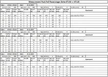
1. Dependency of the max output power from screen supply (g2)
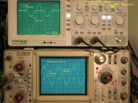
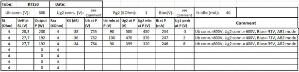
In the scope picture attached you can see the definition of Ua min and Ug2 min. In the table attached you can see the output power with a Ug2 connection of 600V, 480V and 400V. The reachable output power is nearly the same, but the operation mode is shifting from AB1 to AB2 mode. If you don't allow AB2 at lower G2 supply then the maximum output power will decrease with lower G2 supply.
2. Rg2 = 1 KOhm.
Let us have a short estimation, not precise from model and mathematics but from my opinion good enough to estimate the G2 power dissipation for the case shown in the scope picture: Ug2 at 600V connection.
During inactive phase of the tube G2 current is 0 therefore the voltage at G2 is the same as the G2 supply at the other side of Rg2. During the active phase the G2 voltage is following a curve like a sinus. The average voltage at the Rg2 resistor is (Ug supply- Ug2 min)/2, this is the midpoint of the sinus. In the excel attached I have calculated the average power dissipation for the screen G2 supplied with with 600V, 480V and 400V.
The result is that the 600V config is overloading G2 at full power (15,7W) - which fits to the observation that the inside of the tube the colour is changing to red.
1. Dependency of the max output power from screen supply (g2)
In the scope picture attached you can see the definition of Ua min and Ug2 min. In the table attached you can see the output power with a Ug2 connection of 600V, 480V and 400V. The reachable output power is nearly the same, but the operation mode is shifting from AB1 to AB2 mode. If you don't allow AB2 at lower G2 supply then the maximum output power will decrease with lower G2 supply.
2. Rg2 = 1 KOhm.
Let us have a short estimation, not precise from model and mathematics but from my opinion good enough to estimate the G2 power dissipation for the case shown in the scope picture: Ug2 at 600V connection.
During inactive phase of the tube G2 current is 0 therefore the voltage at G2 is the same as the G2 supply at the other side of Rg2. During the active phase the G2 voltage is following a curve like a sinus. The average voltage at the Rg2 resistor is (Ug supply- Ug2 min)/2, this is the midpoint of the sinus. In the excel attached I have calculated the average power dissipation for the screen G2 supplied with with 600V, 480V and 400V.
The result is that the 600V config is overloading G2 at full power (15,7W) - which fits to the observation that the inside of the tube the colour is changing to red.
Attachments
The overloading of G2 is possible/obvious when this kind of circuit is driven at absolute max. output power. However, I think this is not relevant, if we only want to determine how much power is possible to "get out" of a pair of KT150.
This is because such situation - full power with sine wave for long time - is not normal in case of Hifi-amplifiers.
Can you just replace 1k screen grid resistors with, say 100 ohms and make a short test ?
Have you studied what bias voltage gives best power/THD ?
This is because such situation - full power with sine wave for long time - is not normal in case of Hifi-amplifiers.
Can you just replace 1k screen grid resistors with, say 100 ohms and make a short test ?
Have you studied what bias voltage gives best power/THD ?
Ok, i will try a short test on Monday. I must be very fast: adjust the input level, make a picture and back to zero input:. At the end let us see what the remaining minimum plate voltage will be, that finally defines the output power. Regarding THD: I am able to measure single Kx values via a PC freeware program "audioanalyser"(poor mans solution up to know). If you know a better program, you are welcome.
Up to now you can see that K3 compared to K1 is going down with higher screen voltage (see table above)
Personally I am interested in the maximum stable continuous output power. For hifi applications 600V at the screen grid might work. In other applications like bass amps the situation is different.
. At the end let us see what the remaining minimum plate voltage will be, that finally defines the output power. Regarding THD: I am able to measure single Kx values via a PC freeware program "audioanalyser"(poor mans solution up to know). If you know a better program, you are welcome.Up to now you can see that K3 compared to K1 is going down with higher screen voltage (see table above)
Personally I am interested in the maximum stable continuous output power. For hifi applications 600V at the screen grid might work. In other applications like bass amps the situation is different.
Last edited:
- Status
- This old topic is closed. If you want to reopen this topic, contact a moderator using the "Report Post" button.
- Home
- Amplifiers
- Tubes / Valves
- Comparison KT150 versus KT120