Are 3c24's a bad idea for a preamp? I see 3c24's are often used as a drivers.
I was playing w/ one last night, and know it will function, but I suppose I could say that of any tube... I'm basically wondering if it's worth going down this path, or if I should stop before I waste my time. These are odd tubes, and the consequences of that are still over my head.
I've got the tubes and filament regulators for them already, for a project I decided not to build.
Overkill for sure but sure hey why not if you really want to. This one Japanese site had lots of amps based on transmitting tubes and their 3c24 designed looked good. Although after looking at their distortion figures it looked pretty bad after 2-3 watts, like 8-10%.
Pay close attention to the operating points. You want the plate to be red but not orange.
Pay close attention to the operating points. You want the plate to be red but not orange.
It is overkill, but I'm thinking along the lines of other pre's that use basically output tubes.. 6v6 and the DHT preamps. I guess this is more overkill than those....
About the red plates.. I have read that they need to glow for the getter to function.
But, people who are using these in driver stages are running them around 350v and only 6 or 10ma. That's way below the 18 or so watts required for the glowing plate. I guess they're risking shorter tube life?
I really want to use these tubes, but only because they look cool... They're not exactly ideal for anything I could use them in.
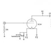
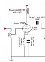
I'm having trouble coming up w/ a biasing plan... Other peoples schematics are confusing me. I'll attach a couple.
Basically, this is a DHT with a 3amp heater. Everyone has them configured for self bias with a cap and resistor on the filament. But they're using 800-1000 ohm 2 watt resistors.
My limited knowledge tells me a DHT configured this way is in filament bias, so that resistor is passing the full 3 amps of power. And in that case should be more like 1 ohm and 12watts to raise the cathode 4ish volts.
What am I missing here? I must be wrong about something, but I dont know what.
Attachments
Thinking about it.. Is the entire heater supply (transformer windings and all) elevated by that resistor, rather than flowing through it?
Can I do that w/ regulated DC filaments? I guess, because I lift the DC heater voltage in other preamps, but those are indirectly heated.. Then the entire regulator is floating...
Can someone explain the difference between that and filament bias?
Can I do that w/ regulated DC filaments? I guess, because I lift the DC heater voltage in other preamps, but those are indirectly heated.. Then the entire regulator is floating...
Can someone explain the difference between that and filament bias?
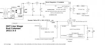
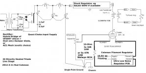
Hopefully, the 2 schematics here will show the circuit differences between Cathode bias and Filament bias, using my Regulators (self-assembly kits).
The circuits are both examples for using the 26 DHT, but it can be adapted to some other DHTs.
With Cathode bias, the transformer-secondary, and raw dc capacitors are floating. You can have anywhere up to 500V or more of cathode bias-voltage, and the filament regulators will not be affected (provided the trafo and heatsink interface are properly isolated).
With the filament bias version of the 26 preamp, notice how the cathode resistor is supplied with the full filament current. Unlike the previous circuit, the Regulator must supply the full output voltage: Filament voltage + bias voltage.
With the standard semiconductors, the Coleman Regulator can operate at up to 42V output, even for 3A filaments. Sadly, the 3C24 in Filament bias is unlikely to be a good solution though - with 3A of current, and (say) 30V of bias: the Bias Resistor burns 90W of power! This is not really a practical proposition.
However many DIYers enjoy the 26 and the 4П1Л (4P1L) in filament bias, using my Regulators, since the typical burn is about 10W and 5W respectively.
Attachments
<snip>....... And in that case should be more like 1 ohm and 12watts to raise the cathode 4ish volts.
What am I missing here? I must be wrong about something, but I dont know what.
If your desired operating point only requires 4V of bias, the 12W of burn in the bias resistor is not too impractical! This is easily achieved, with some reasonable heatsinking, and proper ventilation, or a low-speed quiet fan.
The motivation for filament bias: to bias the tube without a cathode capacitor (which would usually be horrible-sounding electrolytic).
In filament bias one side of the filament regulator output is grounded at audio circuit ground, and the other side goes to the filament; then from the other end of the filament there is a resistor to ground. It would be very small, 1 ohm or so like you wrote earlier.
It's completely ok to float the whole regulator. Just take the other end of the filament (the positive end) and use that to make normal cathode bias via RC or LEDs.
I use these at 650V plate voltage, 1000V B+, and about 20mA current, in CCS tailed class A balanced topology. Swings quite a few volts. =)
These tubes have a high plate resistance to be used with transformer loads. I would suggest two routes to go around this:
1) Use a balanced pair, with a CCS in the tail, and simple one MOSFET gyrators on both plates. Put the output transformer between the plate load sources, with a quality capacitor on one side (doesn't matter which side of course). Balanced parafeed. Will drive even a cheap OT with incredible punch!
2) Single ended parafeed with gyrator plate load. Put a quality capacitor between plate load source and the OT. Other end of OT primary grounded. Also put a CCS configured for 10mA or so between plate load source and ground. This will drive the OT very well with excellent results.
Both these will produce superb sound from this DHT. Great bass with all the dynamics and DHT magick and all that.
Number one will produce less distortion, but cost more. Number two has a possibility of making a great small power output stage if you increase the CCS current some.
Thanks! I see the difference in the schematics, and understand why people go for filament bias in their quest for perfection.
I like the LED idea, or maybe diodes to raise the voltage.
gyrators were in my plan already. I don't want to buy transformers, but understand I may have to. Everyone seems to put big chokes on the plates. I have some 3.5k se. tx's and some pp outputs from a 6v6 amp.. I doubt I could use either of those for line out.
Thanks for the info, I'm going to continue going forward for now.
I haven't tried myself the 3c24, however I heard some great comments about its sound. Of course it's an overkill but I'm not the one to say that. I'm using a 46 in filament bias using Rod's regulators. That is an overkill (32W) on filament resistor power! The results are fantastic in terms of drive capability and sound.
My output stage is a 814 with DC filaments (10V@3.25A) using Rod's regulators as well. Version 4 is optimised with temperature compensation which works great. I can say I get absolutely no hum on my systems which uses high-efficiency speakers (FE167). That is a hard achievement, and could only be possible with Rod's regulator. The sound quality is sterling. My pre / line stages also use Rod's regulators (e.g. 26, 01a, 10Y, 4P1L, etc.). Filament sound is worth implementing and a nice step down 4:1 or 5:1 OT is worth investing (e.g. LL1660 / LL2745). A mu-follower gyrator (e.g. DN2540) is also great and does sound fantastic. Strong bass but then will push the preamp to maximum gain (mu) and that is not something you may want to in many scenarios.
Keen to hear about your listening impressions of the 3C24...
cheers,
Ale
A few more questions, before I really dig in....
I don't understand the CCS. Is it in parallel w/ the tube? Can you direct me to schematics or more information about it?
Then in general, is there a benefit to parafeed with a 5 to 1 line out tx (no gap, maybe magnequest b7 series) vs a gaped SE output (also about 5 to 1) like the ll1660 or ll2745?
And last question, like I mentioned earlier in the thread, people are operating these tubes all over the map. A lot of people seem to be using them as drivers burning about 4 watts, which is far below "cherry plate" dissipation. I'm wondering how much the cherry plate getter thing matters.
I'm basically limited by my voltage regulator (SSHV2). I don't think I can go much over 400v. I want as much inductance as possible on the plate which limits my current if I use a choke or SE output... Maybe this is why parafeed w/ a gyrator becomes a benefit. Or maybe I need to find another plan for my power supply.
I guess the cherry plate thing is the next important piece of info I need. If I need to burn about 15 watts for the getter function, that basically means I need to go w/ the parafeed option. (400v 35ma) If I can get away w/ 10ma current, I can think about the SE option.(but that's only 4watts).
2) Single ended parafeed with gyrator plate load. Put a quality capacitor between plate load source and the OT. Other end of OT primary grounded. Also put a CCS configured for 10mA or so between plate load source and ground. This will drive the OT very well with excellent results.
I don't understand the CCS. Is it in parallel w/ the tube? Can you direct me to schematics or more information about it?
Then in general, is there a benefit to parafeed with a 5 to 1 line out tx (no gap, maybe magnequest b7 series) vs a gaped SE output (also about 5 to 1) like the ll1660 or ll2745?
And last question, like I mentioned earlier in the thread, people are operating these tubes all over the map. A lot of people seem to be using them as drivers burning about 4 watts, which is far below "cherry plate" dissipation. I'm wondering how much the cherry plate getter thing matters.
I'm basically limited by my voltage regulator (SSHV2). I don't think I can go much over 400v. I want as much inductance as possible on the plate which limits my current if I use a choke or SE output... Maybe this is why parafeed w/ a gyrator becomes a benefit. Or maybe I need to find another plan for my power supply.
I guess the cherry plate thing is the next important piece of info I need. If I need to burn about 15 watts for the getter function, that basically means I need to go w/ the parafeed option. (400v 35ma) If I can get away w/ 10ma current, I can think about the SE option.(but that's only 4watts).
I'm doing some initial testing w/ this tube... (I'm going the gyrator/parafeed route for now, so I can try a greater range or operating points)
Everything is working as calculated except the grid is never at ground. I have about 500v on the plate, and calculated what I'd need for about 4 volts on the cathode. That works out great.. But then I have 7v on the grid.
When I increase the cathode resistor and get about 24v on the cathode, the grid is at 26v!
The grid has a 100k resistor to ground.
Can anyone tell me what is going on there?
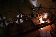
Here's a photo for no reason.. (Doing a few experiments at once.. This preamp won't have 866a rectifers)
Everything is working as calculated except the grid is never at ground. I have about 500v on the plate, and calculated what I'd need for about 4 volts on the cathode. That works out great.. But then I have 7v on the grid.
When I increase the cathode resistor and get about 24v on the cathode, the grid is at 26v!
The grid has a 100k resistor to ground.
Can anyone tell me what is going on there?
Here's a photo for no reason.. (Doing a few experiments at once.. This preamp won't have 866a rectifers)
Attachments
I lowered the voltage and have about 350 on the plate. ~4v on the cathode(1k). The grid is still always a volt or two higher than the cathode. I've seen a few schematics where they use the 3c24 as a driver at about those parameters, so it should be working..
The first tube I tried was bad.. I'm starting to think maybe they're all gassy.
The first tube I tried was bad.. I'm starting to think maybe they're all gassy.
2V/100K=20uA, that's not a lot of power and the grid is rated for 7 watts so not really a problem however my experience has been that using lower valued grid resistors can sound a lot better. Have you seen what happens with a lower value? High inductance grid chokes can be excellent as well. High impedance/ Low DCR.
The other thing is the getter. To my knowledge , the hams who were contemporary users of the technology seemed to take it as given that you had to run the tantalum hot otherwise no gettering action - I don't think the fact that you or I might consider the power supply needed to do that an inconvenience has any bearing on the physics.
Have a look at this page I remember seeing posts years ago from the early triode revival crowd (joelist etc) that running them too cool made them go bad quickly. I played with a couple of 24G's without knowing that and in a fairly short time both tubes started to give me trouble. I packed in the experiment before learning this so don't know if running them hot could have revived them or not - they're still here in a box somewhere . . . . . . . . My advice though would be to follow directions of manufacturers and old hands.
A fellow named Jim Dowdy used them a lot and said that in his experience they always sounded best at 400V and up (or words to that effect). I think most of his online posting is probably over at the Audio Asylum. (Do "All forums" searches)
Thanks! I did read Jim Dowdy's posts at AA, and have set mine up to his suggested parameters.. But am still getting all that grid current. I know the tubes are designed for grid current, so no harm to them. But I don't want the input to my preamp sitting up at +20 or even +2v.
I found another post by Jim (or someone) at AA saying to run the filaments only for 24 hours, and that should heat them up enough to clean up some of the gas.. I left one on all night. I'll have some time later to see if it made any difference.
I found another post by Jim (or someone) at AA saying to run the filaments only for 24 hours, and that should heat them up enough to clean up some of the gas.. I left one on all night. I'll have some time later to see if it made any difference.
I am Jim Dowdy - I have quite a bit of experience with the 3C24, primarily as V1 in two-stage all-DHT amplifiers. I've run them for years at 400 to 500 vpk, drawing 8 to 10 mA per tube.
If your tubes are gassy, it is possible that they can be rehabbed by running them under red plate conditions for a few minutes.
Hope this helps.
Jim
If your tubes are gassy, it is possible that they can be rehabbed by running them under red plate conditions for a few minutes.
Hope this helps.
Jim
If your tubes are gassy, it is possible that they can be rehabbed by running them under red plate conditions for a few minutes.
Jim, are you suggesting that after they are degassed the plate dissipation can be lowered out of the red, or did you run them red for normal operation?
Thanks
- Status
- This old topic is closed. If you want to reopen this topic, contact a moderator using the "Report Post" button.
- Home
- Amplifiers
- Tubes / Valves
- 3c24 preamp?