I have a pair of 833a monoblocks. Currently undergoing mods to take them to mk3 version.

I can feel the radiant heat from here across the pond! Safety aspects aside, that's definitely a fun project! How high is your killer B+ ?
Actually, it's not that high.")
I was advised that 1,000V was minimum for good results, but with the PSU bits I had to hand iv'e "only" managed about 950V HT
First version used my 300b SET amp via a 5K output transformer on the 16R tap to drive the 833a grid, sounded very nice. Version 1A used a small interstage transformer at about 1 :4.5 ratio, but that was less successful.
Current version (mk 2) uses a 6SN7 and EL34 (as cathode follower with fixed negative bias) to drive 833a.
Next version will give a negative supply to the EL34 cathode to correct a slight anomaly on the waveform that the scope found.
Philip Ramsey (Bluebell Audio) is trying to get Hammond to make some special interstage ( about 6:1 from memory) driving transformers, as he thinks that is the best way. I'm sure going to want to try them when (or if) they become available.
High power Amp
Why nog make an 4CX250b SE -Amp,about 65Watts and 1000-2000 V ,Anode,grids stabilized.
Big Supply transformator end Big SE trafo.
Used an ECC83,and an EF183 for drive.
Searcing for trafo will be difficult,but fun.
Also PP is possible Output would be around 200Watts,8Ohm use an 4 Ohm tap,to drive the 8Ohm will make an very stable Amplifier,with around 85Watts.
For more info please contact me.
Good afternoon,
you must admit.....this thread is getting longer/better every time. It started all with Protos asking for 833-amps and now it seems there are serious plans and even builded amplifiers with this tube !
NickC: your right about the open structure of the tube socket. It is rather exposed. Nonetheless the anode-connection with 1000 V (in my case) is more a problem. A standard topcap will fit perfectly for the wire, but a part of the connection (metal !) is still exposed. Although the heat of the tube will certainly make you think twice of touching it........can you take the risk with children ? That's why i've build an open frame with ventilation holes in it. If there are visitors with children i simply install the frame. The tube cn still loose it's heat but the holes are to small for even tiny fingers to touch the 833 at all. It works but i do not like it; so now i'm experimenting with a teflon pipe that slides over the top cap. If i'm happy with it i'll post a picture. Now you have to do with the frame-solution (picture in next post).
Back to the tube sockets. I am happy to have found a pair. But asking for 4 for your PP-design is pushing. But i will be on the look-out for you (and all other 833-builders).
There are 2 varieties of sockets:
- the Johnson. Altough a rather simple clamping-system the mounting can be swiffeled 90 degrees ! And that is very handy indeed. The ceramic base can be fixed to a wall or base (horizontal or vertical) and the tube can be how YOU want it ! Which is in almost all designs standing proudly vertical. I'm going to post a picture some post from now which is absolutely NOT good. And that's even a commercial item.
- The RCA and ITT. Their clamping system is more sophisticated, but the whole tube socket is fixed....so less flexible in your design.
Enclosed is a picture of a ITT (=fixed) socket and a Johnson with one of the filament clamps 90-degrees swiffeled as an example.
Reinout
Where does one find these? I can't find them in America
I use the Chinese ceramic type.
Available on Ebay.
SOCKET SOC833 TO FIT 833A AND GU48 ETC VALVES / TUBES TOP CAPS AVAILABLE ALSO | eBay
1pc 2pin Ceramic Tube Socket For 833 833A GU48 FU33 PL833A Valve,21
Or, if you are wealthy,
833A GU48 TEFLON SOCKET, Pair of sockets for Power tube 833A GU48, valve,vacuum | eBay
Available on Ebay.
SOCKET SOC833 TO FIT 833A AND GU48 ETC VALVES / TUBES TOP CAPS AVAILABLE ALSO | eBay
1pc 2pin Ceramic Tube Socket For 833 833A GU48 FU33 PL833A Valve,21
Or, if you are wealthy,
833A GU48 TEFLON SOCKET, Pair of sockets for Power tube 833A GU48, valve,vacuum | eBay

I use the Chinese ceramic type.
Available on Ebay.
SOCKET SOC833 TO FIT 833A AND GU48 ETC VALVES / TUBES TOP CAPS AVAILABLE ALSO | eBay
1pc 2pin Ceramic Tube Socket For 833 833A GU48 FU33 PL833A Valve,21
Or, if you are wealthy,
833A GU48 TEFLON SOCKET, Pair of sockets for Power tube 833A GU48, valve,vacuum | eBay
well I was looking for the ef johnson mounts lampizator does make some extremely nice mount just tooooo much money fir my taste.
Hi all,
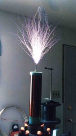
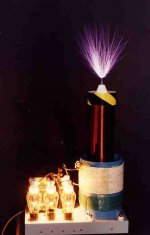
so if your 833-based amp fails you can always built your own tesla coil with it.
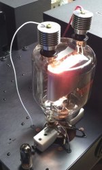
No....this is not at my house; my 833's are up and running with music. I found these pictures surfing across the web. Still interesting: again the "spot" on the anode is clearly visible.
What kind of amp would this be ? Class Z ?
Reinout
Reinout,
You managed to find photos of my 833A 'magnifying transmitter' type Tesla coil from a lab bench experiment in the late 1990's. The HV resonator coil does not sit inside a conventional primary coil but is bottom end fed by a clip lead wire visible in the photo. I sprinkled some WE313C neon triodes with the black paint removed around the plastic wire spool base to show the presence of the HF HV field. The discharge is 22" long. This power oscillator operates the triode in Class-C. A large MOT (Microwave Oven Transformer) with SS doubler diode working with the 833A as the 'other diode', puts about 4 kVDC on the 833A anode. I made a previous coil system using three 810's in parallel and this single 833A circuit completely kicked it's butt in discharge spark length utilyzing a somewhat smaller HV resonator as well!
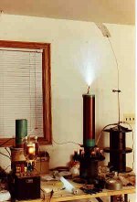
Also shown is a coil I made with four parallelled 811A's. Similar HV resonator. The 811A is NOT a beefy enough tube for such application. Save them for the old Altec theater amplifiers that used them. In the amp app they won't melt out their grids. IMO, the 833C is the best triode for homebrew Tesla coils. Parallel as many as you need!
Attachments
Last edited:
Where does one find these? I can't find them in America
I gave up on finding the Johnson sockets and just made my own from scrap teflon and aluminum lugs from Home Depot, like these:
Blackburn #1/0 Stranded Max Type ADR 2-Conductor 1-Hole Dual-Rated Lug-ADR11-B1-5 - The Home Depot
They have a couple different sizes, I used the one that fit the 833 legs best. Works like a charm.
I thought I might have an issue with expansion and contraction but it seems the teflon is pliable enough and allows enough wiggle that it isn't an issue. More than two years now with no problems.
Attachments
833A in P-P
I had the idea of using a pair of 450TH's in P-P as a subwoofer mono amp. I have decided that this is not really practical, especially given the cost of this tube and the high voltage it needs to output the kind of power I was after. The repurposed Hammond plate xfmer I was hoping to use as output iron was not insulated sufficiently for the application. I don't want to subject it to more than about 2 kVDC.
I have decided that if this is to end up being built at all, it will be with 833A's instead.
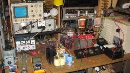
I have built up enough of a test circuit on the lab bench to determine a few things. First, smooth DC at 10 VDC is absolutely necessary for the filaments to avoid hum.
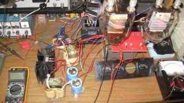
Here is my test setup with 1800 VDC on the plates and 140 mA anode current each tube. I was getting about 550 watts RMS out into an 8 ohm resistive test load before I ran out of grid drive. I was using a low power SS receiver with speaker terminals driving a backwards P-P output xfmer as the P-P grid drive. I have been using about 25 or 30 VDC negative grid bias. Less and the plates will melt at this anode voltage. Since the last experiment I have replaced the receiver with a powerful 100 watt/channel Technics but need to experiment with the drive circuit yet.
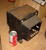
From 20 Hz to about 13KHz this actually sounds pretty good. To get the response flattened out and improve the sound I am running some NFB derived by a torroidal power xfmer driven from the audio output to impress NFB on the 833A grids. A bit of NFB really improved the sound and character of the amp. Remember, I'm using an ancient 25 Hz plate xfmer from a prewar RCA AT-3 HF transmitter as an output xfmer here. This shouldn't sound as good as it does. I tested about half a dozen plate xfmers for this duty and they all sounded horrible, except this particular hard to find treasure. Since first posting about this I have acquired the other AT-3 plate transformer that was still existent on the planet, so now I have a pair and could build a stereo pair of monoblocks. Fortunately I have a large junk box containing many precious HV tube components from a pair of RCA BTA-10K AM broadcast xmitters that I acquired and parted out years ago. Don't need to spend money in order to do development work. Good thing since these parts are now so pricey and money is one thing I ain't got any of.
This is an extremely back burner project after survival, so could be a while before I next get to play with it.
I had the idea of using a pair of 450TH's in P-P as a subwoofer mono amp. I have decided that this is not really practical, especially given the cost of this tube and the high voltage it needs to output the kind of power I was after. The repurposed Hammond plate xfmer I was hoping to use as output iron was not insulated sufficiently for the application. I don't want to subject it to more than about 2 kVDC.
I have decided that if this is to end up being built at all, it will be with 833A's instead.
I have built up enough of a test circuit on the lab bench to determine a few things. First, smooth DC at 10 VDC is absolutely necessary for the filaments to avoid hum.
Here is my test setup with 1800 VDC on the plates and 140 mA anode current each tube. I was getting about 550 watts RMS out into an 8 ohm resistive test load before I ran out of grid drive. I was using a low power SS receiver with speaker terminals driving a backwards P-P output xfmer as the P-P grid drive. I have been using about 25 or 30 VDC negative grid bias. Less and the plates will melt at this anode voltage. Since the last experiment I have replaced the receiver with a powerful 100 watt/channel Technics but need to experiment with the drive circuit yet.
From 20 Hz to about 13KHz this actually sounds pretty good. To get the response flattened out and improve the sound I am running some NFB derived by a torroidal power xfmer driven from the audio output to impress NFB on the 833A grids. A bit of NFB really improved the sound and character of the amp. Remember, I'm using an ancient 25 Hz plate xfmer from a prewar RCA AT-3 HF transmitter as an output xfmer here. This shouldn't sound as good as it does. I tested about half a dozen plate xfmers for this duty and they all sounded horrible, except this particular hard to find treasure. Since first posting about this I have acquired the other AT-3 plate transformer that was still existent on the planet, so now I have a pair and could build a stereo pair of monoblocks. Fortunately I have a large junk box containing many precious HV tube components from a pair of RCA BTA-10K AM broadcast xmitters that I acquired and parted out years ago. Don't need to spend money in order to do development work. Good thing since these parts are now so pricey and money is one thing I ain't got any of.
This is an extremely back burner project after survival, so could be a while before I next get to play with it.
Attachments
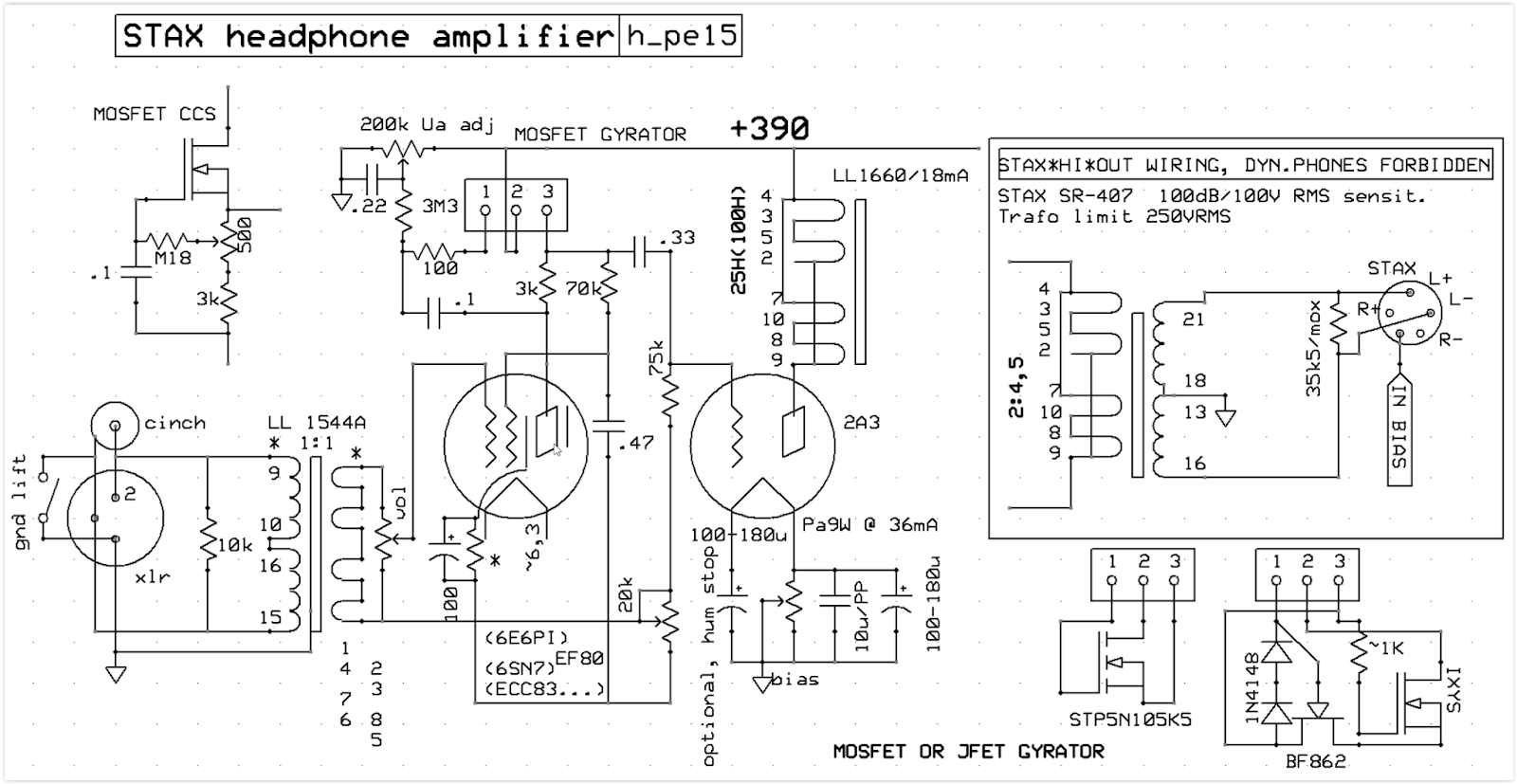
I use the 833-A at 1KV and zero grid bias. The cathode is a 20 Amp rated 10 Volt transformer, a 50 Watt rated bridge, 82,000 micro-Farads, 0.1 Ohm, and a pre-charged 4.5 Farad capacitor. I drive it with a 50 Henry choke, at least 2 micro-Farads, and an LL1930 step-down transformer 5K to the low impedance windings in series and a 45 driver tube. This gives me a full-bodied sound which I will use with Magnepan 0.7 speakers.
no 833, but graphite plate atleast the almighty QY3-125
bought some acdc 5v converters, works purrrrrrrfect.
basically, i kicked out the 2a3´s, and replaced them by these gherkin pots.
sound is wonderful.
what i found -- you can use xmitter tubes under 1kv a1, but only as low current.
amp schema (without fb driver loop):


the almighty QY3-125bought some acdc 5v converters, works purrrrrrrfect.
basically, i kicked out the 2a3´s, and replaced them by these gherkin pots.
sound is wonderful.
what i found -- you can use xmitter tubes under 1kv a1, but only as low current.
amp schema (without fb driver loop):
Attachments
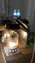
 It sure looks the business!
I made the power supply out of a Hammond 724 transformer and solid state fast reacting 5000 Volt rated diodes with the center tap to the transformer grounded, then I strung groups of three electrolytic capacitors rated at 600 Volts each, two gangs of 56 micro-farads per capacitor for a total of sis capacitors, followed by a Hammond 193M 10 Henry choke which I mounted inside a Plexiglas cage because it can't isolate more than 800 Volts, and followed this with two gangs of three 100 micro-farad capacitors.
Attachments
- Home
- Amplifiers
- Tubes / Valves
- Where are the 833 amps?