Hello Reinout,
what are the items to the right? chokes for the filament??
I was thinking of using switching power supplies for the filaments, 2 supplies of 5V in series.
These can be had cheaply surplus, and should be quite sturdy and efficient. (and some also have 12V, which could be used for a 12sn7...)
For the gm70 I used an lm* regulator, since a 20V filament isn't quiet on ac. But a regulator like that for 10A is difficult to cool. Even a bridge rectifier needs decent cooling with 10A running through it.
I would probably go for a one block affair, like the wavac once. So this time solid state recification. (just to gain some space, a pair of 866's takes up a lot") .
.
Filip.
what are the items to the right? chokes for the filament??
I was thinking of using switching power supplies for the filaments, 2 supplies of 5V in series.
These can be had cheaply surplus, and should be quite sturdy and efficient. (and some also have 12V, which could be used for a 12sn7...)
For the gm70 I used an lm* regulator, since a 20V filament isn't quiet on ac. But a regulator like that for 10A is difficult to cool. Even a bridge rectifier needs decent cooling with 10A running through it.
I would probably go for a one block affair, like the wavac once. So this time solid state recification. (just to gain some space, a pair of 866's takes up a lot
.Filip.
coreless coils
Hi Peter,
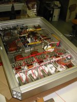
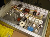
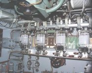
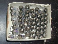
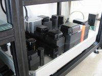
all the items on the right are "coreless coils". I'm using them after the rectification before the current dumps into the first capacitor. These coils act as very small chokes and just smooth out the current which you get with rectifiers.
A capacitor does like to see a stable current flow. So these items are just for getting the max lifetime of the caps.
The coils are in the mH-scale. I found out that the actual gain of a complete choke at that place was very small, so i stuck with the much smaller coreless coils.
Tried and tested on severall other projects: RIAA-stage (and that HAD to be "silent"), preamp, headphone-amp.
Standard my powersupply is following the next "schematic":
transformer - rectifier - snubber (get the possible spike out) - coreless coil (smoothing) - first capacitor - choke - second capacitor.
So after the combination corelss coil/capacitor there is the classic choke/capacitor combination.
I do not use drop-resitors to get a lot of different voltages from one single power line. All possibly needed voltages have their almost exclusive own powerline:
- combined transformer for filaments 6SN7/300B. After the transformers the 5 VDC and 6,3 VDC powerlines have their own rectifiers, snubbers, coils, etc.
- combined transformer for B+ 6SN7/300B. Same story. And i included the bias 300B as well.
- complete seperate transformers and powerlines for the filament and B+ of the 833. Did you expect something else with this tube ?
The reason for grouping these voltages together in seperate transfomers is that different voltages taken from one single transformer always influence each other. Sometimes more/less than other. I simply do not like to take (example) 400 V and 5 Volt out of one single unit. Grouping the filaments (5 and 6,3) or the B+ (400 and 250) together is of course a trade off. If i really wanted to be a purist i had ALL complete seperate powerlines. In my case 3 x 2 transformers extra. But i thought it was large enough already.
I'll enclose a picture of the inside of a 833-powersupply. In front you'll see the seperate powerlines for 6SN7 and 300B with the coreless coils.
Reinout
Hi Peter,
all the items on the right are "coreless coils". I'm using them after the rectification before the current dumps into the first capacitor. These coils act as very small chokes and just smooth out the current which you get with rectifiers.
A capacitor does like to see a stable current flow. So these items are just for getting the max lifetime of the caps.
The coils are in the mH-scale. I found out that the actual gain of a complete choke at that place was very small, so i stuck with the much smaller coreless coils.
Tried and tested on severall other projects: RIAA-stage (and that HAD to be "silent"), preamp, headphone-amp.
Standard my powersupply is following the next "schematic":
transformer - rectifier - snubber (get the possible spike out) - coreless coil (smoothing) - first capacitor - choke - second capacitor.
So after the combination corelss coil/capacitor there is the classic choke/capacitor combination.
I do not use drop-resitors to get a lot of different voltages from one single power line. All possibly needed voltages have their almost exclusive own powerline:
- combined transformer for filaments 6SN7/300B. After the transformers the 5 VDC and 6,3 VDC powerlines have their own rectifiers, snubbers, coils, etc.
- combined transformer for B+ 6SN7/300B. Same story. And i included the bias 300B as well.
- complete seperate transformers and powerlines for the filament and B+ of the 833. Did you expect something else with this tube ?
The reason for grouping these voltages together in seperate transfomers is that different voltages taken from one single transformer always influence each other. Sometimes more/less than other. I simply do not like to take (example) 400 V and 5 Volt out of one single unit. Grouping the filaments (5 and 6,3) or the B+ (400 and 250) together is of course a trade off. If i really wanted to be a purist i had ALL complete seperate powerlines. In my case 3 x 2 transformers extra. But i thought it was large enough already.
I'll enclose a picture of the inside of a 833-powersupply. In front you'll see the seperate powerlines for 6SN7 and 300B with the coreless coils.
Reinout
Attachments
excuses....
Hi Filip,
i called you Peter in my reply. Apologies, apologies. It is a very common name here......
Nevertheless: you're living in Belgium so we're practically neighbours (positive thinking !!!).
You're welcome to hop over. Maybe combined with a audio-show in the Netherlands. I believe there is one on Sunday 28 March in Rotterdam ?!
About your filament supply: very interesting (and much cheaper than my chosen path). Remember that there is an inrush of 20 Ampere......
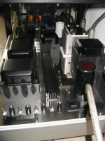
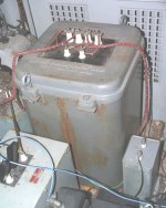
You're quite right on the heat-issue. The filamt-powerline of the 833 is definately the most warm part of the amp. But a nice cooiling heatsink took away that problem.
With picture of the heatsink. The rectifiers are inside the powersupply. They are bolted on a massive aluminium slab for optimum heattransfer. That is bolted to the stainless steel topplate (difficult for taking pictures....mirror) which doubles as a heatsink. On the outside there is a proper heatsink to get rid of the warmth.
Reinout
Hi Filip,
i called you Peter in my reply. Apologies, apologies. It is a very common name here......
Nevertheless: you're living in Belgium so we're practically neighbours (positive thinking !!!).
You're welcome to hop over. Maybe combined with a audio-show in the Netherlands. I believe there is one on Sunday 28 March in Rotterdam ?!
About your filament supply: very interesting (and much cheaper than my chosen path). Remember that there is an inrush of 20 Ampere......
You're quite right on the heat-issue. The filamt-powerline of the 833 is definately the most warm part of the amp. But a nice cooiling heatsink took away that problem.
With picture of the heatsink. The rectifiers are inside the powersupply. They are bolted on a massive aluminium slab for optimum heattransfer. That is bolted to the stainless steel topplate (difficult for taking pictures....mirror) which doubles as a heatsink. On the outside there is a proper heatsink to get rid of the warmth.
Reinout
Attachments
keeping the thread alive...
Hello Reinout,
looks nice, very polished work! I never get mine uptill such a high finish, lack of metalworking tools and too much experimenting....
I try to post a picture of them working in the following days.
Before I start on an 833 amp, I'm first going to try out if I can make a compact 10V/10A DC supply.
I've got an article from Elektuur, that shows how to do it. An old AT supply should be modifyable to 10V/10A, and with some luck (maybe different heatsinks) also work whithout the ventilator. Add in some extra filtering after this supply, and decent shielding. So the switching doesn't couple into the audio. Otherwise it'll be large transformer, large cap, and heatsinked bridge.
I would like these amps to be one block per channel, so saving some space with switched heatersupplies (for things like a kt88 this should also work great), and diodes for the ht rectifiers.
Ofcourse chokes in the 1kV supply, but the 500V supply for the driverstage could use a mosfet regulated supply. The size of the wavac amps is the goal here. It makes the connection a bit simpler. Finding the correct connectors and cabling is quite costly and time consuming.
My current amps are like yours, with seperate powersupplys. (76-300b-gm70. with direct coupling from 300b to gm70....40W of power)
When I measured them (with a soundcard) I was really surprised, they have very low distortion (for a single ended amp). The distortion spectrum only starts to look bad when it goes into A2 at about 24W, a lot more higher harmonics, with about 3% at 40W output.
Ofcourse, measuring isn't the same as listening. But I do feel it can give some indication of the quality and what to expect.
And what am I going to do with the current gm70 amps, if I start an 833 one? re-using them for parts, and replacing the outputtransformer could save a lot of money... although I would really hate to scrap them....
Filip.
Flip
I too am going the gm70 path but mine would be push pull
when the gm70 is done will start on the 833. By 1 year i should have most of the parts. and the gm70 will be used to drive the 833. To save on paths. Have you considering doing ultrasonic AC heating since you are using switchmode. Should yield better results compared to DC. Still looking for 833 though
parts......
Hi Filip,
you face the same "problem" i do. What to do with with the former power-amps ? I had parallel push-pull 300B monoblocks. Again with external power supplys. So 4 x 300B each channel. Lots of energy there with a bass output that kicked butt. Now i've listened to the 833 SE: it's much more "honest" and with drive too.
I did not use the 300B-amps for parts. They served me nice for years and they are really at their peak-perfomance. Maybe i find a new home for them ?
You're looking for compact heatsinks: i got them (see earlier pictures). And i've got still some left in several sizes. What is so nice that i did not have to tap/drill in them. They have already lots of mounting-possibilities with even a thread in them !
Before you start buying parts: please do check if i've got items we could swap to both our benefit ?
I went for the choke/capacitor powersupply for each powerline and that became large. So your design-objective to make a "small" 833-amp is a real goal. That will give you lots of challenges, but you can skip the powerline-umbillicals and the connectors.......
Choices, choices.......
Have a nice building time,
Reinout
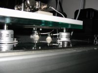
Included a picture of the feed-troughs of the 833-filaments. Becouse the 10V/10A is almost like a car battery i made the connections very sturdy. From the powersupply the connection is made through the topplate with nice ceramic feed-throughs to the tube socket.
Hi Filip,
you face the same "problem" i do. What to do with with the former power-amps ? I had parallel push-pull 300B monoblocks. Again with external power supplys. So 4 x 300B each channel. Lots of energy there with a bass output that kicked butt. Now i've listened to the 833 SE: it's much more "honest" and with drive too.
I did not use the 300B-amps for parts. They served me nice for years and they are really at their peak-perfomance. Maybe i find a new home for them ?
You're looking for compact heatsinks: i got them (see earlier pictures). And i've got still some left in several sizes. What is so nice that i did not have to tap/drill in them. They have already lots of mounting-possibilities with even a thread in them !
Before you start buying parts: please do check if i've got items we could swap to both our benefit ?
I went for the choke/capacitor powersupply for each powerline and that became large. So your design-objective to make a "small" 833-amp is a real goal. That will give you lots of challenges, but you can skip the powerline-umbillicals and the connectors.......
Choices, choices.......
Have a nice building time,
Reinout
Included a picture of the feed-troughs of the 833-filaments. Becouse the 10V/10A is almost like a car battery i made the connections very sturdy. From the powersupply the connection is made through the topplate with nice ceramic feed-throughs to the tube socket.
Attachments
833 workhorses
Hi,
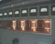
just for historical background i will post 2 pictures of a 833-transmitter (AM radio). The pictures are from a General Electric XT-1.
Of course there are more of these (the common) beasts which were capable of 1000 Watt++:
- Gates BC1-F (early 50's);
- RCA BTA -1R1 (early 60's);
Doesn't your adrenaline starts rushing ?
Reinout
Hi,
just for historical background i will post 2 pictures of a 833-transmitter (AM radio). The pictures are from a General Electric XT-1.
Of course there are more of these (the common) beasts which were capable of 1000 Watt++:
- Gates BC1-F (early 50's);
- RCA BTA -1R1 (early 60's);
Doesn't your adrenaline starts rushing ?
Reinout
Attachments
red plate
Hi all 833-aholics,
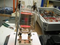
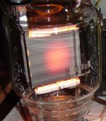
at the start of this thread Tubeman (from Thailand) had some reservations about the 833 plate become reddish. I had the same reservations when my amp was switched on for the first time. But no worries.....it's fine with this tube.
And if you inspect a lot of the 833's which are on offer at Ebay, you'll notice that sometimes the plates have seen serious pounding.
Yesterday i picked up a Westinghouse 833A with obviously some milage on it's counter........
But it does work. So now for finding a second example. That seems to be the hardest part: finding pairs. And there are so many of these tubes. Allmost all well known manufacturers did made them: RCA, GE, Westinghouse, Amperex, Mullard, Tungsram, Polyaron, Nanjing, ITT. I'm 100% for these (have them or seen them)
Who knows more brands ? For sale ?????
Included the Westinghouse with "working-spot".
Reinout
Hi all 833-aholics,
at the start of this thread Tubeman (from Thailand) had some reservations about the 833 plate become reddish. I had the same reservations when my amp was switched on for the first time. But no worries.....it's fine with this tube.
And if you inspect a lot of the 833's which are on offer at Ebay, you'll notice that sometimes the plates have seen serious pounding.
Yesterday i picked up a Westinghouse 833A with obviously some milage on it's counter........
But it does work. So now for finding a second example. That seems to be the hardest part: finding pairs. And there are so many of these tubes. Allmost all well known manufacturers did made them: RCA, GE, Westinghouse, Amperex, Mullard, Tungsram, Polyaron, Nanjing, ITT. I'm 100% for these (have them or seen them)
Who knows more brands ? For sale ?????
Included the Westinghouse with "working-spot".
Reinout
Attachments
Re: 833 workhorses
Don't know about adrenalin, but I'm certainly drooling. Is that a couple of 845 I see in the transmitter? Drivers? I've seen anode burns like that on a friend's 4212.
ReinoutdV said:Doesn't your adrenalin starts rushing?
Don't know about adrenalin, but I'm certainly drooling. Is that a couple of 845 I see in the transmitter? Drivers? I've seen anode burns like that on a friend's 4212.
GE XT-1
Hi EC8010,
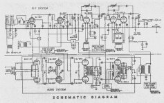
yup......those are 845's. It's a pair which form the push-pull drivers. I've attached the schematic.
EC8010: very nice tube. Difficult to source (for "normal" prices) but with a lot of potential. I was seriously considering that beauty, but stuck with the 6C45 due to it's availability.
Are you considering building a 833 based amp ?
Reinout
Hi EC8010,
yup......those are 845's. It's a pair which form the push-pull drivers. I've attached the schematic.
EC8010: very nice tube. Difficult to source (for "normal" prices) but with a lot of potential. I was seriously considering that beauty, but stuck with the 6C45 due to it's availability.
Are you considering building a 833 based amp ?
Reinout
Attachments
Wow! 845 push-pull cathode followers. Hmmm. That says a lot about how much grid current an 833 is likely to pass. I remember going to a transmitting station and seeing diagrams like that stuck on the side of the transmitters.The difficult bit was relating the diagram to the physical components. What I initially thought was an oversized filing cabinet turned out to be the modulation (output) transformer for an audio amplifier.
I wouldn't say "stuck with" 6C45 rather than EC8010, they're both very nice little valves, and the 6C45 has rather better mutual conductance (but huge production spread).
I think I have to regard 833 as impractical, but that doesn't mean I'm not full of admiration for you in making such a beast!
I wouldn't say "stuck with" 6C45 rather than EC8010, they're both very nice little valves, and the 6C45 has rather better mutual conductance (but huge production spread).
I think I have to regard 833 as impractical, but that doesn't mean I'm not full of admiration for you in making such a beast!
grid-hungry
Hi EC8010,
The output stage wasn't that difficult. You just need huge hunks of iron and caps. The designing of the driverstage was far more challenging. I went for a 300B with a step-down transformer. That was "potent" enough to get the 833 to work !
And about the 6C45: your're quite right. I bought a couple of dozens when this tube was not discovered by the audio-scene. Really well build, this tube can take some serious abuse. No broken ones or malfunctions, but it was wise to buy a stack. So now i could match them into pairs, quads, etc. They simply are very prone to "fluctuate", which is not difficult to understand if you see the pitch of the gridwire.....
The 833 impractical ? It's just how you look at it. For me this is the limit because of the high voltages and hefty amperages. But i do know people how play with GM100's, 450TL's, 250TL's, 304TL's.
After years playing/improving my former 300B PPP amp (so 4 x 300B each channel) i thought it was time for a new amp with enough power/headroom. And i did not want to use the obvious choice = 211/845 or go to the boutique-tubes (all the newer 300B-derivates on anabolics).
It was a choice of the 808, 100TL, 838. It became the 833 for it is still in production and the price is really good. You get a massive piece of tube for your money. Even NOS is still around.
Of course there are more choices, but there are also commercial amplifiers using this tube: so it could not be that bad.
Reinout
Attachments
iron for a 833-transmitter
Hi EC8010,
found a picture of your 833-iron. It's a 350lbs UTC-monster from the XT-1 transmitter (UTC LS-692).
Now THAT is a serious transformer, and that is really over-the-top for audio-applications. The largest transformer i saw ever on an audio-amp were on huge Jadis-amps. If i remember correctly is was a Jadis 400 or 800 ?
I'm using a E126-size OPT. More than enough for my application.
With regards,
Reinout
Attachments
zirconium coated anode
Hi 833-fans,
if you look closely at the Westinghouse tube you can actually see some "molten stuff" on the outside of the hotspot. What is it ?!
When checking the tube manuals i've found out that (quote RCA) "the 833a has a zirconium coated anode".
So the next question: what is that stuff doing there. Happily i've found out on several sites that the zirconium is a very often used getter-material.
Several quotes form different sites:
"....example, zirconium is used on the outside of graphite or molybdenum anodes in 3-500Z and other tubes. It is the dull gray powdery or grainy texture coating you see on the surface of 3-500Z, 811A, and 572B anodes..."
"...Zirconium getters best at about 1000 degrees C, this is why large metal anode transmitting tubes like the 4-400A, 4-1000A, and 3-500Z must be operated with a dull red to red anode color. Zirconium also releases some gasses and absorbs other gasses at various temperatures. The varying temperature across the length of the anode (and as the anode heats and cools) allows the gettering agent to absorb a wide variety of gasses...."
"....The quickest way to ruin a 3-500Z, or other glass power grid tube, is to never show anode color over a prolonged period of time!..."
In practice:
- the 833A has 2 getters: one made out of zirconium and applied to the anode. It works best at higher temperatures. Tubeman (Thailand), your anode was emitting a red spot: that is EXACTLY the way to go in order to have the zirconium working as it should. The other getter is mostly a barium-derivate and applied by means of flashing like almost all tubes. The flashed getter has it's optimum at lower temperatures and does absorb other gasses.
- the 833C has only the flashed getter. The carbon anode itself functions as a getter.
Not to much theory i hope, but now i know for sure: fire up those 833's !
Attached: the correct colour......for minimum ?
Attachments
Choke for 833A power supply
Hi All , Reinout !
How are you ?
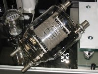
Reinout ! I just received a pair of DC Choke for the power supply
from my friend . Why it's very big choke and heavy.
The specifications from name plate are 11 Henries at 500mA ,65 ohm DCR and tested at 10,000V Rms.Manufactured by Chicago transformer USA.
It's bigger than 833A tube and I show you at a picture.
Can I use it for 833A power supply ?
thank you!
tubeman (Thailand)
Hi All , Reinout !
How are you ?
Reinout ! I just received a pair of DC Choke for the power supply
from my friend . Why it's very big choke and heavy.
The specifications from name plate are 11 Henries at 500mA ,65 ohm DCR and tested at 10,000V Rms.Manufactured by Chicago transformer USA.
It's bigger than 833A tube and I show you at a picture.
Can I use it for 833A power supply ?
thank you!
tubeman (Thailand)
Attachments
Long live the weight-factor !
Hi Tubeman,
those are serious hunks of iron ! Congratulations, they should help to have a very smooth high voltage for your project.
What i really like:
- nicely low DCR;
- 500 mA.....more than enough with spare;
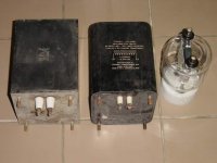
- nice cases. And even sometimes these older stuff had a mumetal inner-lining which surpressed stray fields. I don't know if these have that.....but they sure look like "USE ME";
Questions:
- i see that there are 2 different chokes ? Or do you have the ultimate luxery that you have 2 of both of them. Just for the looks it would be nice to have identical chokes. And of course for the metalwork on the topplates.
- 10 kV test voltage. Sufficent......but what is the continous rating ? I know a lot of transformers which can withstand peakvoltages of several kV's, but their rating is only in the hundreds of volts. Please check if they are within your working range.
Chicago Transformer USA is a well respected firm which manufactured a lot of trannies for transmitting use. Open any of the older large (military) transmitters and don't be surprised if you spot UTC or Chicago Transformer stuff. On Ebey they sometimes pop up, but with prohibitive pricing. And even with a high figure pricing.....to be honest.....my new-made chokes were not for free.......
About my chokes and transformers. They are newly made, so no "respectable goodies with history". But i had the advantage to use more modern material. Normally between windings in transformers Kraft-paper is used to isolate the windings. With higher quality stuff the transformer is impegnated in oil/laquer. Very high quality stuff has the impregnation done under vacuum in order that the oil really reaches the innards of the coil. After that the oil must be hardened in an oven for hours. By means of this routine the windings are REALLY mechanical tight so they will not buzzzzzzz......
Lesser quality transformers do not impregnate at all, or use a simple laquer-spray on the outside (of no use at all).
The Kraft-paper has the nice advantage that it absorbs some oil. And during the hardening process the paper doubles as isolator and as a mechanical strengthening.
The paper is comperatively thick and can "only" withstand 1 kV. Of course that's an average and completely dependand on the brand/type. If you need the withstand more than 1 kV the solution is simple: more paper which now becomes really thick. But putting more (necessary) paper means less space for the copper windings itself. and you simply NEED a certain amount of turns to reach your desired goal (Henrys in chokes or impendance/ratio's in transformers). With less space that will mean: thinner wire. And that is to be avoided ! with thinner wire you'll get a higher DCR or the wire can not withstand the current you want to pass through them.
Solutions:
- thicker core.....more space....see your own chokes. The obvious solution but the will weigh more / use more place / are expensive.
- better isolation material. I've found Kapton-foil. That can withstand 7.5 kV (brand/type-dependand), can be oven-hardened and is very thin.
I spotted a nice roll of that stuff on Ebay. Now i use a mix of Kraft-paper and Kapton with good results. So my transformers and chokes are comperatively small for their ratings (see picture...i've put a floppy for reference next to the HV-tranny.
But whatever you do: when using the 833 you can not build small.
Happy building,
Reinout
Hi Tubeman,
those are serious hunks of iron ! Congratulations, they should help to have a very smooth high voltage for your project.
What i really like:
- nicely low DCR;
- 500 mA.....more than enough with spare;
- nice cases. And even sometimes these older stuff had a mumetal inner-lining which surpressed stray fields. I don't know if these have that.....but they sure look like "USE ME";
Questions:
- i see that there are 2 different chokes ? Or do you have the ultimate luxery that you have 2 of both of them. Just for the looks it would be nice to have identical chokes. And of course for the metalwork on the topplates.
- 10 kV test voltage. Sufficent......but what is the continous rating ? I know a lot of transformers which can withstand peakvoltages of several kV's, but their rating is only in the hundreds of volts. Please check if they are within your working range.
Chicago Transformer USA is a well respected firm which manufactured a lot of trannies for transmitting use. Open any of the older large (military) transmitters and don't be surprised if you spot UTC or Chicago Transformer stuff. On Ebey they sometimes pop up, but with prohibitive pricing. And even with a high figure pricing.....to be honest.....my new-made chokes were not for free.......
About my chokes and transformers. They are newly made, so no "respectable goodies with history". But i had the advantage to use more modern material. Normally between windings in transformers Kraft-paper is used to isolate the windings. With higher quality stuff the transformer is impegnated in oil/laquer. Very high quality stuff has the impregnation done under vacuum in order that the oil really reaches the innards of the coil. After that the oil must be hardened in an oven for hours. By means of this routine the windings are REALLY mechanical tight so they will not buzzzzzzz......
Lesser quality transformers do not impregnate at all, or use a simple laquer-spray on the outside (of no use at all).
The Kraft-paper has the nice advantage that it absorbs some oil. And during the hardening process the paper doubles as isolator and as a mechanical strengthening.
The paper is comperatively thick and can "only" withstand 1 kV. Of course that's an average and completely dependand on the brand/type. If you need the withstand more than 1 kV the solution is simple: more paper which now becomes really thick. But putting more (necessary) paper means less space for the copper windings itself. and you simply NEED a certain amount of turns to reach your desired goal (Henrys in chokes or impendance/ratio's in transformers). With less space that will mean: thinner wire. And that is to be avoided ! with thinner wire you'll get a higher DCR or the wire can not withstand the current you want to pass through them.
Solutions:
- thicker core.....more space....see your own chokes. The obvious solution but the will weigh more / use more place / are expensive.
- better isolation material. I've found Kapton-foil. That can withstand 7.5 kV (brand/type-dependand), can be oven-hardened and is very thin.
I spotted a nice roll of that stuff on Ebay. Now i use a mix of Kraft-paper and Kapton with good results. So my transformers and chokes are comperatively small for their ratings (see picture...i've put a floppy for reference next to the HV-tranny.
But whatever you do: when using the 833 you can not build small.
Happy building,
Reinout
Attachments
Hi all ! , Reinout !
Thank you for your information.
I have only 2 Choke in the picture but same specification ( 11H / 500mA , 10kV )
and different cover metal . I buy it from my friend 1,000 THB/each
2 choke = 2,000 THB = 50 US$ (Not expensive) . Because in Thailand has second hands market for old equipment, old radio Transmitter .My problem is it's too big and heavy.
Thank you
tubeman (Thailand)
- Home
- Amplifiers
- Tubes / Valves
- Where are the 833 amps?