Hi Rongon
Yes, I think you are right. An optical comparison told me, that the 6922EH is much more similar to the 6N23P than to the PhilipsECG 6922.
Plate length is identical, also cathode dimensions. The Grid cannot be compared without destroying a tube, but the tubes where the grid wire is wrapped around are of identical diameter and distance to each other (as far as I can see that with a magnifying glass only).
That makes sense. Electro-Harmonix is a trademark of New Sensor, who sell the Sovtek brand of tubes, made in Russia. The EH tubes are also made in Russia.
The 6N23P is made in Russia, and is their equivalent to the ECC88/6DJ8.
The 6N23P-EV is the super-duper version of the 6N23P, so I guess that would be equivalent to the 'special' E88CC or 6922.
Therefore the EH 6922 is probably a 6N23P-EV. That would be great, because that's a very good twin triode. Or it might be the regular 6N23P, re-branded. I don't know.
Last edited:
Yes, I think you are right. An optical comparison told me, that the 6922EH is much more similar to the 6N23P than to the PhilipsECG 6922.
Hi Adrian,
Have you had a chance to look at the JJ E88CC as well?
The world needs a killer 6922 / E88CC / ECC88 / 6DJ8 model!
(...)
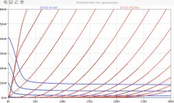
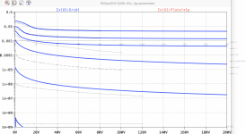
Well, I just finished the PhilipsECG 6922 model, but it will not blow you away.
To be honest, I never had such troubles to get it fitting. In the end, I decided to optimize for Anode current, and accepted a sosolala fit quality of grid current below 1mA.
All my triode models tends to deliver a too high grid current for positive Vg and Va near zero, but this time, this effect was super prominent...

So, it seems that a new generic version i5 is needed, to improve this weak points.
However, here is the model.
all the best, Adrian
Code:
*6922 LTspice model based on the generic triode model from Adrian Immler, version i4
*A version log is at the end of this file
*100h BurnIn of 5 PhilipsECG factory tubes, sample selection and measurements done in April 2021
*Params fitted to the measured values by Adrian Immler, April 2021
*History's best of tube decribing art (plus some new ideas) is merged to this new approach.
*@ neg. Vg, Ia accuracy is similar to Koren.
*@ small neg. Vg, the "Anlauf" current is considered.
*This offers new simulation possibilities like bias point setting with MOhm grid resistor,
*Audion radio circuits, low voltage amps, guitar distortion stages or pulsed stages.
*            PH = Philips / PhilipsECG
*            | i4 version
*            | |  anode (plate)
*            | |  | grid
*            | |  | | cathode
*            | |  | | |
.subckt 6922.PHi4 A G K
+ params:
*Parameters for the space charge current @ Vg <= 0
+ mu   = 37    ;Determines the voltage gain @ constant Ia
+ rad  = 1k5   ;Differential anode resistance, set @ Iad and Vg=0V
+ Vct  = 0.35  ;Offsets the Ia-traces on the Va axis. Electrode material's contact potential
+ kp   = 124   ;Mimics the island effect
+ xs   = 1.5   ;Determines the curve of the Ia traces. Typically between 1.2 and 1.8
*
*Parameters for assigning the space charge current to Ia and Ig @ Vg > 0
+ kB   = 0.45  ;Describes how fast Ia drops to zero when Va approaches zero.
+ radl = 440   ;Differential resistance for the Ia emission limit @ very small Va and Vg > 0
+ tsh  = 8     ;Ia transmission sharpness from 1th to 2nd Ia area. Keep between 3 and 20. Start with 20.
+ xl   = 1.3   ;Exponent for the emission limit
*
*Parameters of the grid-cathode vacuum diode
+ kvdg  = 19   ;virtual vacuumdiode. Causes an Ia reduction @ Ig > 0.
+ kg = 740     ;Inverse scaling factor for the Va independent part of Ig (caution - interacts with xg!)
+ Vctg = -0.05 ;Offsets the log Ig-traces on the Vg axis. Electrode material's contact potential
+ xg   = 1.7   ;Determines the curve of the Ig slope versus (positive) Vg and Va >> 0
+ VT   = 0.075 ;Log(Ig) slope @ Vg<0. VT=k/q*Tk (cathodes absolute temp, typically 1150K)
+ kVT=30m      ;Va dependant koeff. of VT
+ Vft2 = 0 gft2 = 0;finetunes the gridcurrent @ low Va and Vg near zero
*
*Parameters for the caps
+ cag  = 1p4   ;From Philips E88CC datasheet
+ cak  = 1p75  ;From Philips E88CC datasheet
+ cgk  = 3p3   ;From Philips E88CC datasheet
*
*special purpose parameters
+ os = 1       ;Overall scaling factor, if a user wishes to simulate manufacturing tolerances
*
*Calculated parameters
+ Iad = {100/rad} ;Ia where the anode a.c. resistance is set according to rad.
+ ks = {pow(mu/(rad*xs*Iad**(1-1/xs)),-xs)} ;Reduces the unwished xs influence to the Ia slope
+ ksnom = {pow(mu/(rad*1.5*Iad**(1-1/1.5)),-1.5)} ;Sub-equation for calculating Vg0
+ Vg0 = {Vct + (Iad*ks)**(1/xs) - (Iad*ksnom)**(2/3)} ;Reduces the xs influence to Vct.
+ kl = {pow(1/(radl*xl*Ild**(1-1/xl)),-xl)} ;Reduces the xl influence to the Ia slope @ small Va
+ Ild = {sqrt(radl)*1m} ;Current where the Il a.c. resistance is set according to radl.
*
*Space charge current model
Bggi GGi 0 V=v(Gi,K)+Vg0 ;Effective internal grid voltage.
Bahc Ahc 0 V=uramp(v(A,K)) ;Anode voltage, hard cut to zero @ neg. value
Bst   St 0 V=uramp(max(v(GGi)+v(A,K)/(mu), v(A,K)/kp*ln(1+exp(kp*(1/mu+v(GGi)/(1+v(Ahc)))))));Steering volt.
Bs    Ai K I=os/ks*pow(v(St),xs) ;Langmuir-Childs law for the space charge current Is
*
*Anode current limit @ small Va
.func smin(z,y,k) {pow(pow(z+1f, -k)+pow(y+1f, -k), -1/k)} ;Min-function with smooth trans.
Ra  A Ai 1
Bgl Gi A I=min(i(Ra)-smin(1/kl*pow(v(Ahc),xl),i(Ra),tsh),i(Bgvd)*exp(4*v(G,K))) ;Ia emission limit
*
*Grid model
Bvdg G Gi I=1/kvdg*pwrs(v(G,Gi),1.5) ;Reduces the internal effective grid voltage when Ig rises
Rgip G Gi 1G ;avoids some warnings
Cvdg G Gi 0p1;this small cap improves convergence
.func fVT() {VT*exp(-kVT*sqrt(v(A,K)))}
.func Ivd(Vvd, kvd, xvd, VTvd)  {if(Vvd < 3, 1/kvd*pow(VTvd*xvd*ln(1+exp(Vvd/VTvd/xvd)),xvd), 1/kvd*pow(Vvd, xvd))} ;Vacuum diode function
Bgvd Gi K I=Ivd(v(G,K) + Vctg, kg/os, xg, fVT())
.func ft2() {gft2*(1-tanh(3*(v(G,K)+Vft2)))} ;Finetuning-func. improves ig-fit @ Vg near -0.5V, low Va.
Bgr Gi Ai I=ivd(v(GGi),ks/os, xs, 0.8*VT)/(1+ft2()+kB*v(Ahc));Is reflection to grid when Va approaches zero
Bs0 Ai K  I=ivd(v(GGi),ks/os, xs, 0.8*VT)/(1+ft2()) - os/ks*pow(v(GGi),xs) ;Compensates neg Ia @ small Va and Vg near zero
*
*Caps
C1 A G {cag}
C2 A K {cak}
C3 G K {cgk}
.ends
*
*Version log
*i1 :Initial version
*i2 :Pin order changed to the more common order A G K (Thanks to Markus Gyger for his tip)
*i3 :bugfix of the Ivd-function: now also usable for larger Vvd
*i4: Rgi replaced by a virtual vacuum diode (better convergence). ft1 deleted (no longer needed)
;2 new prarams for Ig finetuning @ Va and Vg near zero. New overall skaling factor os for aging etc.
Attachments
Hi Adrian,
Have you had a chance to look at the JJ E88CC as well?
No, I didn‘t. I don‘t have this tube, but a Siemens E88CC, which is very similar to the PhilipsECG 6922.
Hi all,
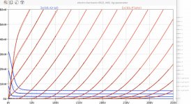
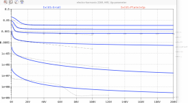
I just finished the 6922EH. This time, the grid current was a bit easier to mimic, except the posVg+lowVa-region.
In general, it seems to be pronounced for frame grid tubes that my generic i4-version delivers too high grid current for positive Vg and very low Va.
Fortunetly, this region is not of relevance for a HiFi Amp. It would be for a hard overdriven Guitar Amp, but for those, I have never seen any 6922 tubes used.")
best regards, Adrian
PS: Next tube will be the PC97!
I just finished the 6922EH. This time, the grid current was a bit easier to mimic, except the posVg+lowVa-region.
In general, it seems to be pronounced for frame grid tubes that my generic i4-version delivers too high grid current for positive Vg and very low Va.
Fortunetly, this region is not of relevance for a HiFi Amp. It would be for a hard overdriven Guitar Amp, but for those, I have never seen any 6922 tubes used.
best regards, Adrian
PS: Next tube will be the PC97!
Code:
*6922EH LTspice model based on the generic triode model from Adrian Immler, version i4
*A version log is at the end of this file
*100h BurnIn of 4 electro-harmonix factory tubes, sample selection and measurements done in April 2021
*Params fitted to the measured values by Adrian Immler, April 2021
*The high fit quality is presented at adrianimmler.simplesite.com
*History's best of tube decribing art (plus some new ideas) is merged to this new approach.
*@ neg. Vg, Ia accuracy is similar to Koren.
*@ small neg. Vg, the "Anlauf" current is considered.
*@ pos. Vg, Ig and Ia accuracy is on a unrivaled level.
*This offers new simulation possibilities like bias point setting with MOhm grid resistor,
*Audion radio circuits, low voltage amps, guitar distortion stages or pulsed stages.
*              i4 version
*              |  anode (plate)
*              |  | grid
*              |  | | cathode
*              |  | | |
.subckt 6922EH.i4 A G K
+ params:
*Parameters for the space charge current @ Vg <= 0
+ mu   = 32.8  ;Determines the voltage gain @ constant Ia
+ rad  = 1k8   ;Differential anode resistance, set @ Iad and Vg=0V
+ Vct  = 0.75  ;Offsets the Ia-traces on the Va axis. Electrode material's contact potential
+ kp   = 320   ;Mimics the island effect
+ xs   = 1.35  ;Determines the curve of the Ia traces. Typically between 1.2 and 1.8
*
*Parameters for assigning the space charge current to Ia and Ig @ Vg > 0
+ kB   = 3     ;Describes how fast Ia drops to zero when Va approaches zero.
+ radl = 350   ;Differential resistance for the Ia emission limit @ very small Va and Vg > 0
+ tsh  = 5     ;Ia transmission sharpness from 1th to 2nd Ia area. Keep between 3 and 20. Start with 20.
+ xl   = 1.2   ;Exponent for the emission limit
*
*Parameters of the grid-cathode vacuum diode
+ kvdg  = 28   ;virtual vacuumdiode. Causes an Ia reduction @ Ig > 0.
+ kg = 750     ;Inverse scaling factor for the Va independent part of Ig (caution - interacts with xg!)
+ Vctg = 0.05  ;Offsets the log Ig-traces on the Vg axis. Electrode material's contact potential
+ xg   = 1.25  ;Determines the curve of the Ig slope versus (positive) Vg and Va >> 0
+ VT   = 0.148 ;Log(Ig) slope @ Vg<0. VT=k/q*Tk (cathodes absolute temp, typically 1150K)
+ kVT=80m      ;Va dependant koeff. of VT
+ Vft2 = 0.75V gft2 = 5;finetunes the gridcurrent @ low Va and Vg near zero
*
*Parameters for the caps
+ cag  = 1p5   ;From datasheet
+ cak  = 2p0   ;From datasheet
+ cgk  = 3p25  ;From datasheet (actually the 6922EH datasheet says 32p5 which cannot be. A tipo is assumed)
*
*special purpose parameters
+ os = 1       ;Overall scaling factor, if a user wishes to simulate manufacturing tolerances
*
*Calculated parameters
+ Iad = {100/rad} ;Ia where the anode a.c. resistance is set according to rad.
+ ks = {pow(mu/(rad*xs*Iad**(1-1/xs)),-xs)} ;Reduces the unwished xs influence to the Ia slope
+ ksnom = {pow(mu/(rad*1.5*Iad**(1-1/1.5)),-1.5)} ;Sub-equation for calculating Vg0
+ Vg0 = {Vct + (Iad*ks)**(1/xs) - (Iad*ksnom)**(2/3)} ;Reduces the xs influence to Vct.
+ kl = {pow(1/(radl*xl*Ild**(1-1/xl)),-xl)} ;Reduces the xl influence to the Ia slope @ small Va
+ Ild = {sqrt(radl)*1m} ;Current where the Il a.c. resistance is set according to radl.
*
*Space charge current model
Bggi GGi 0 V=v(Gi,K)+Vg0 ;Effective internal grid voltage.
Bahc Ahc 0 V=uramp(v(A,K)) ;Anode voltage, hard cut to zero @ neg. value
Bst   St 0 V=uramp(max(v(GGi)+v(A,K)/(mu), v(A,K)/kp*ln(1+exp(kp*(1/mu+v(GGi)/(1+v(Ahc)))))));Steering volt.
Bs    Ai K I=os/ks*pow(v(St),xs) ;Langmuir-Childs law for the space charge current Is
*
*Anode current limit @ small Va
.func smin(z,y,k) {pow(pow(z+1f, -k)+pow(y+1f, -k), -1/k)} ;Min-function with smooth trans.
Ra  A Ai 1
Bgl Gi A I=min(i(Ra)-smin(1/kl*pow(v(Ahc),xl),i(Ra),tsh),i(Bgvd)*exp(4*v(G,K))) ;Ia emission limit
*
*Grid model
Bvdg G Gi I=1/kvdg*pwrs(v(G,Gi),1.5) ;Reduces the internal effective grid voltage when Ig rises
Rgip G Gi 1G ;avoids some warnings
Cvdg G Gi 0p1;this small cap improves convergence
.func fVT() {VT*exp(-kVT*sqrt(v(A,K)))}
.func Ivd(Vvd, kvd, xvd, VTvd)  {if(Vvd < 3, 1/kvd*pow(VTvd*xvd*ln(1+exp(Vvd/VTvd/xvd)),xvd), 1/kvd*pow(Vvd, xvd))} ;Vacuum diode function
Bgvd Gi K I=Ivd(v(G,K) + Vctg, kg/os, xg, fVT())
.func ft2() {gft2*(1-tanh(3*(v(G,K)+Vft2)))} ;Finetuning-func. improves ig-fit @ Vg near -0.5V, low Va.
Bgr Gi Ai I=ivd(v(GGi),ks/os, xs, 0.8*VT)/(1+ft2()+kB*v(Ahc));Is reflection to grid when Va approaches zero
Bs0 Ai K  I=ivd(v(GGi),ks/os, xs, 0.8*VT)/(1+ft2()) - os/ks*pow(v(GGi),xs) ;Compensates neg Ia @ small Va and Vg near zero
*
*Caps
C1 A G {cag}
C2 A K {cak}
C3 G K {cgk}
.ends
*
*Version log
*i1 :Initial version
*i2 :Pin order changed to the more common order A G K (Thanks to Markus Gyger for his tip)
*i3 :bugfix of the Ivd-function: now also usable for larger Vvd
*i4: Rgi replaced by a virtual vacuum diode (better convergence). ft1 deleted (no longer needed)
;2 new prarams for Ig finetuning @ Va and Vg near zero. New overall skaling factor os for aging etc.
Attachments
Last edited:
Here are Ayumi models.
Pentode model:
Triode-connected model:
Pentode model:
Code:
*
* Generic pentode model: 6CB6
* Copyright 2003--2008 by Ayumi Nakabayashi, All rights reserved.
* Version 3.10, Generated on Sat Mar  8 22:39:37 2008
*            Plate
*            | Screen Grid
*            | |  Control Grid
*            | |  |  Cathode
*            | |  |  |
.SUBCKT 6CB6 A G2 G1 K
BGG   GG   0 V=V(G1,K)+0.7350712
BM1   M1   0 V=(0.031445788*(URAMP(V(G2,K))+1e-10))**-2.20504
BM2   M2   0 V=(0.40485393*(URAMP(V(GG)+URAMP(V(G2,K))/18.926098)))**3.70504
BP    P    0 V=0.0046867337*(URAMP(V(GG)+URAMP(V(G2,K))/46.747967))**1.5
BIK   IK   0 V=U(V(GG))*V(P)+(1-U(V(GG)))*0.010960467*V(M1)*V(M2)
BIG   IG   0 V=0.0023433669*URAMP(V(G1,K))**1.5*(URAMP(V(G1,K))/(URAMP(V(A,K))+URAMP(V(G1,K)))*1.2+0.4)
BIK2  IK2  0 V=V(IK,IG)*(1-0.4*(EXP(-URAMP(V(A,K))/URAMP(V(G2,K))*15)-EXP(-15)))
BIG2T IG2T 0 V=V(IK2)*(0.78046782*(1-URAMP(V(A,K))/(URAMP(V(A,K))+10))**1.5+0.21953218)
BIK3  IK3  0 V=V(IK2)*(URAMP(V(A,K))+21225)/(URAMP(V(G2,K))+21225)
BIK4  IK4  0 V=V(IK3)-URAMP(V(IK3)-(0.0024945513*(URAMP(V(A,K))+URAMP(URAMP(V(G2,K))-URAMP(V(A,K))))**1.5))
BIP   IP   0 V=URAMP(V(IK4,IG2T)-URAMP(V(IK4,IG2T)-(0.0024945513*URAMP(V(A,K))**1.5)))
BIAK  A    K I=V(IP)+1e-10*V(A,K)
BIG2  G2   K I=URAMP(V(IK4,IP))
BIGK  G1   K I=V(IG)
* CAPS
CGA   G1  A  0.02p
CGK   G1  K  3.9p
C12   G1  G2 2.6p
CAK   A   K  1.9p
.ENDS
Code:
*
* Generic triode model: 6CB6T
* Copyright 2003--2008 by Ayumi Nakabayashi, All rights reserved.
* Version 3.10, Generated on Sat Mar  8 22:39:37 2008
*             Plate
*             | Grid
*             | | Cathode
*             | | |
.SUBCKT 6CB6T A G K
BGG   GG   0 V=V(G,K)+0.7350712
BM1   M1   0 V=(0.031445788*(URAMP(V(A,K))+1e-10))**-2.20504
BM2   M2   0 V=(0.40485393*(URAMP(V(GG)+URAMP(V(A,K))/18.926098)+1e-10))**3.70504
BP    P    0 V=0.0046867337*(URAMP(V(GG)+URAMP(V(A,K))/46.747967)+1e-10)**1.5
BIK   IK   0 V=U(V(GG))*V(P)+(1-U(V(GG)))*0.010960467*V(M1)*V(M2)
BIG   IG   0 V=0.0023433669*URAMP(V(G,K))**1.5*(URAMP(V(G,K))/(URAMP(V(A,K))+URAMP(V(G,K)))*1.2+0.4)
BIAK  A    K I=URAMP(V(IK,IG)-URAMP(V(IK,IG)-(0.0024945513*URAMP(V(A,K))**1.5)))+1e-10*V(A,K)
BIGK  G    K I=V(IG)
* CAPS
CGA   G    A 2.6p
CGK   G    K 3.9p
CAK   A    K 1.9p
.ENDS
Last edited:
PC97 anybody? (...)
Hi Zonnebloem
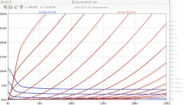
Here is your PC97 model, freshly baked!
A lot of "Mu-stretching" was needed to get it fitting the measured curves...
The 3 different brands a got (Siemens, Valvo, Telefunken) had all the identical construction - no differences visible. So I assume, all existing PC97 constructions are the same. Hence, no letters are needed in this model index to distinguish between manufacturers.
The curves from the Telefunken offered another contact voltage (a bit higher), which may indicate that Telefunken perhaps did a different grid coating (gold??). But it may be also just a sample variation.
all the best, Adrian
Code:
*PC97 LTspice model based on the generic triode model from Adrian Immler, version i4
*A version log is at the end of this file
*100h BurnIn of 4 Valvo, 1 Siemens and 1 Telefunken tubes, sample selection and measurements done in April 2021
*Params fitted to the measured values by Adrian Immler, April 2021
*The high fit quality is presented at adrianimmler.simplesite.com
*History's best of tube decribing art (plus some new ideas) is merged to this new approach.
*@ neg. Vg, Ia accuracy is similar to Koren.
*@ small neg. Vg, the "Anlauf" current is considered.
*@ pos. Vg, Ig and Ia accuracy is on a unrivaled level.
*This offers new simulation possibilities like bias point setting with MOhm grid resistor,
*Audion radio circuits, low voltage amps, guitar distortion stages or pulsed stages.
*            i4 version (Siemens, Telefunken and Valvo used the same construction. I assume also the others did so)
*            |  anode (plate)
*            |  | grid
*            |  | | cathode
*            |  | | |
.subckt PC97.i4 A G K
+ params:
*Parameters for the space charge current @ Vg <= 0
+ mu   = 110   ;Determines the voltage gain @ constant Ia
+ rad  = 4k35  ;Differential anode resistance, set @ Iad and Vg=0V
+ Vct  = 0.12  ;Offsets the Ia-traces on the Va axis. Electrode material's contact potential
+ kp   = 173   ;Mimics the island effect
+ xs   = 1.55  ;Determines the curve of the Ia traces. Typically between 1.2 and 1.8
*
*Parameters for assigning the space charge current to Ia and Ig @ Vg > 0
+ kB   = 0.6   ;Describes how fast Ia drops to zero when Va approaches zero.
+ radl = 680   ;Differential resistance for the Ia emission limit @ very small Va and Vg > 0
+ tsh  = 12    ;Ia transmission sharpness from 1th to 2nd Ia area. Keep between 3 and 20. Start with 20.
+ xl   = 1.3   ;Exponent for the emission limit
*
*Parameters of the grid-cathode vacuum diode
+ kvdg  = 93   ;virtual vacuumdiode. Causes an Ia reduction @ Ig > 0.
+ kg = 390     ;Inverse scaling factor for the Va independent part of Ig (caution - interacts with xg!)
+ Vctg = -0.25 ;Offsets the log Ig-traces on the Vg axis. Electrode material's contact potential
+ xg   = 1.25  ;Determines the curve of the Ig slope versus (positive) Vg and Va >> 0
+ VT   = 0.107 ;Log(Ig) slope @ Vg<0. VT=k/q*Tk (cathodes absolute temp, typically 1150K)
+ kVT=4m       ;Va dependant koeff. of VT
+ Vft2 = 0.25V gft2 = 3;finetunes the gridcurrent @ low Va and Vg near zero
*
*Parameters for the caps
+ cag  = 0p48  ;From Philips datasheet
+ cak  = 0p21  ;From Philips datasheet
+ cgk  = 3p2   ;From Philips datasheet
*
*special purpose parameters
+ os = 1       ;Overall scaling factor, if a user wishes to simulate manufacturing tolerances
*
*Calculated parameters
+ Iad = {100/rad} ;Ia where the anode a.c. resistance is set according to rad.
+ ks = {pow(mu/(rad*xs*Iad**(1-1/xs)),-xs)} ;Reduces the unwished xs influence to the Ia slope
+ ksnom = {pow(mu/(rad*1.5*Iad**(1-1/1.5)),-1.5)} ;Sub-equation for calculating Vg0
+ Vg0 = {Vct + (Iad*ks)**(1/xs) - (Iad*ksnom)**(2/3)} ;Reduces the xs influence to Vct.
+ kl = {pow(1/(radl*xl*Ild**(1-1/xl)),-xl)} ;Reduces the xl influence to the Ia slope @ small Va
+ Ild = {sqrt(radl)*1m} ;Current where the Il a.c. resistance is set according to radl.
*
*Space charge current model
Bggi GGi 0 V=v(Gi,K)+Vg0 ;Effective internal grid voltage.
Bahc Ahc 0 V=uramp(v(A,K)) ;Anode voltage, hard cut to zero @ neg. value
Bst   St 0 V=uramp(max(v(GGi)+v(A,K)/(mu), v(A,K)/kp*ln(1+exp(kp*(1/mu+v(GGi)/(1+v(Ahc)))))));Steering volt.
Bs    Ai K I=os/ks*pow(v(St),xs) ;Langmuir-Childs law for the space charge current Is
*
*Anode current limit @ small Va
.func smin(z,y,k) {pow(pow(z+1f, -k)+pow(y+1f, -k), -1/k)} ;Min-function with smooth trans.
Ra  A Ai 1
Bgl Gi A I=min(i(Ra)-smin(1/kl*pow(v(Ahc),xl),i(Ra),tsh),i(Bgvd)*exp(4*v(G,K))) ;Ia emission limit
*
*Grid model
Bvdg G Gi I=1/kvdg*pwrs(v(G,Gi),1.5) ;Reduces the internal effective grid voltage when Ig rises
Rgip G Gi 1G ;avoids some warnings
Cvdg G Gi 0p1;this small cap improves convergence
.func fVT() {VT*exp(-kVT*sqrt(v(A,K)))}
.func Ivd(Vvd, kvd, xvd, VTvd)  {if(Vvd < 3, 1/kvd*pow(VTvd*xvd*ln(1+exp(Vvd/VTvd/xvd)),xvd), 1/kvd*pow(Vvd, xvd))} ;Vacuum diode function
Bgvd Gi K I=Ivd(v(G,K) + Vctg, kg/os, xg, fVT())
.func ft2() {gft2*(1-tanh(3*(v(G,K)+Vft2)))} ;Finetuning-func. improves ig-fit @ Vg near -0.5V, low Va.
Bgr Gi Ai I=ivd(v(GGi),ks/os, xs, 0.8*VT)/(1+ft2()+kB*v(Ahc));Is reflection to grid when Va approaches zero
Bs0 Ai K  I=ivd(v(GGi),ks/os, xs, 0.8*VT)/(1+ft2()) - os/ks*pow(v(GGi),xs) ;Compensates neg Ia @ small Va and Vg near zero
*
*Caps
C1 A G {cag}
C2 A K {cak}
C3 G K {cgk}
.ends
*
*Version log
*i1 :Initial version
*i2 :Pin order changed to the more common order A G K (Thanks to Markus Gyger for his tip)
*i3 :bugfix of the Ivd-function: now also usable for larger Vvd
*i4: Rgi replaced by a virtual vacuum diode (better convergence). ft1 deleted (no longer needed)
;2 new prarams for Ig finetuning @ Va and Vg near zero. New overall skaling factor os for aging etc.
Attachments
"mu-stretching"
I like it!
MerlinB used that triode in an RIAA preamp design (in his tube preamps book). He mentioned that it's not very linear. I think he said something like 'verging on variable-mu'.
I wonder how different the many other similar RF triodes are, like 6HQ5, 6HM5, 6HA5, PC900, and so on? They all look very similar in their data sheets.
Thanks for this PC967 model, and for the 6922 models. This is great stuff!
--
I gave the PC97 model a quick spin. Works great!
One thing I noticed is that I get less gain out of it than I get from some 6HM5 and 6HQ5 models I have from previous generous contributors.
Do you know if PC97 is supposed to have lower mu than 6HM5, 6HQ5, 6HA5? Or is that a function of the chosen model?
--
One thing I noticed is that I get less gain out of it than I get from some 6HM5 and 6HQ5 models I have from previous generous contributors.
Do you know if PC97 is supposed to have lower mu than 6HM5, 6HQ5, 6HA5? Or is that a function of the chosen model?
--
Hi Rongon
I'm glad to hear that my PC97 model works fine!
According to its datasheet, the gain is a bit lower (mu=65) compared to the 6HM5 (Mu=72).
It also depends on the working point. The PC97 has a very dominant island effect. Hence, if your working point needs a large negative grid voltage (-1.5V or less), the gain is further reduced due to island effect.
best regards, Adrian
Thanks Adrian. That all makes sense.
I wonder...
Do you think a 'low' grid bias of only -1.2V would induce a lot of grid current from these tubes? I think they were actually designed to work with that kind of a grid bias voltage, but I'm not sure. The model seems to think -1.2V works fine, but you know, real life can be different.
Or is it better to design for -1.7V or thereabouts with this kind of frame grid RF triode, to inhibit any possibility of excessive grid current?
I'm thinking of using this type of tube as the first stage in a phono preamp (after a design by MerlinB), so I wouldn't want to be injecting current into the phono cartridge's coils...
--
Hi rongon,
Which brand do you intend to use?
5 of 6 from my measured samples stayed well below 20nA @ Vg=-1V, exept one (the Telefunken when I remeber right), which also had its gm out of range of the others.
But that one may also be a "monday morning sample" - difficult to say.
Which brand do you intend to use?
5 of 6 from my measured samples stayed well below 20nA @ Vg=-1V, exept one (the Telefunken when I remeber right), which also had its gm out of range of the others.
But that one may also be a "monday morning sample" - difficult to say.
... ooops, I mixed up the Telefunken and the Siemens tube. Telefunken is behaving like the Valvos (on which my model is based on).
Siemens showes higher gm and higher grid current. But as mentioned, I have just 1 Siemens sample, so I do not know whether it is caused by different grid or by manufacturing tolerances.
I would not dare to go with -1.2V. -1.7V is for sure ok.
Siemens showes higher gm and higher grid current. But as mentioned, I have just 1 Siemens sample, so I do not know whether it is caused by different grid or by manufacturing tolerances.
I would not dare to go with -1.2V. -1.7V is for sure ok.
Attachments
Last edited:
- Home
- Amplifiers
- Tubes / Valves
- Vacuum Tube SPICE Models