.option noopiter
.options GminSteps=0
.options SrcSteps=0
LTSpice does not guarantee that a particular iteration will be good even it succeeded in finding the operating point. The above one or more options can be used. I try to disable first option and it works. Check log for error info.
.options GminSteps=0
.options SrcSteps=0
LTSpice does not guarantee that a particular iteration will be good even it succeeded in finding the operating point. The above one or more options can be used. I try to disable first option and it works. Check log for error info.
Hi, I've used the following LTSpice models:
...but results are not good on simulations.
I attach the LTSpice asc file to make everyone able to find a solution.
Code:
*-----------------------------------------------------------------------
* Filename:		6kg6.inc  V2 12/10/97
* Simulator:		PSpice
* Device type:		Power pentode
* Device model:		6KG6/EL509
*			(also 40KG6/PL509 as no heater model)
*
* Author:		Duncan Munro
* Date:			21/7/97
* Copyright:		(C)1997-2000 Duncan Amplification
*
*
* V2 [12/10/97]: Screen current limited to prevent screen current
*		 draw at Vs = 0.
*
* The following parameters are not modelled:
*
*   (1) Heater
*   (2) Grid current is an approximation in the absence
*       of suitable data
*
* Also see comments below, as the Svetlana EL509 is of different
* construction and has different capacitances.
*
* Please note that this model is provided "as is" and
* no warranty is provided in respect of its suitability
* for any application.
*
* This model is provided for educational and non-profit use.
*
* Email queries to [email]postmaster@duncanamps.com[/email]
*
* Pins   A  Anode
*        S  Screen
*        G  Grid
*        K  Cathode
*
*-----------------------------------------------------------------------

.SUBCKT 6KG6 A S G K
*
* Calculate contribution to cathode current
*
Eat	at	0	VALUE={0.636*ATAN(V(A,K)/20)}
Eme	me	0	VALUE={PWR(LIMIT{V(A,K),0,10000},1.5)/17}
Emu	mu	0	VALUE={PWRS(V(G,K),1-(LIMIT{-V(G,K),5,9999}-5)/1150)}
Egs	gs	0	VALUE={LIMIT{V(S,K)/19+V(mu)/4.3+V(A,K)/800,0,1E6}}
Egs2	gs2	0	VALUE={PWRS(V(gs),1.5)}
Ecath  	cc    	0 	VALUE={LIMIT{V(gs2)*V(at),0,V(me)}}
Elim	el	0	VALUE={LIMIT{V(gs2)*V(at)-V(cc),0,99999}}
*
* Calculate anode current
*
Ga     	A     	K     	VALUE={6E-2*V(cc)}
*
* Calculate screen current
*
Escrn	sc	0	VALUE={V(gs2)*(1.1-V(at))+1.2*V(el)}
Gs     	S     	K	VALUE={1.2E-2*V(sc)*LIMIT{V(S,K),0,10}/10}
*
* Grid current (approximation - does not model low va/vs)
*
Gg	G	K	VALUE={PWR(LIMIT{V(G,K)+1,0,1E6},1.5)*50E-6}
*
* Capacitances
* NOTE: Change Cg1 from 37p to 25p for Svetlana EL509
*
Cg1	G	K	37p
Cak	A	K	18.5p
Cg1a	G	A	2.5p

.ENDS
Code:
*ECC81 LTspice model based on the generic triode model from Adrian Immler, version i4
*A version log is at the end of this file
*100h BurnIn of 8 RFT tubes, sample selection and measurements done in Febr. 2020
*Params fitted to the measured values by Adrian Immler, Febr. 2020
*The high fit quality is presented at adrianimmler.simplesite.com
*History's best of tube decribing art (plus some new ideas) is merged to this new approach.
*@ neg. Vg, Ia accuracy is similar to Koren or Ayumi models.
*@ small neg. Vg, the "Anlauf" current is considered.
*@ pos. Vg, Ig and Ia accuracy is on a unrivaled level.
*This offers new simulation possibilities like bias point setting with MOhm grid resistor,
*Audion radio circuits, low voltage amps, guitar distortion stages or pulsed stages.
*                  anode (plate)
*                  | grid
*                  | | cathode
*                  | | |
.subckt ECC81.RFi4 A G K
.params
*Parameters for the space charge current @ Vg <= 0
+ mu   = 68   ;Determines the voltage gain @ constant Ia
+ rad  = 9k5  ;Differential anode resistance, set @ Iad and Vg=0V
+ Vct  = 0.28 ;Offsets the Ia-traces on the Va axis. Electrode material's contact potential
+ kp   = 240  ;Mimics the island effect
+ xs   = 1.4  ;Determines the curve of the Ia traces. Typically between 1.2 and 1.8
*
*Parameters for assigning the space charge current to Ia and Ig @ Vg > 0
+ kB   = 0.22 ;Describes how fast Ia drops to zero when Va approaches zero.
+ radl = 520  ;Differential resistance for the Ia emission limit @ very small Va and Vg > 0
+ tsh  = 10   ;Ia transmission sharpness from 1th to 2nd Ia area. Keep between 3 and 20. Start with 20.
+ xl   = 1.3  ;Exponent for the emission limit
*
*Parameters of the grid-cathode vacuum diode
+ kvdg  = 63  ;virtual vacuumdiode. Causes an Ia reduction @ Ig > 0.
+ kg = 840    ;Inverse scaling factor for the Va independent part of Ig (caution - interacts with xg!)
+ Vctg = 0.1    ;Offsets the log Ig-traces on the Vg axis. Electrode material's contact potential
+ xg   = 1.5  ;Determines the curve of the Ig slope versus (positive) Vg and Va >> 0
+ VT   = 0.165 ;Log(Ig) slope @ Vg<0. VT=k/q*Tk (cathodes absolute temp, typically 1150K)
+ kVT=35m ;Va dependant koeff. of VT
+ Vft2 = 0.6 gft2 = 7  ;finetunes the gridcurrent @ low Va and Vg near zero
*
*Parameters for the caps
+ cag  = 1p6  ;From datasheet ("transfer cap.")
+ cak  = 0p2  ;From datasheet ("output cap.")
+ cgk  = 2p3  ;From datasheet.("input cap")
*
*special purpose parameters
+ os = 1      ;Overall scaling factor, if a user wishes to simulate manufacturing tolerances
*
*Calculated parameters
+ Iad = 100/rad  ;Ia where the anode a.c. resistance is set according to rad.
+ ks = pow(mu/(rad*xs*Iad**(1-1/xs)),-xs) ;Reduces the unwished xs influence to the Ia slope
+ ksnom = pow(mu/(rad*1.5*Iad**(1-1/1.5)),-1.5) ;Sub-equation for calculating Vg0
+ Vg0 = Vct + (Iad*ks)**(1/xs) - (Iad*ksnom)**(2/3) ;Reduces the xs influence to Vct.
+ kl = pow(1/(radl*xl*Ild**(1-1/xl)),-xl) ;Reduces the xl influence to the Ia slope @ small Va
+ Ild = sqrt(radl)*1m ;Current where the Il a.c. resistance is set according to radl.
*
*Space charge current model
Bggi GGi 0 V=v(Gi,K)+Vg0 ;Effective internal grid voltage.
Bahc Ahc 0 V=uramp(v(A,K)) ;Anode voltage, hard cut to zero @ neg. value
Bst   St 0 V=uramp(max(v(GGi)+v(A,K)/(mu), v(A,K)/kp*ln(1+exp(kp*(1/mu+v(GGi)/(1+v(Ahc)))))));Steering volt.
Bs    Ai K I=os/ks*pow(v(St),xs) ;Langmuir-Childs law for the space charge current Is
*
*Anode current limit @ small Va
.func smin(z,y,k) {pow(pow(z+1f, -k)+pow(y+1f, -k), -1/k)} ;Min-function with smooth trans.
Ra  A Ai 1
Bgl Gi A I=min(i(Ra)-smin(1/kl*pow(v(Ahc),xl),i(Ra),tsh),i(Bgvd)*exp(4*v(G,K))) ;Ia emission limit
*
*Grid model
Bvdg G Gi I=1/kvdg*pwrs(v(G,Gi),1.5) ;Reduces the internal effective grid voltage when Ig rises
Rgip G Gi 1G ;avoids some warnings
.func fVT() {VT*exp(-kVT*sqrt(v(A,K)))}
.func Ivd(Vvd, kvd, xvd, VTvd)  {if(Vvd < 3, 1/kvd*pow(VTvd*xvd*ln(1+exp(Vvd/VTvd/xvd)),xvd), 1/kvd*pow(Vvd, xvd))} ;Vacuum diode function
*Bgvd Gi K I=Ivd(v(G,K) + Vctg - uramp(-v(A,K)/mu), kg/os, xg, VT)
Bgvd Gi K I=Ivd(v(G,K) + Vctg, kg/os, xg, fVT())
.func ft2() {gft2*(1-tanh(3*(v(G,K)+Vft2)))} ;Finetuning-func. improves ig-fit @ Vg near -0.5V, low Va.
Bgr Gi Ai I=ivd(v(GGi),ks/os, xs, 0.8*fVT())/(1+ft2()+kB*v(Ahc));Is reflection to grid when Va approaches zero
Bs0 Ai K  I=ivd(v(GGi),ks/os, xs, 0.8*fVT())/(1+ft2()) - os/ks*pow(v(GGi),xs) ;Compensates neg Ia @ small Va and Vg near zero
*
*Caps
C1 A G {cag}
C2 A K {cak}
C3 G K {cgk}
.end
*
*Version log
*i1 :Initial version
*i2 :Pin order changed to the more common order „A G K“ (Thanks to Markus Gyger for his tip)
*i3 :bugfix of the Ivd-function: now also usable for larger Vvd
*i4: Rgi replaced by a virtual vacuum diode (better convergence). ft1 deleted (no longer needed)
;2 new prarams for Ig finetuning @ Va and Vg near zero. New emission skaling factor ke for aging etc.
Code:
*
* Generic triode model: ECC99_AN
* Copyright 2003--2008 by Ayumi Nakabayashi, All rights reserved.
* Version 3.10, Generated on Sun Jan 12 18:46:10 2014
*                Plate
*                | Grid
*                | | Cathode
*                | | |
.SUBCKT ECC99_AN A G K
BGG   GG   0 V=V(G,K)+0.042958289
BM1   M1   0 V=(0.02038404*(URAMP(V(A,K))+1e-10))**-0.86570009
BM2   M2   0 V=(0.63406177*(URAMP(V(GG)+URAMP(V(A,K))/17.952193)+1e-10))**2.3657001
BP    P    0 V=0.005978906*(URAMP(V(GG)+URAMP(V(A,K))/28.313003)+1e-10)**1.5
BIK   IK   0 V=U(V(GG))*V(P)+(1-U(V(GG)))*0.0037149974*V(M1)*V(M2)
BIG   IG   0 V=0.002989453*URAMP(V(G,K))**1.5*(URAMP(V(G,K))/(URAMP(V(A,K))+URAMP(V(G,K)))*1.2+0.4)
BIAK  A    K I=URAMP(V(IK,IG)-URAMP(V(IK,IG)-(0.0033089913*URAMP(V(A,K))**1.5)))+1e-10*V(A,K)
BIGK  G    K I=V(IG)
* CAPS
CGA   G    A 5.8p
CGK   G    K 5.1p
CAK   A    K 0.8p
.ENDS
...but results are not good on simulations.
I attach the LTSpice asc file to make everyone able to find a solution.
Attachments
Last edited:
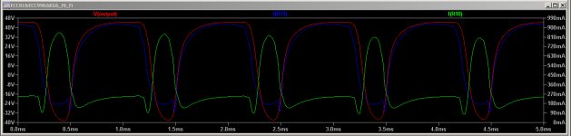
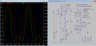
I made a few mods mainly to increase the coupling factor K from 0.9995 to 0.99995 to make the oscillation disappeared. In real amp the K factor is calculated from leakage inductance K=sqr((Lpri-Ll)/Lpri) where Lpri=primary inductance and Ll=leakage inductance. Other mods are to make the PI output more symmetrical. From sim we see the bottom cathode tubes current waveform is not straight (hump) indicated cutoff has ringing, may to increase grid bias to increase overlapping region or increase the driver current. Also the series resistance of OT should be adjusted.
Attachments
Last edited:
I do aspologize with everyone, I posted that simulation in the wrong topic, it was supposed to be here: Special offer for skilled tube fanatics
Thank you Koonw for correcting some issues, I really appreciate and I quoted your contribution in the original thread.
Thank you Koonw for correcting some issues, I really appreciate and I quoted your contribution in the original thread.
Last edited:
Hi,
I am looking for a *.lib and *.asy file for 6V6 and 5GZ4 tube. Does anybody could help me with that?
Most "pentode" SPICE models are actually tetrode models, as the suppressor grid is usually not included in the model. LTspice has a built-in tetrode symbol in its Misc folder so you don't need a special symbol for them. Don't use the built-in pentode symbol; it does have a pin assignment for the suppressor grid so it will not work with most "pentode" (actually tetrode) SPICE models.
Here is the Ayumi pentode model for the 6V6:
Code:
*
*
* Generic pentode model: 6V6
* Copyright 2003--2008 by Ayumi Nakabayashi, All rights reserved.
* Version 3.10, Generated on Sat Mar  8 22:41:04 2008
*           Plate
*           | Screen Grid
*           | |  Control Grid
*           | |  |  Cathode
*           | |  |  |
.SUBCKT 6V6 A G2 G1 K
BGG   GG   0 V=V(G1,K)+0.99999998
BM1   M1   0 V=(0.048335289*(URAMP(V(G2,K))+1e-10))**-0.77023894
BM2   M2   0 V=(0.6607234*(URAMP(V(GG)+URAMP(V(G2,K))/7.0192317)))**2.2702389
BP    P    0 V=0.0010053341*(URAMP(V(GG)+URAMP(V(G2,K))/10.623555))**1.5
BIK   IK   0 V=U(V(GG))*V(P)+(1-U(V(GG)))*0.00060166202*V(M1)*V(M2)
BIG   IG   0 V=0.00051429562*URAMP(V(G1,K))**1.5*(URAMP(V(G1,K))/(URAMP(V(A,K))+URAMP(V(G1,K)))*1.2+0.4)
BIK2  IK2  0 V=V(IK,IG)*(1-0.4*(EXP(-URAMP(V(A,K))/URAMP(V(G2,K))*15)-EXP(-15)))
BIG2T IG2T 0 V=V(IK2)*(0.916000233*(1-URAMP(V(A,K))/(URAMP(V(A,K))+10))**1.5+0.083999767)
BIK3  IK3  0 V=V(IK2)*(URAMP(V(A,K))+3125)/(URAMP(V(G2,K))+3125)
BIK4  IK4  0 V=V(IK3)-URAMP(V(IK3)-(0.00061491868*(URAMP(V(A,K))+URAMP(URAMP(V(G2,K))-URAMP(V(A,K))))**1.5))
BIP   IP   0 V=URAMP(V(IK4,IG2T)-URAMP(V(IK4,IG2T)-(0.00061491868*URAMP(V(A,K))**1.5)))
BIAK  A    K I=V(IP)+1e-10*V(A,K)
BIG2  G2   K I=URAMP(V(IK4,IP))
BIGK  G1   K I=V(IG)
* CAPS
CGA   G1  A  0.7p
CGK   G1  K  5p
C12   G1  G2 3.3p
CAK   A   K  6.9p
.ENDS
Last edited:
E81L triode model:
Code:
* Plate Curves image file: E81L-T.png
 * Data source link:
*----------------------------------------------------------------------------------
.SUBCKT TRIODE_E81L_T 1 2 3 ; Plate Grid Cathode
+ PARAMS: CCG=11.2P  CGP=0.02P CCP=6.5P
+ MU=36 KG1=285 KP=252 KVB=156 VCT=-0.3 EX=1.358
+ VGOFF=-0.6 IGA=7.1E-4 IGB=0.225 IGC=8 IGEX=1.76
* Vp_MAX=300 Ip_MAX=40 Vg_step=1 Vg_start=0 Vg_count=7
* Rp=4000 Vg_ac=55 P_max=5.6 Vg_qui=-48 Vp_qui=300
* X_MIN=44 Y_MIN=30 X_SIZE=813 Y_SIZE=542 FSZ_X=1296 FSZ_Y=736 XYGrid=false
* showLoadLine=n showIp=y isDHT=n isPP=n isAsymPP=n showDissipLimit=y
* showIg1=y gridLevel2=y isInputSnapped=n
* XYProjections=n harmonicPlot=n dissipPlot=n
*----------------------------------------------------------------------------------
E1 7 0 VALUE={V(1,3)/KP*LOG(1+EXP(KP*(1/MU+(VCT+V(2,3))/SQRT(KVB+V(1,3)*V(1,3)))))}
RE1 7 0 1G  ; TO AVOID FLOATING NODES
G1 1 3 VALUE={(PWR(V(7),EX)+PWRS(V(7),EX))/KG1}
RCP 1 3 1G   ; TO AVOID FLOATING NODES
C1 2 3 {CCG} ; CATHODE-GRID
C2 2 1 {CGP} ; GRID=PLATE
C3 1 3 {CCP} ; CATHODE-PLATE
RE2 2 0 1G
EGC 8 0 VALUE={V(2,3)-VGOFF} ; POSITIVE GRID THRESHOLD
GG 2 3 VALUE={(IGA+IGB/(IGC+V(1,3)))*(MU/KG1)*(PWR(V(8),IGEX)+PWRS(V(8),IGEX))}
.ENDS
*$
Attachments
EL152 (similar to LS-50/GU-50) pentode and triode models:
EL152 Pentode Spice Model – Bartola(R) Valves
Cheers
Ale
EL152 Pentode Spice Model – Bartola(R) Valves
Cheers
Ale
Hi Ale,
Do you happen to have models for the 7199 (both pentode and triode sections)? I've tried various models in the past but none produce reasonable results in the Dynaco amplifier circuit. I realize that this tube is essentially obsolete but I'm still interested in models mostly for academic reasons.
Thanks.
Thanks, Ale. Maybe someone can produce models from the published curves:
https://frank.pocnet.net/sheets/168/7/7199.pdf
https://frank.pocnet.net/sheets/168/7/7199.pdf
- Home
- Amplifiers
- Tubes / Valves
- Vacuum Tube SPICE Models