The pentode parameters are covered here: Improved vacuum tube models for SPICE, Part 1. And the only way to generate the Derk models is by actually tracing the tubes using uTracer.
Perfect, thank you verry much
Ayumi vs. (modified) Koren model for power pentodes
Hello,
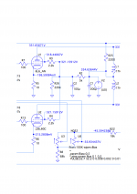
in the example below You see a stage with two 6L6GC in push pull. The upper tube is modeled using the Ayumi model, the lower tube is done using a Koren model modified with µ-Tracer data. Only .OP analysis is done. Please note the voltage directly at G2: at least in the .OP simulation there is obviously no G2 current or an extremely small one with the Koren type model.
The .TRAN simulation does, however, show at least roughly plausible values of G2 if You check them with .MEAS commands.
So far, so good. Unfortunately the Ayumi models are computionally extremely expensive and can therefore not be used in general design work, but just "as the last step".
So there is the question if there exist other computationally lightweight models which come a bit closer to reality than the (otherwise useful) Koren models?
Hello,
in the example below You see a stage with two 6L6GC in push pull. The upper tube is modeled using the Ayumi model, the lower tube is done using a Koren model modified with µ-Tracer data. Only .OP analysis is done. Please note the voltage directly at G2: at least in the .OP simulation there is obviously no G2 current or an extremely small one with the Koren type model.
The .TRAN simulation does, however, show at least roughly plausible values of G2 if You check them with .MEAS commands.
So far, so good. Unfortunately the Ayumi models are computionally extremely expensive and can therefore not be used in general design work, but just "as the last step".
So there is the question if there exist other computationally lightweight models which come a bit closer to reality than the (otherwise useful) Koren models?
Attachments
Why is that the case? Many members have used the Ayumi pentode models without issue, and would find your experience quite perplexing...Unfortunately the Ayumi models are computionally extremely expensive and can therefore not be used in general design work, but just "as the last step".
Hi Bea
Nice to meet you again, for this time on the diyaudio site ;-)
You now, Norman Koren did not spent much effort to model accurate grid currents...
Why not try the Duncan Munro model? It is also fast (as it was also developed in the past century with its slow clocked computers), and (more or less) accurate grid currents was a high priority goal for Duncan.
Pentodes
all the best, Adrian
P.S: Be aware that the Ayumi models deliver a better overall fit quality!
Hello Adrian,
thanks! Of course i am aware that the Ayumi models are good fit quality. But the can be annoying, especially if You want to do fine tuning by trial and error. (And i've observed occasional convergence problems using the Derk models i have also tried out.) BTW
thanks! Of course i am aware that the Ayumi models are good fit quality. But the can be annoying, especially if You want to do fine tuning by trial and error. (And i've observed occasional convergence problems using the Derk models i have also tried out.) BTW
Hi Bea
Occasional convergence problems of Derk models may have the root cause in the fact that they are able to mimic secondary emission effects. That means that there are probably negative differential resistances, introducing a risk for oscillations in real life or convergence problems in simulations.
Occasional convergence problems of Derk models may have the root cause in the fact that they are able to mimic secondary emission effects. That means that there are probably negative differential resistances, introducing a risk for oscillations in real life or convergence problems in simulations.
... Unfortunately the Ayumi models are computionally extremely expensive and can therefore not be used in general design work ...
never experienced anything like taking minutes ... not even with my oldest Pentium 4 2GHz single core and even less so with modern 8-core 4-GHz hardware;
anyway, could it be that you use .step commands in your "general design work", maybe multiple nested ones ?
if you could post a complete .asc file (without your secret ingrediences of course) including model file we could try to douplicate your results and find a way to tune the LTSPICE setup
6FM7 compactron with two dissimilar triodes
#1: small signal mu=66
#2: vertical output 10W plate
can't find any Spice models anywhere ... appreciate volunteer with the necessary tools
here's datasheet: http://frank.yueksel.org/sheets/123/6/6FM7.pdf
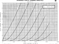
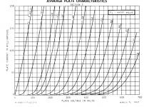
curves attached (attention, there is an awkward intermediate at -25v in the 2nd)
#1: small signal mu=66
#2: vertical output 10W plate
can't find any Spice models anywhere ... appreciate volunteer with the necessary tools
here's datasheet: http://frank.yueksel.org/sheets/123/6/6FM7.pdf
curves attached (attention, there is an awkward intermediate at -25v in the 2nd)
Attachments
Last edited:
Hi Sorento
You will find the 6FM7 (section1) spice model on my website:
http://adrianimmler.simplesite.com/440956786
Same to the graphs, showing the achieved fit quality.
PS: The datasheet does not contain any grid current traces for the section 2 triode, so I decided to not fit this section (as I don't want to provide a model with perhaps "wrong" Ig behavior)
PPS: Please note that the grid current scale is different to the the anode current scale. I managed that by multiplying the grid current by 0.8 in the LTspice graph.
kind regards, Adrian
6FM7 SPICE Models
6FM7 (Section 1):
6FM7 (Section 2):
6FM7 (Section 1):
Code:
*
* Generic triode model: 6FM7_T1_AN
* Copyright 2003--2008 by Ayumi Nakabayashi, All rights reserved.
* Version 3.10, Generated on Tue Jan 29 11:36:34 2019
*                  Anode
*                  | Grid
*                  | | Cathode
*                  | | |
.SUBCKT 6FM7_T1_AN A G K
BGG   GG   0 V=V(G,K)+0.43055578
BM1   M1   0 V=(0.0046490712*(URAMP(V(A,K))+1e-10))**-0.51982331
BM2   M2   0 V=(0.74263922*(URAMP(V(GG)+URAMP(V(A,K))/55.357463)+1e-10))**2.0198233
BP    P    0 V=0.0016884355*(URAMP(V(GG)+URAMP(V(A,K))/74.54153)+1e-10)**1.5
BIK   IK   0 V=U(V(GG))*V(P)+(1-U(V(GG)))*0.00097329237*V(M1)*V(M2)
BIG   IG   0 V=0.00084421773*URAMP(V(G,K))**1.5*(URAMP(V(G,K))/(URAMP(V(A,K))+URAMP(V(G,K)))*1.2+0.4)
BIAK  A    K I=URAMP(V(IK,IG)-URAMP(V(IK,IG)-(0.00087830783*URAMP(V(A,K))**1.5)))+1e-10*V(A,K)
BIGK  G    K I=V(IG)
* CAPS
CGA   G    A 4p
CGK   G    K 2.4p
CAK   A    K 0.4p
.ENDS
6FM7 (Section 2):
Code:
*
* Generic triode model: 6FM7_T2_AN
* Copyright 2003--2008 by Ayumi Nakabayashi, All rights reserved.
* Version 3.10, Generated on Tue Jan 29 11:37:44 2019
*                  Anode
*                  | Grid
*                  | | Cathode
*                  | | |
.SUBCKT 6FM7_T2_AN A G K
BGG   GG   0 V=V(G,K)+1
BM1   M1   0 V=(0.10600611*(URAMP(V(A,K))+1e-10))**-1.2768421
BM2   M2   0 V=(0.54018197*(URAMP(V(GG)+URAMP(V(A,K))/4.337656)+1e-10))**2.7768421
BP    P    0 V=0.0047855456*(URAMP(V(GG)+URAMP(V(A,K))/8.0299904)+1e-10)**1.5
BIK   IK   0 V=U(V(GG))*V(P)+(1-U(V(GG)))*0.00389593*V(M1)*V(M2)
BIG   IG   0 V=0.0023927728*URAMP(V(G,K))**1.5*(URAMP(V(G,K))/(URAMP(V(A,K))+URAMP(V(G,K)))*1.2+0.4)
BIAK  A    K I=URAMP(V(IK,IG)-URAMP(V(IK,IG)-(0.0033139904*URAMP(V(A,K))**1.5)))+1e-10*V(A,K)
BIGK  G    K I=V(IG)
* CAPS
CGA   G    A 7p
CGK   G    K 7p
CAK   A    K 1.1p
.ENDS6FM7 (Section 1):
* Generic triode model: 6FM7_T1_AN
6FM7 (Section 2):
* Generic triode model: 6FM7_T2_AN
* Copyright 2003--2008 by Ayumi Nakabayashi, All rights reserved.
[/code]
! excellent ! many thanks !
Hi indra1,
Koonw has already fitted this tube, please see his reply #1405
Hi all
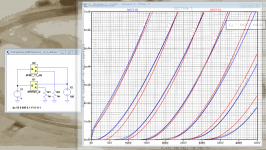
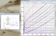
As we have now tow different 6FM7#1 approaches made from the same datasheet, it is a good occasion to compare to see where their strengths/weaknesses are.
calculation performance:
6FM7#1_i2: 8.85s for 585k working point calculations
6FM7_T1_AN: 6.64s for 585k working point calculations
=> winner is 6FM7_T1_AN
accuracy:
see attached images
=> winner is 6FM7#1_i2 (especially for pos. Vg)
all the best, Adrian
Comparison 6FM7#1 i2 vs AN negVg.PNG
Comparison 6FM7#1 i2 vs AN posVg.PNG
Koonw has already fitted this tube, please see his reply #1405
Hi all
As we have now tow different 6FM7#1 approaches made from the same datasheet, it is a good occasion to compare to see where their strengths/weaknesses are.
calculation performance:
6FM7#1_i2: 8.85s for 585k working point calculations
6FM7_T1_AN: 6.64s for 585k working point calculations
=> winner is 6FM7_T1_AN
accuracy:
see attached images
=> winner is 6FM7#1_i2 (especially for pos. Vg)
all the best, Adrian
Comparison 6FM7#1 i2 vs AN negVg.PNG
Comparison 6FM7#1 i2 vs AN posVg.PNG
Attachments

Anybody has the pentode or triode ltspice model for PL83 or any of identical valves (EL83, 15A6, 6CK6 or CV2726)? I check the archive and there arent any models there.
PL 83, Tube PL83; Rohre PL 83 ID3372, Vacuum Pentode
PL 83, Tube PL83; Rohre PL 83 ID3372, Vacuum Pentode
- Home
- Amplifiers
- Tubes / Valves
- Vacuum Tube SPICE Models