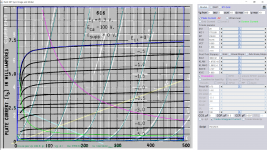
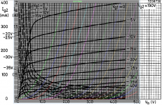
* Plate Curves image file: 1z24b.gif
Here is the model, fill in the capacitances:
*$[/CODE]
Oh, excellent, Koonw. Thank you so much.
Does anyone have or know of a good 6C6 model? I would have thought that would be covered already, but a search of this forum plus the web in general has turned up nothing.
I've got a good model of 6SJ7, which is part of the same family and looks nearly identical on paper, but not sure if it's close enough to use as an even substitute.
I've got a good model of 6SJ7, which is part of the same family and looks nearly identical on paper, but not sure if it's close enough to use as an even substitute.
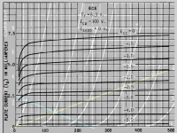
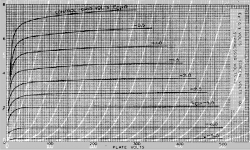
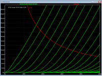
There is 6c6 triode connected curve and schematic here.
Code:
**** 6C6P_TS ******************************************
* Created on 01/03/2019 10:27 using paint_kip.jar
* [URL="http://www.dmitrynizh.com/tubeparams_image.htm"]Model Paint Tools: Trace Tube Parameters over Plate Curves, Interactively[/URL]
* Plate Curves image file: 6c6p_ts.png
* Data source link: <plate curves URL>
*----------------------------------------------------------------------------------
.SUBCKT 6C6_TS P G2 G K ; LTSpice tetrode.asy pinout
* .SUBCKT 6C6_TS P G K G2 ; Koren Pentode Pspice pinout
+ PARAMS: MU=20 KG1=7753.68 KP=238.93 KVB=64.76 VCT=0.565 EX=1.666 KG2=3862.32 KNEE=4.147 KVC=1.603
+ KLAM=1.875E-10 KLAMG=1.081E-4   KNK=-0.044 KNG=0.006 KNPL=50 KNSL=11 KNPR=120 KNSR=29
+ CCG=5P CGP=6.5P CCP=0.007P RGI=2000.0
* Vp_MAX=500 Ip_MAX=10 Vg_step=5 Vg_start=0 Vg_count=10
* X_MIN=98 Y_MIN=18 X_SIZE=960 Y_SIZE=770 FSZ_X=1550 FSZ_Y=878 XYGrid=false
* Rp=1400 Vg_ac=20 P_max=0.75 Vg_qui=-22.5 Vp_qui=300
* showLoadLine=n showIp=y isDHP=n isPP=n isAsymPP=n isUL=n showDissipLimit=y
* showIg1=n isInputSnapped=y addLocalNFB=n
* XYProjections=n harmonicPlot=y dissipPlot=n
* UL=0.43 EG2=100 gridLevel2=n addKink=y isTanhKnee=n advSigmoid=n
*----------------------------------------------------------------------------------
RE1  7 0  1G    ; DUMMY SO NODE 7 HAS 2 CONNECTIONS
E1   7 0  VALUE=  ; E1 BREAKS UP LONG EQUATION FOR G1.
+{V(G2,K)/KP*LOG(1+EXP((1/MU+(VCT+V(G,K))/SQRT(KVB+V(G2,K)*V(G2,K)))*KP))}
RE2  6 0  1G    ; DUMMY SO NODE 6 HAS 2 CONNECTIONS
E2  6 0  VALUE={(PWR(V(7),EX)+PWRS(V(7),EX))} ; Kg1 times KIT current
RE21 21 0 1
E21  21 0 VALUE={V(6)/KG1*ATAN(V(P,K)/KNEE)} ; Ip with knee but no slope and no kink
RE22 22 0 1 ; E22: kink curr deviation for plate
E22  22 0 VALUE={V(21)*LIMIT(KNK-V(G,K)*KNG,0,0.3)*(-ATAN((V(P,K)-KNPL)/KNSL)+ATAN((V(P,K)-KNPR)/KNSR))}
G1   P  K  VALUE={V(21)*(1+KLAMG*V(P,K))+KLAM*V(P,K) + V(22)}
* Alexander Gurskii screen current, see audioXpress 2/2011, with slope and kink added
RE43 43 K 1G ; Dummy
E43  43 G2 VALUE={0} ; Dummy
G2   43 K  VALUE={V(6)/KG2*(KVC-ATAN(V(P,K)/KNEE))/(1+KLAMG*V(P,K))-V(22)}
RCP  P K  1G     ; FOR CONVERGENCE
C1   K G  {CCG}  ; CATHODE-GRID 1
C2   G P  {CGP}  ; GRID 1-PLATE
C3   K P  {CCP}  ; CATHODE-PLATE
R1   G 5  {RGI}  ; FOR GRID CURRENT
D3   5 K  DX     ; FOR GRID CURRENT }
.MODEL DX D(IS=1N RS=1 CJO=10PF TT=1N)
.ENDS
*$


* The following triode model is derived from pentode model, see above.
* In the triode model, all spice parameters come directly from the pentode model, except for Kg1,
* which for triode-strapped pentodes is derived from pentode's Kg1, Kg2 and Kvc as
*
*    4Kg1Kg2 / ((2Kvc-Pi)(2Kg1+PiKg2))

**** 6C6P_TS ******************************************
* Created on 01/03/2019 10:27 using paint_kit.jar 4.7
* [URL="http://www.dmitrynizh.com/tubeparams_image.htm"]Model Paint Tools: Trace Tube Parameters over Plate Curves, Interactively[/URL]
* Plate Curves image file: 6c6p_ts.png
* Data source link: <plate curves URL>
*----------------------------------------------------------------------------------
.SUBCKT TRIODE_6C6P_TS 1 2 3 ; Plate Grid Cathode
+ PARAMS: CCG=5P  CGP=6.5P CCP=0.007P RGI=2000
+ MU=20 KG1=67293.48 KP=238.93 KVB=64.76 VCT=0.565 EX=1.666
* Vp_MAX=500 Ip_MAX=10 Vg_step=5 Vg_start=0 Vg_count=10
* Rp=1400 Vg_ac=20 P_max=0.75 Vg_qui=-22.5 Vp_qui=300
* X_MIN=98 Y_MIN=18 X_SIZE=960 Y_SIZE=770 FSZ_X=1550 FSZ_Y=878 XYGrid=false
* showLoadLine=n showIp=y isDHT=n isPP=n isAsymPP=n showDissipLimit=y
* showIg1=n gridLevel2=n isInputSnapped=y
* XYProjections=n harmonicPlot=y dissipPlot=n
*----------------------------------------------------------------------------------
E1 7 0 VALUE={V(1,3)/KP*LOG(1+EXP(KP*(1/MU+(VCT+V(2,3))/SQRT(KVB+V(1,3)*V(1,3)))))}
RE1 7 0 1G  ; TO AVOID FLOATING NODES
G1 1 3 VALUE={(PWR(V(7),EX)+PWRS(V(7),EX))/KG1}
RCP 1 3 1G   ; TO AVOID FLOATING NODES
C1 2 3 {CCG} ; CATHODE-GRID
C2 2 1 {CGP} ; GRID=PLATE
C3 1 3 {CCP} ; CATHODE-PLATE
D3 5 3 DX ; POSITIVE GRID CURRENT
R1 2 5 {RGI} ; POSITIVE GRID CURRENT
.MODEL DX D(IS=1N RS=1 CJO=10PF TT=1N)
.ENDS
*$
Attachments
Last edited:
Excellent! Thanks very much Old Tele Man and Koonw. The 6C6 model works very well in the WE91A circuit I'm developing, giving results that nearly exactly match what's prescribed in the Sound Practices schematic.
I haven't compared it to the 6SJ7 or 6J7 curves, but will try to figure out how to do that and post back. Many thanks again for producing that model.
I haven't compared it to the 6SJ7 or 6J7 curves, but will try to figure out how to do that and post back. Many thanks again for producing that model.
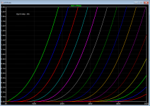
Tung Sol 6c6 and 6j7 are identical in datasheet. Others 6j7 is identical or close to 6sj7, but when compared to 6c6 or Tung Sol 6j7, all that below -1.5v is identical or close, those above -1.5v the curve as it's tilted higher (about 1mA) than Tung Sol and higher than the paint model predicted. Below is Radiotron 6j7 model:
Code:
**** 6J7_RAD ******************************************
* Created on 01/04/2019 13:29 using paint_kip.jar
* [url=http://www.dmitrynizh.com/tubeparams_image.htm]Model Paint Tools: Trace Tube Parameters over Plate Curves, Interactively[/url]
* Plate Curves image file: 6j7_rad.png
* Data source link: <plate curves URL>
*----------------------------------------------------------------------------------
.SUBCKT 6J7_RAD P G2 G K ; LTSpice tetrode.asy pinout
* .SUBCKT 6J7_RAD P G K G2 ; Koren Pentode Pspice pinout
+ PARAMS: MU=20 KG1=3774.9 KP=255.75 KVB=2.136 VCT=5.031E-4 EX=1.367 KG2=3907.93 KNEE=5.569 KVC=1.587
+ KLAMG=8.71E-6   KNK=-0.044 KNG=0.006 KNPL=50 KNSL=11 KNPR=120 KNSR=29
+ CCG=2.6P CGP=1.8P CCP=17P RGI=2000.0
* Vp_MAX=500 Ip_MAX=8 Vg_step=2 Vg_start=0 Vg_count=15
* X_MIN=21 Y_MIN=65 X_SIZE=1045 Y_SIZE=663 FSZ_X=1550 FSZ_Y=878 XYGrid=false
* Rp=1400 Vg_ac=20 P_max=0.75 Vg_qui=-14 Vp_qui=300
* showLoadLine=n showIp=y isDHP=n isPP=n isAsymPP=n isUL=n showDissipLimit=y
* showIg1=n isInputSnapped=y addLocalNFB=n
* XYProjections=n harmonicPlot=y dissipPlot=n
* UL=0.43 EG2=100 gridLevel2=n addKink=y isTanhKnee=n advSigmoid=n
*----------------------------------------------------------------------------------
RE1  7 0  1G    ; DUMMY SO NODE 7 HAS 2 CONNECTIONS
E1   7 0  VALUE=  ; E1 BREAKS UP LONG EQUATION FOR G1.
+{V(G2,K)/KP*LOG(1+EXP((1/MU+(VCT+V(G,K))/SQRT(KVB+V(G2,K)*V(G2,K)))*KP))}
RE2  6 0  1G    ; DUMMY SO NODE 6 HAS 2 CONNECTIONS
E2  6 0  VALUE={(PWR(V(7),EX)+PWRS(V(7),EX))} ; Kg1 times KIT current
RE21 21 0 1
E21  21 0 VALUE={V(6)/KG1*ATAN(V(P,K)/KNEE)} ; Ip with knee but no slope and no kink
RE22 22 0 1 ; E22: kink curr deviation for plate
E22  22 0 VALUE={V(21)*LIMIT(KNK-V(G,K)*KNG,0,0.3)*(-ATAN((V(P,K)-KNPL)/KNSL)+ATAN((V(P,K)-KNPR)/KNSR))}
G1   P  K  VALUE={V(21)*(1+KLAMG*V(P,K)) + V(22)}
* Alexander Gurskii screen current, see audioXpress 2/2011, with slope and kink added
RE43 43 K 1G ; Dummy
E43  43 G2 VALUE={0} ; Dummy
G2   43 K  VALUE={V(6)/KG2*(KVC-ATAN(V(P,K)/KNEE))/(1+KLAMG*V(P,K))-V(22)}
RCP  P K  1G     ; FOR CONVERGENCE
C1   K G  {CCG}  ; CATHODE-GRID 1
C2   G P  {CGP}  ; GRID 1-PLATE
C3   K P  {CCP}  ; CATHODE-PLATE
R1   G 5  {RGI}  ; FOR GRID CURRENT
D3   5 K  DX     ; FOR GRID CURRENT }
.MODEL DX D(IS=1N RS=1 CJO=10PF TT=1N)
.ENDS
*$


* The following triode model is derived from pentode model, see above.
* In the triode model, all spice parameters come directly from the pentode model, except for Kg1,
* which for triode-strapped pentodes is derived from pentode's Kg1, Kg2 and Kvc as
*
*    4Kg1Kg2 / ((2Kvc-Pi)(2Kg1+PiKg2))

**** 6J7_RAD ******************************************
* Created on 01/04/2019 13:29 using paint_kit.jar 4.7
* [url=http://www.dmitrynizh.com/tubeparams_image.htm]Model Paint Tools: Trace Tube Parameters over Plate Curves, Interactively[/url]
* Plate Curves image file: 6j7_rad.png
* Data source link: <plate curves URL>
*----------------------------------------------------------------------------------
.SUBCKT TRIODE_6J7_RAD 1 2 3 ; Plate Grid Cathode
+ PARAMS: CCG=2.6P  CGP=1.8P CCP=17P RGI=2000
+ MU=20 KG1=91856.78 KP=255.75 KVB=2.136 VCT=5.031E-4 EX=1.367
* Vp_MAX=500 Ip_MAX=8 Vg_step=2 Vg_start=0 Vg_count=15
* Rp=1400 Vg_ac=20 P_max=0.75 Vg_qui=-14 Vp_qui=300
* X_MIN=21 Y_MIN=65 X_SIZE=1045 Y_SIZE=663 FSZ_X=1550 FSZ_Y=878 XYGrid=false
* showLoadLine=n showIp=y isDHT=n isPP=n isAsymPP=n showDissipLimit=y
* showIg1=n gridLevel2=n isInputSnapped=y
* XYProjections=n harmonicPlot=y dissipPlot=n
*----------------------------------------------------------------------------------
E1 7 0 VALUE={V(1,3)/KP*LOG(1+EXP(KP*(1/MU+(VCT+V(2,3))/SQRT(KVB+V(1,3)*V(1,3)))))}
RE1 7 0 1G  ; TO AVOID FLOATING NODES
G1 1 3 VALUE={(PWR(V(7),EX)+PWRS(V(7),EX))/KG1}
RCP 1 3 1G   ; TO AVOID FLOATING NODES
C1 2 3 {CCG} ; CATHODE-GRID
C2 2 1 {CGP} ; GRID=PLATE
C3 1 3 {CCP} ; CATHODE-PLATE
D3 5 3 DX ; POSITIVE GRID CURRENT
R1 2 5 {RGI} ; POSITIVE GRID CURRENT
.MODEL DX D(IS=1N RS=1 CJO=10PF TT=1N)
.ENDS
*$
Attachments
Hello.
Does anyone have an EF42 lamp model?
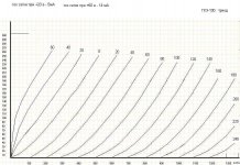
GKE100 in triode
Does anyone have an EF42 lamp model?
GKE100 in triode
Code:
**** GKE100TRIODA ******************************************
* Created on 12/22/2018 09:51 using paint_kit.jar 3.1
* [url=http://www.dmitrynizh.com/tubeparams_image.htm]Model Paint Tools: Trace Tube Parameters over Plate Curves, Interactively[/url]
* Plate Curves image file: gke100trioda.jpg
* Data source link:
*----------------------------------------------------------------------------------
.SUBCKT TRIODE_GKE100TRIODA 1 2 3 ; Plate Grid Cathode
+ PARAMS: CCG=3P  CGP=1.4P CCP=1.9P RGI=2000
+ MU=5.082 KG1=6120 KP=150 KVB=822 VCT=-0.112 EX=1.428
* Vp_MAX=1375 Ip_MAX=300 Vg_step=20 Vg_start=60 Vg_count=16
* Rp=4000 Vg_ac=55 P_max=40 Vg_qui=-48 Vp_qui=300
* X_MIN=39 Y_MIN=127 X_SIZE=825 Y_SIZE=447 FSZ_X=1369 FSZ_Y=640 XYGrid=false
* showLoadLine=n showIp=y isDHT=n isPP=n isAsymPP=n showDissipLimit=y
* showIg1=n gridLevel2=n isInputSnapped=n
* XYProjections=n harmonicPlot=n dissipPlot=n
*----------------------------------------------------------------------------------
E1 7 0 VALUE={V(1,3)/KP*LOG(1+EXP(KP*(1/MU+(VCT+V(2,3))/SQRT(KVB+V(1,3)*V(1,3)))))}
RE1 7 0 1G  ; TO AVOID FLOATING NODES
G1 1 3 VALUE={(PWR(V(7),EX)+PWRS(V(7),EX))/KG1}
RCP 1 3 1G   ; TO AVOID FLOATING NODES
C1 2 3 {CCG} ; CATHODE-GRID
C2 2 1 {CGP} ; GRID=PLATE
C3 1 3 {CCP} ; CATHODE-PLATE
D3 5 3 DX ; POSITIVE GRID CURRENT
R1 2 5 {RGI} ; POSITIVE GRID CURRENT
.MODEL DX D(IS=1N RS=1 CJO=10PF TT=1N)
.ENDS
*$
Attachments
ef42 model:
Code:
**** EF42 ******************************************
* Created on 01/07/2019 09:28 using paint_kip.jar
* [url=http://www.dmitrynizh.com/tubeparams_image.htm]Model Paint Tools: Trace Tube Parameters over Plate Curves, Interactively[/url]
* Plate Curves image file: ef42.png
* Data source link: <plate curves URL>
*----------------------------------------------------------------------------------
.SUBCKT EF42 P G2 G K ; LTSpice tetrode.asy pinout
* .SUBCKT EF42 P G K G2 ; Koren Pentode Pspice pinout
+ PARAMS: MU=83 KG1=383.04 KP=639.35 KVB=3411.97 VCT=0.1775 EX=1.243 KG2=867.3 KNEE=31.09 KVC=1.739
+  KNEE2=20 KNEX=30  KNK=-0.044 KNG=0.006 KNPL=50 KNSL=11 KNPR=120 KNSR=29
+ CCG=9.4P CGP=0.006P CCP=4.3P RGI=2000.0
* Vp_MAX=500 Ip_MAX=35 Vg_step=0.5 Vg_start=0 Vg_count=9
* X_MIN=56 Y_MIN=10 X_SIZE=1006 Y_SIZE=710 FSZ_X=1550 FSZ_Y=878 XYGrid=false
* Rp=1400 Vg_ac=20 P_max=3.5 Vg_qui=-2 Vp_qui=300
* showLoadLine=n showIp=y isDHP=n isPP=n isAsymPP=n isUL=n showDissipLimit=y
* showIg1=n isInputSnapped=y addLocalNFB=n
* XYProjections=n harmonicPlot=y dissipPlot=n
* UL=0.43 EG2=250 gridLevel2=n addKink=y isTanhKnee=y advSigmoid=n
*----------------------------------------------------------------------------------
RE1  7 0  1G    ; DUMMY SO NODE 7 HAS 2 CONNECTIONS
E1   7 0  VALUE=  ; E1 BREAKS UP LONG EQUATION FOR G1.
+{V(G2,K)/KP*LOG(1+EXP((1/MU+(VCT+V(G,K))/SQRT(KVB+V(G2,K)*V(G2,K)))*KP))}
RE2  6 0  1G    ; DUMMY SO NODE 6 HAS 2 CONNECTIONS
E2  6 0  VALUE={(PWR(V(7),EX)+PWRS(V(7),EX))} ; Kg1 times KIT current
RE21 21 0 1
E21  21 0 VALUE={V(6)/KG1*ATAN((V(P,K)+KNEX)/KNEE)*TANH(V(P,K)/KNEE2)} ; Ip with knee but no slope and no kink
RE22 22 0 1 ; E22: kink curr deviation for plate
E22  22 0 VALUE={V(21)*LIMIT(KNK-V(G,K)*KNG,0,0.3)*(-ATAN((V(P,K)-KNPL)/KNSL)+ATAN((V(P,K)-KNPR)/KNSR))}
G1   P  K  VALUE={V(21) + V(22)}
* Alexander Gurskii screen current, see audioXpress 2/2011, with slope and kink added
RE43 43 K 1G ; Dummy
E43  43 G2 VALUE={0} ; Dummy
G2   43 K  VALUE={V(6)/KG2*(KVC-ATAN((V(P,K)+KNEX)/KNEE)*TANH(V(P,K)/KNEE2))-V(22)}
RCP  P K  1G     ; FOR CONVERGENCE
C1   K G  {CCG}  ; CATHODE-GRID 1
C2   G P  {CGP}  ; GRID 1-PLATE
C3   K P  {CCP}  ; CATHODE-PLATE
R1   G 5  {RGI}  ; FOR GRID CURRENT
D3   5 K  DX     ; FOR GRID CURRENT }
.MODEL DX D(IS=1N RS=1 CJO=10PF TT=1N)
.ENDS
*$


* The following triode model is derived from pentode model, see above.
* In the triode model, all spice parameters come directly from the pentode model, except for Kg1,
* which for triode-strapped pentodes is derived from pentode's Kg1, Kg2 and Kvc as
*
*    4Kg1Kg2 / ((2Kvc-Pi)(2Kg1+PiKg2))

**** EF42 ******************************************
* Created on 01/07/2019 09:28 using paint_kit.jar 4.7
* [url=http://www.dmitrynizh.com/tubeparams_image.htm]Model Paint Tools: Trace Tube Parameters over Plate Curves, Interactively[/url]
* Plate Curves image file: ef42.png
* Data source link: <plate curves URL>
*----------------------------------------------------------------------------------
.SUBCKT TRIODE_EF42 1 2 3 ; Plate Grid Cathode
+ PARAMS: CCG=9.4P  CGP=0.006P CCP=4.3P RGI=2000
+ MU=83 KG1=1131.6 KP=639.35 KVB=3411.97 VCT=0.1775 EX=1.243
* Vp_MAX=500 Ip_MAX=35 Vg_step=0.5 Vg_start=0 Vg_count=9
* Rp=1400 Vg_ac=20 P_max=3.5 Vg_qui=-2 Vp_qui=300
* X_MIN=56 Y_MIN=10 X_SIZE=1006 Y_SIZE=710 FSZ_X=1550 FSZ_Y=878 XYGrid=false
* showLoadLine=n showIp=y isDHT=n isPP=n isAsymPP=n showDissipLimit=y
* showIg1=n gridLevel2=n isInputSnapped=y
* XYProjections=n harmonicPlot=y dissipPlot=n
*----------------------------------------------------------------------------------
E1 7 0 VALUE={V(1,3)/KP*LOG(1+EXP(KP*(1/MU+(VCT+V(2,3))/SQRT(KVB+V(1,3)*V(1,3)))))}
RE1 7 0 1G  ; TO AVOID FLOATING NODES
G1 1 3 VALUE={(PWR(V(7),EX)+PWRS(V(7),EX))/KG1}
RCP 1 3 1G   ; TO AVOID FLOATING NODES
C1 2 3 {CCG} ; CATHODE-GRID
C2 2 1 {CGP} ; GRID=PLATE
C3 1 3 {CCP} ; CATHODE-PLATE
D3 5 3 DX ; POSITIVE GRID CURRENT
R1 2 5 {RGI} ; POSITIVE GRID CURRENT
.MODEL DX D(IS=1N RS=1 CJO=10PF TT=1N)
.ENDS
*$
Attachments
OK, I'm looking for a 0C3 regulator tube model, which I would've thought would be out there already. I haven't found any through Google, by searching this thread, or by starting a new thread in the Tubes/Valves forum (it shows you similar threads once click in the post body area). Can anyone point me to one or copy-paste it here?
Thanks!
Thanks!
Here is my attempt to modify 0C3 based on the above link and datasheet, and you can further adjusted for different manufacturers specs such as nbv (normal break down voltage).
0C3 is 108v octal type tube regulator, max current 40mA.
Code:
.model 0C3 D(Is=10u Rs=30 Cjo=10p nbv=108 bv=115 Ibv=40m Vpk=133 mfg=X type=zener )Attachments
Last edited:
Hi Jackinnj
That sounds promissing!
Unfortunatly, their paper was released some weeks too late to be considered in my recently finished 2-year-project, which claimes to merge the very best approaches found in the web for tube spice modeling.
I just requested their paper, but I’m not sure to get it as an ordinary non-scientist...
If yes, you will get a short summary how their approach performes, and the pro/contras compared to my generic triode model.
Kind regards, Adrian
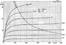
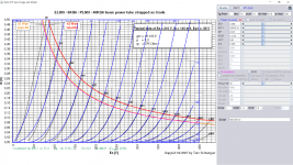
Asking for the model. I attach triode curves.
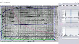
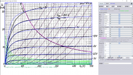
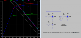
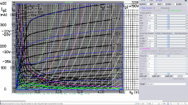
I remodel the triode curve you attached to match the larger scale of corresponding pentode curve so making a larger area to paint. Here is the model:
Code:
**** PL519_P ******************************************
* Created on 01/17/2019 02:14 using paint_kip.jar
* [URL="http://www.dmitrynizh.com/tubeparams_image.htm"]Model Paint Tools: Trace Tube Parameters over Plate Curves, Interactively[/URL]
* Plate Curves image file: pl519_p.png
* Data source link: <plate curves URL>
*----------------------------------------------------------------------------------
.SUBCKT PL519_P P G2 G K ; LTSpice tetrode.asy pinout
* .SUBCKT PL519_P P G K G2 ; Koren Pentode Pspice pinout
+ PARAMS: MU=3.486 KG1=10519.97 KP=28.43 KVB=0 VCT=7.319 EX=2.103 KG2=27051.36 KNEE=15.59 KVC=1.678
+ KLAMG=4.224E-4 KNEE2=20 KNEX=30  KNK=-0.044 KNG=0.006 KNPL=50 KNSL=11 KNPR=120 KNSR=29
+ CCG=0.2P CGP=3P CCP=1P RGI=2000.0
* Vp_MAX=500 Ip_MAX=2000 Vg_step=10 Vg_start=0 Vg_count=22
* X_MIN=134 Y_MIN=47 X_SIZE=868 Y_SIZE=708 FSZ_X=1550 FSZ_Y=878 XYGrid=false
* Rp=1400 Vg_ac=20 P_max=32 Vg_qui=-105 Vp_qui=300
* showLoadLine=n showIp=y isDHP=n isPP=n isAsymPP=n isUL=n showDissipLimit=y
* showIg1=n isInputSnapped=y addLocalNFB=n
* XYProjections=n harmonicPlot=y dissipPlot=n
* UL=0.43 EG2=190 gridLevel2=n addKink=y isTanhKnee=y advSigmoid=n
*----------------------------------------------------------------------------------
RE1  7 0  1G    ; DUMMY SO NODE 7 HAS 2 CONNECTIONS
E1   7 0  VALUE=  ; E1 BREAKS UP LONG EQUATION FOR G1.
+{V(G2,K)/KP*LOG(1+EXP((1/MU+(VCT+V(G,K))/SQRT(KVB+V(G2,K)*V(G2,K)))*KP))}
RE2  6 0  1G    ; DUMMY SO NODE 6 HAS 2 CONNECTIONS
E2  6 0  VALUE={(PWR(V(7),EX)+PWRS(V(7),EX))} ; Kg1 times KIT current
RE21 21 0 1
E21  21 0 VALUE={V(6)/KG1*ATAN((V(P,K)+KNEX)/KNEE)*TANH(V(P,K)/KNEE2)} ; Ip with knee but no slope and no kink
RE22 22 0 1 ; E22: kink curr deviation for plate
E22  22 0 VALUE={V(21)*LIMIT(KNK-V(G,K)*KNG,0,0.3)*(-ATAN((V(P,K)-KNPL)/KNSL)+ATAN((V(P,K)-KNPR)/KNSR))}
G1   P  K  VALUE={V(21)*(1+KLAMG*V(P,K)) + V(22)}
* Alexander Gurskii screen current, see audioXpress 2/2011, with slope and kink added
RE43 43 K 1G ; Dummy
E43  43 G2 VALUE={0} ; Dummy
G2   43 K  VALUE={V(6)/KG2*(KVC-ATAN((V(P,K)+KNEX)/KNEE)*TANH(V(P,K)/KNEE2))/(1+KLAMG*V(P,K))-V(22)}
RCP  P K  1G     ; FOR CONVERGENCE
C1   K G  {CCG}  ; CATHODE-GRID 1
C2   G P  {CGP}  ; GRID 1-PLATE
C3   K P  {CCP}  ; CATHODE-PLATE
R1   G 5  {RGI}  ; FOR GRID CURRENT
D3   5 K  DX     ; FOR GRID CURRENT }
.MODEL DX D(IS=1N RS=1 CJO=10PF TT=1N)
.ENDS
*$


* The following triode model is derived from pentode model, see above.
* In the triode model, all spice parameters come directly from the pentode model, except for Kg1,
* which for triode-strapped pentodes is derived from pentode's Kg1, Kg2 and Kvc as
*
*    4Kg1Kg2 / ((2Kvc-Pi)(2Kg1+PiKg2))

**** PL519_P ******************************************
* Created on 01/17/2019 02:14 using paint_kit.jar 4.7
* [URL="http://www.dmitrynizh.com/tubeparams_image.htm"]Model Paint Tools: Trace Tube Parameters over Plate Curves, Interactively[/URL]
* Plate Curves image file: pl519_p.png
* Data source link: <plate curves URL>
*----------------------------------------------------------------------------------
.SUBCKT TRIODE_PL519_P 1 2 3 ; Plate Grid Cathode
+ PARAMS: CCG=0.2P  CGP=3P CCP=1P RGI=2000
+ MU=3.486 KG1=50076.34 KP=28.43 KVB=0 VCT=7.319 EX=2.103
* Vp_MAX=500 Ip_MAX=2000 Vg_step=10 Vg_start=0 Vg_count=22
* Rp=1400 Vg_ac=20 P_max=32 Vg_qui=-105 Vp_qui=300
* X_MIN=134 Y_MIN=47 X_SIZE=868 Y_SIZE=708 FSZ_X=1550 FSZ_Y=878 XYGrid=false
* showLoadLine=n showIp=y isDHT=n isPP=n isAsymPP=n showDissipLimit=y
* showIg1=n gridLevel2=n isInputSnapped=y
* XYProjections=n harmonicPlot=y dissipPlot=n
*----------------------------------------------------------------------------------
E1 7 0 VALUE={V(1,3)/KP*LOG(1+EXP(KP*(1/MU+(VCT+V(2,3))/SQRT(KVB+V(1,3)*V(1,3)))))}
RE1 7 0 1G  ; TO AVOID FLOATING NODES
G1 1 3 VALUE={(PWR(V(7),EX)+PWRS(V(7),EX))/KG1}
RCP 1 3 1G   ; TO AVOID FLOATING NODES
C1 2 3 {CCG} ; CATHODE-GRID
C2 2 1 {CGP} ; GRID=PLATE
C3 1 3 {CCP} ; CATHODE-PLATE
D3 5 3 DX ; POSITIVE GRID CURRENT
R1 2 5 {RGI} ; POSITIVE GRID CURRENT
.MODEL DX D(IS=1N RS=1 CJO=10PF TT=1N)
.ENDS
*$
Attachments
Last edited:
Could anyone explain the meaning of those parameters in pentode paint program? I'd like to make models for some tubes I have, but I really have not a clue what is related to what. For example, what is related to curve slope, what for curve spacing, minimum/maximum grid curve position, what for saturation mode slope?
@rankot
This page explains how to use the tool: Model Paint Tools: Trace Tube Parameters over Plate Curves, Interactively
This page explains how to use the tool: Model Paint Tools: Trace Tube Parameters over Plate Curves, Interactively
Tried that, but that is explanation for triode only. I need info on pentode params.
Also, does anyone have some advanced vari-mu or remote cutoff pentode model, like Derk (from dos4ever.com) willing to share it? I'm looking for models for EF183, PCF201 and PCF801, but without the success.
Also, does anyone have some advanced vari-mu or remote cutoff pentode model, like Derk (from dos4ever.com) willing to share it? I'm looking for models for EF183, PCF201 and PCF801, but without the success.
- Home
- Amplifiers
- Tubes / Valves
- Vacuum Tube SPICE Models