jazbo8, that's one of Duncan Munro's models.Making slight headway, the Koren model I used came from Intact Audio, that's why the curves were different from yours:
Code:.SUBCKT 6SN7GTB A G K XV1 A G K TRIODENH +PARAMS: LIP= 1 LIF= 0.0037 RAF= 0.02 RAS= 2 CDO= 0 + RAP= 0.002 ERP= 1.4 + MU0= 19.2642 MUR= 0.006167 EMC= 0.0000189 + GCO= 0 GCF= 0.000213 + CGA=3.90E-12 CGK=2.40E-12 CAK=7.00E-13 .ENDS

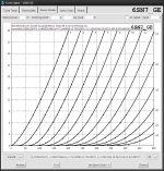
popilin, here's a 6SN7 model I made using Curve Captor:
Code:
* 6SN7_GE LTSpice model
* Modified Koren model (8 parameters): mean fit error 0.0771164mA
* Traced by Wayne Clay on 10/11/2013 using Curve Captor v0.9.1
* from General Elctric data sheet
.subckt 6SN7_GE  P G K
    Bp  P K  I=
+ (0.01996138472m)*uramp(V(P,K)*ln(1.0+(-0.06003194624)+exp((4.721146098)+
+ (4.721146098)*((20.78010878)+(-111.9910206m)*V(G,K))*V(G,K)/sqrt((29.06231184)**2+
+ (V(P,K)-(6.821890538))**2)))/(4.721146098))**(1.378722311)
  Cgk G K 2.8p ; 0.2p added
  Cpk P K 2.2p ; 0.5p added
  Cgp G P 4.5p ; 0.5p added
  Rpk P K 1G ; to avoid floating nodes
  d3  G K dx1
.model dx1 d(is=1n rs=2k cjo=1pf N=1.5 tt=1n)
.endsAttachments
Hi cogsncogs
Good to see you around here !
Your model looks very very good, and yields about -50 dB 2nd with Morgan Jones circuit, very very close.
As usual, your models beat any other.
Good to see you around here !
Your model looks very very good, and yields about -50 dB 2nd with Morgan Jones circuit, very very close.
As usual, your models beat any other.
Attachments
Last edited:
LTSpice Tutorial
Here is a very useful link for LTSpice newbies and for those who might need a refresher.. This excellent tutorial is located on the simonbramble.co.uk website here:
LTspice Tutorial | The Complete Course
Here is a very useful link for LTSpice newbies and for those who might need a refresher.. This excellent tutorial is located on the simonbramble.co.uk website here:
LTspice Tutorial | The Complete Course
I copied over my post in an LTSpice thread in software tools because I thought it might be useful, it details how to install tube libraries in LTSpice.. Unfortunately I can't change the date of the original post made on 12/19/13..
http://www.diyaudio.com/forums/tubes-valves/243950-vacuum-tube-spice-models-12.html#post3751418
http://www.diyaudio.com/forums/tubes-valves/243950-vacuum-tube-spice-models-12.html#post3751418
Curve Captor is just another way to capture tube curves, latest version is here:
Curve Captor | Free Science & Engineering software downloads at SourceForge.net
I've not used it in the last few years.. (It is very good for tracing triodes and runs under tcl in windows or linux - last time I used it.) I will probably be using it again in the future.
More details here:http://www.diyaudio.com/forums/tube...be-modeling-software-beta-testers-wanted.html
I had a brief flirtation with this and paint_kit for triodes, and paint_kip a few years ago, and then did not need the functionality, had some computer meltdowns.. Having bought and built a uTracer early this year I now have the motivation to use tracers again as I have not had much luck with pentode models generated by the uTracer alternate gui - I'm probably doing something wrong..
Hm-m-m-m, unfortunately I do not run Unix (PC w/MS Vista), nor have access to those ancillary programs mentioned.
While I have been wanting to get into using something like LTSPICE, I would just as easily prefer dumping everything (equations, constants, variables) into a spreadsheet and use the plot function to create the resultant curve graphs.
General Q: Is Curve Captor better/worse/same than Model Paint Tools?
I get good results with the latest versions of paint_kit, and paint_kip. I've not reevaluated Curve Captor recently so can't say, the last version I used worked quite well..
Paint runs in java from the command line in windows and has a nice gui.
Curve Captor runs in TCL which is available free from a variety of sources on the web and runs just fine in Windows last time I used it.
All of this software is free for personal use, some is open source and free for any use.
Paint runs in java from the command line in windows and has a nice gui.
Curve Captor runs in TCL which is available free from a variety of sources on the web and runs just fine in Windows last time I used it.
All of this software is free for personal use, some is open source and free for any use.
For diodes and triodes, I prefer Curve Captor.Hm-m-m-m, unfortunately I do not run Unix (PC w/MS Vista), nor have access to those ancillary programs mentioned.
While I have been wanting to get into using something like LTSPICE, I would just as easily prefer dumping everything (equations, constants, variables) into a spreadsheet and use the plot function to create the resultant curve graphs.
General Q: Is Curve Captor better/worse/same than Model Paint Tools?
You can trace directly from data sheet Plate Characteristics curves, Grid-Plate Transfer curves or enter data directly from csv, spreadsheet files etc.
Simulate load lines with calculated THD from 'captured' curves.
Model types:
Child-Langmuir law
Child-Langmuir law with contact potential
Rydel model 4 parameters
Rydel model 5 parameters
Koren model 4 parameters
Koren model 5 parameters
Modified Koren model 6 parameters
Modified Koren model 8 parameters
Outputs to: 3f4 Spice, PSpice, LTSpice and CircuitMaker.
I've ran Curve Captor on Windoze® XP, Vista and 7 without any problems. Be sure to install a Tcl package first. I recommend ActiveTcl. Install/unzip both on your system drive C:\
Ip-Eg curves can be derived from Ip-Ep curves, and follow the "same" 3/2 power law, so curvature meaning is the same.
That's true for the Ayumi model but perhaps not the Koren model which uses the generic diode SPICE model.
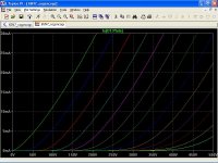
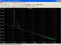
I don't find any difference with this FFT analysis -- the amplifier is basically SY's "Impasse" using the optimized Koren model, and the Ayumi model:
Does the Impasse use LEDs for biasing the bottom triode?
jazbo8, that's one of Duncan Munro's models.
I just assumed that everyone use the drop-down tube manual in LTSpice from Intact... Thanks for the clarification.
Does the Impasse use LEDs for biasing the bottom triode?
Never mind, found it - LEDs in the cathode.
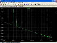
I don't find any difference with this FFT analysis -- the amplifier is basically SY's "Impasse" using the optimized Koren model, and the Ayumi model:
An externally hosted image should be here but it was not working when we last tested it.
You're kidding, right?
Here are the parameters from the optimized koren model -- of course there are a lot of moving parts so there are a lot of optimal solutions:
Params: MU=21.54 KP=133.1 KVB=350.9 EX=1.378 KG1=1445
I use graph-grabber for capturing data
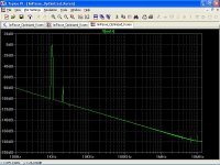
SY's ImPasse
6SN7 Koren model
2nd -65 dB THD 0.054%
6SN7 Optimized Koren model
2nd -60 dB THD 0.095%
6SN7 Ayumi Nakabayashi model
2nd -51 dB THD 0.26%
Again, with Norman Koren model, THD is close to 0.04% at 20Vp claimed by SY.
Attachments
Last edited:
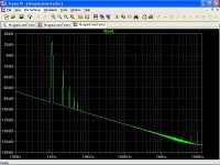
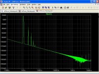
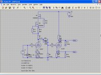
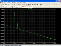
Here's what the Impasse looks like in reality:
Just look at the first stage, remove the depletion MOSFETs and assume an 8mA source @350V, and a resistive load of 1.5 meg
An externally hosted image should be here but it was not working when we last tested it.
Just look at the first stage, remove the depletion MOSFETs and assume an 8mA source @350V, and a resistive load of 1.5 meg
SY's ImPasse 2V RMS
6SN7 Koren model
2nd -82 dB THD 0.008%
6SN7 Optimized Koren model
2nd -77 dB THD 0.014%
6SN7 Ayumi Nakabayashi model
2nd -68 dB THD 0.037%
Again, with Norman Koren model, THD is close to 0.01% claimed by SY.
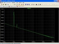
6SN7 Koren model
2nd -82 dB THD 0.008%
6SN7 Optimized Koren model
2nd -77 dB THD 0.014%
6SN7 Ayumi Nakabayashi model
2nd -68 dB THD 0.037%
Again, with Norman Koren model, THD is close to 0.01% claimed by SY.
Attachments
Last edited:
12BY7A Model
Someone on another forum pointed out that the 12BY7A model in Ayumi's pctube package is far from accurate, so I tried to make a new one, but the result is still so-so... If you have a better one, please post it.
Someone on another forum pointed out that the 12BY7A model in Ayumi's pctube package is far from accurate, so I tried to make a new one, but the result is still so-so... If you have a better one, please post it.
Code:
*
* Generic pentode model: 12BY7A_AN
* Copyright 2003--2008 by Ayumi Nakabayashi, All rights reserved.
* Version 3.10, Generated on Fri Dec 27 09:04:07 2013
*                 Plate
*                 | Screen Grid
*                 | |  Control Grid
*                 | |  |  Cathode
*                 | |  |  |
.SUBCKT 12BY7A_AN A G2 G1 K
BGG   GG   0 V=V(G1,K)+0.65943158
BM1   M1   0 V=(0.012147484*(URAMP(V(G2,K))+1e-10))**-0.63410138
BM2   M2   0 V=(0.70287195*(URAMP(V(GG)+URAMP(V(G2,K))/24.460049)))**2.1341014
BP    P    0 V=0.0067627064*(URAMP(V(GG)+URAMP(V(G2,K))/34.80015))**1.5
BIK   IK   0 V=U(V(GG))*V(P)+(1-U(V(GG)))*0.0039175034*V(M1)*V(M2)
BIG   IG   0 V=0.0033813532*URAMP(V(G1,K))**1.5*(URAMP(V(G1,K))/(URAMP(V(A,K))+URAMP(V(G1,K)))*1.2+0.4)
BIK2  IK2  0 V=V(IK,IG)*(1-0.4*(EXP(-URAMP(V(A,K))/URAMP(V(G2,K))*15)-EXP(-15)))
BIG2T IG2T 0 V=V(IK2)*(0.82100762*(1-URAMP(V(A,K))/(URAMP(V(A,K))+10))**1.5+0.17899238)
BIK3  IK3  0 V=V(IK2)*(URAMP(V(A,K))+5958)/(URAMP(V(G2,K))+5958)
BIK4  IK4  0 V=V(IK3)-URAMP(V(IK3)-(0.0036749321*(URAMP(V(A,K))+URAMP(URAMP(V(G2,K))-URAMP(V(A,K))))**1.5))
BIP   IP   0 V=URAMP(V(IK4,IG2T)-URAMP(V(IK4,IG2T)-(0.0036749321*URAMP(V(A,K))**1.5)))
BIAK  A    K I=V(IP)+1e-10*V(A,K)
BIG2  G2   K I=URAMP(V(IK4,IP))
BIGK  G1   K I=V(IG)
* CAPS
CGA   G1  A  0.063p
CGK   G1  K  6p
C12   G1  G2 4p
CAK   A   K  3.5p
.ENDSI have a certain amount of new/unused C3G. These are top class small signal tubes.
For most of them Ayumis model is perfect (both, pentode and triode model).
However, one third of my C3G`s has a totally different operating point which has no logic with data-sheet.
A similar story is with E80L, E180F ...
I am inclined to the opinion that the difference in the models is less than in the tubes of the same manufacturer.
- Home
- Amplifiers
- Tubes / Valves
- Vacuum Tube SPICE Models