1AD4 Pentode SPICE Model
Code:
*
* Generic pentode model: 1AD4_AN
* Copyright 2003--2008 by Ayumi Nakabayashi, All rights reserved.
* Version 3.10, Generated on Fri May 26 09:48:27 2017
*               Anode
*               | Screen Grid
*               | |  Control Grid
*               | |  |  Cathode
*               | |  |  |
.SUBCKT 1AD4_AN A G2 G1 K
BGG   GG   0 V=V(G1,K)+-0.2
BM1   M1   0 V=(0.033333333*(URAMP(V(G2,K))+1e-10))**-1
BM2   M2   0 V=(0.6*(URAMP(V(GG)+URAMP(V(G2,K))/12)))**2.5
BP    P    0 V=0.0015*(URAMP(V(GG)+URAMP(V(G2,K))/20))**1.5
BIK   IK   0 V=U(V(GG))*V(P)+(1-U(V(GG)))*0.001*V(M1)*V(M2)
BIG   IG   0 V=0.00075*URAMP(V(G1,K))**1.5*(URAMP(V(G1,K))/(URAMP(V(A,K))+URAMP(V(G1,K)))*1.2+0.4)
BIK2  IK2  0 V=V(IK,IG)*(1-0.4*(EXP(-URAMP(V(A,K))/URAMP(V(G2,K))*15)-EXP(-15)))
BIG2T IG2T 0 V=V(IK2)*(0.9*(1-URAMP(V(A,K))/(URAMP(V(A,K))+10))**1.5+0.1)
BIK3  IK3  0 V=V(IK2)*(URAMP(V(A,K))+2430)/(URAMP(V(G2,K))+2430)
BIK4  IK4  0 V=V(IK3)-URAMP(V(IK3)-(0.00086389475*(URAMP(V(A,K))+URAMP(URAMP(V(G2,K))-URAMP(V(A,K))))**1.5))
BIP   IP   0 V=URAMP(V(IK4,IG2T)-URAMP(V(IK4,IG2T)-(0.00086389475*URAMP(V(A,K))**1.5)))
BIAK  A    K I=V(IP)+1e-10*V(A,K)
BIG2  G2   K I=URAMP(V(IK4,IP))
BIGK  G1   K I=V(IG)
* CAPS
CGA   G1  A  0.01p
CGK   G1  K  2.4p
C12   G1  G2 1.6p
CAK   A   K  4p
.ENDSHello jazbo8,Do you have the pentode characteristic for the 1P24B? The one I have does not seem to correlate with the triode characteristic that you provided.
View attachment 618205
Also, I tried making the pentode model for 1T4, but the result was way off from the characteristic shown in the GE datasheet, so it's not really usable.
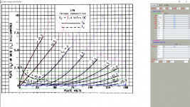
I have attached the the pentode characteristic for the 1P24B as blow:

I got the information from http://www.radiovilag.hu/images/1P24B.pdf, hope it will be useful.
Koonw helped me created 1T4 model (see page 135, post #1346) before, but the model was not running well with ltpice, especially the triode model. Thanks for trying! I checked the triode curve of 1T4 on Tung-sol data sheet, it is the same as on GE datasheet.
Thanks for creating the 1AD4 model
")
Thank you again for your helping!
Below is the triode characteristic of the 1P24B that you posted earlier, as you can see, the plate current is no where near where it should be, if you compare it to the pentode characteristic (~17mA). So you need to trace the triode characteristic yourself, as the one in the datasheet is most likely incorrect.

I suspect the triode or the pentode characteristic shown in the datasheets isn't right (just not sure which), if you have the tube, it might be helpful if you can trace them to see what's going on.I checked the triode curve of 1T4 on Tung-sol data sheet, it is the same as on GE datasheet.
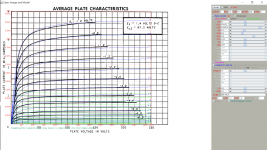
Found 1T4 triode curve in Tung-sol datasheet, Mu used in the previous paint plot is too high so why that triode plot is not correct. Here is direct plot from the datasheet:
Code:
**** IT4_TS ******************************************
* Created on 05/28/2017 02:14 using paint_kit.jar 3.0
* [URL="http://www.dmitrynizh.com/tubeparams_image.htm"]Model Paint Tools: Trace Tube Parameters over Plate Curves, Interactively[/URL]
* Plate Curves image file: it4-ts.png
* Data source link:
*----------------------------------------------------------------------------------
.SUBCKT IT4_TS_T 1 2 3 ; Plate Grid Cathode
+ PARAMS: CCG=3.6P  CGP=0.01P CCP=7.5P RGI=2380
+ MU=9.8 KG1=1.271E8 KP=62 KVB=18.4 VCT=8.64 EX=4.6
* Vp_MAX=150 Ip_MAX=10 Vg_step=2.5 Vg_start=5 Vg_count=13
* Rp=4000 Vg_ac=55 P_max=0.5 Vg_qui=-48 Vp_qui=300
* X_MIN=193 Y_MIN=121 X_SIZE=1080 Y_SIZE=709 FSZ_X=1860 FSZ_Y=948 XYGrid=true
* showLoadLine=n showIp=y isDHT=n isPP=n isAsymPP=n showDissipLimit=y
* showIg1=y gridLevel2=n isInputSnapped=n
* XYProjections=n harmonicPlot=n harmonics=y
*----------------------------------------------------------------------------------
E1 7 0 VALUE={V(1,3)/KP*LOG(1+EXP(KP*(1/MU+(VCT+V(2,3))/SQRT(KVB+V(1,3)*V(1,3)))))}
RE1 7 0 1G  ; TO AVOID FLOATING NODES
G1 1 3 VALUE={(PWR(V(7),EX)+PWRS(V(7),EX))/KG1}
RCP 1 3 1G   ; TO AVOID FLOATING NODES
C1 2 3 {CCG} ; CATHODE-GRID
C2 2 1 {CGP} ; GRID=PLATE
C3 1 3 {CCP} ; CATHODE-PLATE
D3 5 3 DX ; POSITIVE GRID CURRENT
R1 2 5 {RGI} ; POSITIVE GRID CURRENT
.MODEL DX D(IS=1N RS=1 CJO=10PF TT=1N)
.ENDS
*$
Attachments
1T4 Pentode SPICE Model
Ayumi's model has a better match to the pentode characteristic from Tung-Sol (compared to GE's), it's still off a little for Eg1 <= -4V, anyway, it should be usable.
Ayumi's model has a better match to the pentode characteristic from Tung-Sol (compared to GE's), it's still off a little for Eg1 <= -4V, anyway, it should be usable.
Code:
*
* Generic pentode model: 1T4_AN
* Copyright 2003--2008 by Ayumi Nakabayashi, All rights reserved.
* Version 3.10, Generated on Sun May 28 08:16:49 2017
*              Anode
*              | Screen Grid
*              | |  Control Grid
*              | |  |  Cathode
*              | |  |  |
.SUBCKT 1T4_AN A G2 G1 K
BGG   GG   0 V=V(G1,K)+-0.73060462
BM1   M1   0 V=(0.15308956*(URAMP(V(G2,K))+1e-10))**-3.5390245
BM2   M2   0 V=(0.29767667*(URAMP(V(GG)+URAMP(V(G2,K))/4.5876632)))**5.0390245
BP    P    0 V=0.00075222059*(URAMP(V(GG)+URAMP(V(G2,K))/15.411565))**1.5
BIK   IK   0 V=U(V(GG))*V(P)+(1-U(V(GG)))*0.015691567*V(M1)*V(M2)
BIG   IG   0 V=0.0003761103*URAMP(V(G1,K))**1.5*(URAMP(V(G1,K))/(URAMP(V(A,K))+URAMP(V(G1,K)))*1.2+0.4)
BIK2  IK2  0 V=V(IK,IG)*(1-0.4*(EXP(-URAMP(V(A,K))/URAMP(V(G2,K))*15)-EXP(-15)))
BIG2T IG2T 0 V=V(IK2)*(0.72760171*(1-URAMP(V(A,K))/(URAMP(V(A,K))+10))**1.5+0.27239829)
BIK3  IK3  0 V=V(IK2)*(URAMP(V(A,K))+3757.5)/(URAMP(V(G2,K))+3757.5)
BIK4  IK4  0 V=V(IK3)-URAMP(V(IK3)-(0.00045049865*(URAMP(V(A,K))+URAMP(URAMP(V(G2,K))-URAMP(V(A,K))))**1.5))
BIP   IP   0 V=URAMP(V(IK4,IG2T)-URAMP(V(IK4,IG2T)-(0.00045049865*URAMP(V(A,K))**1.5)))
BIAK  A    K I=V(IP)+1e-10*V(A,K)
BIG2  G2   K I=URAMP(V(IK4,IP))
BIGK  G1   K I=V(IG)
* CAPS
CGA   G1  A  0.01p
CGK   G1  K  2.2p
C12   G1  G2 1.4p
CAK   A   K  7.5p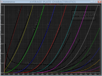
.ENDSHi there, I am redoing 1t4 paint plot using Mu value about 10. Here is the pentode paint plot and Ia + Ig2 in triode strapped mode. For such a small tube, Ig2 has greater influence on the overall plot and over the range as it contributed quite larger a portion to the output esp at A2 (where grid positive) portion. Toward the far end everybody was out by a few margin, esp the original datasheet :-(
I also plotted the triode strapped of the paint model, but the triode model has not been checked.
I put my best foot forward and here is the result:
I also plotted the triode strapped of the paint model, but the triode model has not been checked.
I put my best foot forward and here is the result:
Code:
**** 1T4_GE ******************************************
* Created on 05/28/2017 20:10 using paint_kip.jar
* [url=http://www.dmitrynizh.com/tubeparams_image.htm]Model Paint Tools: Trace Tube Parameters over Plate Curves, Interactively[/url]
* Plate Curves image file: 1t4_ge.png
* Data source link: <plate curves URL>
*----------------------------------------------------------------------------------
.SUBCKT PENT_1T4_GE 1 2 3 4 ; P G K G2
+ PARAMS: CCG=3P  CGP=1.4P CCP=1.9P RGI=2000
+ MU=9.8 KG1=57063.2 KP=37.3 KVB=8.22 KVC=5.28 VCT=0.465 EX=2.11 KG2=476262.4
* Vp_MAX=250 Ip_MAX=4 Vg_step=0.5 Vg_start=0 Vg_count=17
* Rp=1600 Vg_ac=23.5 P_max=7.5 Vg_qui=-23.4 Vp_qui=240 UL=0.43 EG2=67.5
* X_MIN=79 Y_MIN=45 X_SIZE=1006 Y_SIZE=812 FSZ_X=1942 FSZ_Y=1102 XYGrid=true
* showLoadLine=n showIp=y isDHP=n isPP=n isAsymPP=n isUL=n showDissipLimit=y
* showIg1=y gridLevel2=n isInputSnapped=n
* XYProjections=n harmonicPlot=y harmonics=y
*----------------------------------------------------------------------------------
RE1  7 0  1G    ; DUMMY SO NODE 7 HAS 2 CONNECTIONS
E1   7 0  VALUE=  ; E1 BREAKS UP LONG EQUATION FOR G1.
+{V(4,3)/KP*LOG(1+EXP((1/MU+(VCT+V(2,3))/V(4,3))*KP))}
G1   1 3  VALUE={(PWR(V(7),EX)+PWRS(V(7),EX))/KG1*ATAN(V(1,3)/KVB)}
* Alexander Gurskii screen current, see audioXpress 2/2011
RE2  8 3 1G ; Dummy
G2   8 3  VALUE={(PWR(V(7),EX)+PWRS(V(7),EX))/KG2*(KVC-ATAN(V(1,3)/KVB))}
E2   8 4 VALUE={0} ; Dummy
RCP  1 3  1G      ; FOR CONVERGENCE
C1   2 3  {CCG}    ; CATHODE-GRID 1
C2   1 2  {CGP}  ; GRID 1-PLATE
C3   1 3  {CCP}   ; CATHODE-PLATE
R1   2 5  {RGI}   ; FOR GRID CURRENT
D3   5 3  DX      ; FOR GRID CURRENT
.MODEL DX D(IS=1N RS=1 CJO=10PF TT=1N)
.ENDS
*$
Code:
 * The following triode model is derived from pentode model, see above.
* In the triode model, all spice parameters come directly from the pentode model, except for Kg1,
* which for triode-strapped pentodes is derived from pentode's Kg1, Kg2 and Kvc as
*
*    4Kg1Kg2 / (2Kvc-Pi)(2Kg1+PiKg2)

**** 1T4_GE ******************************************
* Created on 05/28/2017 20:10 using paint_kit.jar 3.3
* [url=http://www.dmitrynizh.com/tubeparams_image.htm]Model Paint Tools: Trace Tube Parameters over Plate Curves, Interactively[/url]
* Plate Curves image file: 1t4_ge.png
* Data source link: <plate curves URL>
*----------------------------------------------------------------------------------
.SUBCKT TRIODE_1T4_GE 1 2 3 ; Plate Grid Cathode
+ PARAMS: CCG=3P  CGP=1.4P CCP=1.9P RGI=2000
+ MU=9.8 KG1=9111.6 KP=37.3 KVB=8.22 VCT=0.465 EX=2.11
* Vp_MAX=250 Ip_MAX=4 Vg_step=0.5 Vg_start=0 Vg_count=17
* Rp=1600 Vg_ac=23.5 P_max=7.5 Vg_qui=-23.4 Vp_qui=240
* X_MIN=79 Y_MIN=45 X_SIZE=1006 Y_SIZE=812 FSZ_X=1942 FSZ_Y=1102 XYGrid=true
* showLoadLine=n showIp=y isDHT=n isPP=n isAsymPP=n showDissipLimit=y
* showIg1=y gridLevel2=n isInputSnapped=n
* XYProjections=n harmonicPlot=y harmonics=y
*----------------------------------------------------------------------------------
E1 7 0 VALUE={V(1,3)/KP*LOG(1+EXP(KP*(1/MU+(VCT+V(2,3))/SQRT(KVB+V(1,3)*V(1,3)))))}
RE1 7 0 1G  ; TO AVOID FLOATING NODES
G1 1 3 VALUE={(PWR(V(7),EX)+PWRS(V(7),EX))/KG1}
RCP 1 3 1G   ; TO AVOID FLOATING NODES
C1 2 3 {CCG} ; CATHODE-GRID
C2 2 1 {CGP} ; GRID=PLATE
C3 1 3 {CCP} ; CATHODE-PLATE
D3 5 3 DX ; POSITIVE GRID CURRENT
R1 2 5 {RGI} ; POSITIVE GRID CURRENT
.MODEL DX D(IS=1N RS=1 CJO=10PF TT=1N)
.ENDS
*$
Attachments
Does anyone have a good spice model for the DN2540 and 10M40, known to work in LTSpice that they can post here? While obviously not a tube, they are often employed in conjunction with tubes.
I use this one in my standard.mos file. I think it's from supertex.lib:
Code:
.MODEL DN2540 NMOS (LEVEL=3 RS=1.05 NSUB=5.0E14 DELTA=0.1 KAPPA=0.20 TPG=1 CGDO=3.1716E-10 RD=11 VTO=-1.50 VMAX=1.0E7 ETA=0.0223089 NFS=6.6E10 TOX=725E-10 LD=1.698E-9 UO=862.425 XJ=6.4666E-7 THETA=1.0E-5 CGSO=2.50E-9 L=4.0E-6 W=59E-3)It's not been super accurate, but it seems fairly close.
Here's one I picked up somewhere for 10M45S. I haven't compared it to reality, so YMMV.
Code:
******************************************************
* Model generated on 27 Apr 2010
* Model format: LTspice
* IXCP10M45 macro model
* External node designations
* Node A -> anode (1)
* Node G -> gate (2)
* Node K -> cathode (3)
*
* G1, R1 & C1 model an idealized op-amp. Aol controls
* its open loop gain. Based on LT opamp.lib.
* The op-amp controls a MOSFET M1, to make the Voltage
* drop across a resistor between G & K equal a Voltage
* reference. The Vref source is made up by G2 & R2.
* It is altered by a fraction of V(A,K) to achieve a
* dynamic resistance of 160k where bias resistor = 300R,
* giving nominally 10mA of Ik.
******************************************************

.subckt 10M45S A G K
+params: Aol=100 GBW=10meg ref=3

M1 A 5 K K MOSFET1
* V1 4 G 3
G1 G 5 4 K {Aol}
R1 5 G 1
C1 5 G {Aol/GBW/6.28318530717959}
G2 G 4 value={(ref+V(A,K)/500)}
R2 4 G 1

.model MOSFET1 VDMOS(Rg=2 Vto=4.85 Rd=1m Rs=1m Rb=1.2m Kp=33
+lambda=0.01 Cgs=1.4n Cgdmin=48p Cgdmax=1.9n Cjo=4n Is=2n Vds=450
+Ron=0.92 Qg=48n)
.ends
While I'm at it, here's one for LND150, also from supertex.lib:
Code:
.MODEL LND150 VDMOS (Rd=450 VTO=-1.35 Kp=2m Cgdmax=1p Cgdmin=0.25p Cgs=7.5p)--
Last edited:
6HB6, anyone?
It's not in Ayumi's pctube collection. I googled for it, nothing came up. So... Anybody here ever played with this one?
http://www.nj7p.org/Tubes/PDFs/Frank/135-GE/6HB6.pdf
And... Triode curves! I hope these are good enough.
10 mA/div vert., 50V/div horiz., g2 100V, 1.4V steps on g1, g3 0V
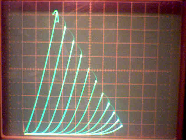
http://www.diyaudio.com/forums/atta...-suppresor-grid-used-feedback-6hb6_triode.jpg
--
It's not in Ayumi's pctube collection. I googled for it, nothing came up. So... Anybody here ever played with this one?
http://www.nj7p.org/Tubes/PDFs/Frank/135-GE/6HB6.pdf
And... Triode curves! I hope these are good enough.
10 mA/div vert., 50V/div horiz., g2 100V, 1.4V steps on g1, g3 0V
http://www.diyaudio.com/forums/atta...-suppresor-grid-used-feedback-6hb6_triode.jpg
--
Last edited:
6HB6 Pentode SPICE Model
Code:
*
* Generic pentode model: 6HB6_AN
* Copyright 2003--2008 by Ayumi Nakabayashi, All rights reserved.
* Version 3.10, Generated on Mon Jul 06 11:26:14 2015
*               Plate
*               | Screen Grid
*               | |  Control Grid
*               | |  |  Cathode
*               | |  |  |
.SUBCKT 6HB6_AN A G2 G1 K
BGG   GG   0 V=V(G1,K)+0.46957501
BM1   M1   0 V=(0.018964993*(URAMP(V(G2,K))+1e-10))**-0.96067364
BM2   M2   0 V=(0.60958917*(URAMP(V(GG)+URAMP(V(G2,K))/20.585867)))**2.4606736
BP    P    0 V=0.012979226*(URAMP(V(GG)+URAMP(V(G2,K))/33.770067))**1.5
BIK   IK   0 V=U(V(GG))*V(P)+(1-U(V(GG)))*0.00845948*V(M1)*V(M2)
BIG   IG   0 V=0.006489613*URAMP(V(G1,K))**1.5*(URAMP(V(G1,K))/(URAMP(V(A,K))+URAMP(V(G1,K)))*1.2+0.4)
BIK2  IK2  0 V=V(IK,IG)*(1-0.4*(EXP(-URAMP(V(A,K))/URAMP(V(G2,K))*15)-EXP(-15)))
BIG2T IG2T 0 V=V(IK2)*(0.87238117*(1-URAMP(V(A,K))/(URAMP(V(A,K))+10))**1.5+0.12761883)
BIK3  IK3  0 V=V(IK2)*(URAMP(V(A,K))+950)/(URAMP(V(G2,K))+950)
BIK4  IK4  0 V=V(IK3)-URAMP(V(IK3)-(0.0070703719*(URAMP(V(A,K))+URAMP(URAMP(V(G2,K))-URAMP(V(A,K))))**1.5))
BIP   IP   0 V=URAMP(V(IK4,IG2T)-URAMP(V(IK4,IG2T)-(0.0070703719*URAMP(V(A,K))**1.5)))
BIAK  A    K I=V(IP)+1e-10*V(A,K)
BIG2  G2   K I=URAMP(V(IK4,IP))
BIGK  G1   K I=V(IG)
* CAPS
CGA   G1  A  0.18p
CGK   G1  K  7.8p
C12   G1  G2 5.2p
CAK   A   K  8p
.ENDSI use this one in my standard.mos file. I think it's from supertex.lib:
<snip>
This has been the subterfuge I used successfully in LTSpiceIV, I unfortunately have to report that this doesn't work in the 64 bit version of LTSpice XVII that I am now using. You can still edit the standard.mos file, but even after restarting LTSpice it ignores the entries. The values listed (variable names) are not correct for the new version either, I think they've changed the model used.
Adding Tube Models to LTspiceXVII
Here's how I got this working with the least amount of futzing around:
edit the tube's .inc file (assuming Aymui's zip here) replacing ^ with **
File->Open in LTspiceXVII
select "show all files *.*"
Open FILENAME.inc
The netlist should open.
Right click on the .SUBCKT line and select "Create New Symbol"
A dialog should pop up asking if you want to do this automatically.
You will now have the .asy file inside My Documents\LTspiceXVII\lib\sym\AutoGenerated
You can now also "Save as" and place it in your global sym folder if you wish.
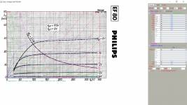
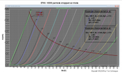
Here is the closest model for ef80 I painted. A known pentrode strapped triode curve helps a lot.
Code:
**** EF80 ******************************************
* Created on 06/30/2017 03:10 using paint_kip.jar
* [URL="http://www.dmitrynizh.com/tubeparams_image.htm"]Model Paint Tools: Trace Tube Parameters over Plate Curves, Interactively[/URL]
* Plate Curves image file: ef80.png
* Data source link: <plate curves URL>
*----------------------------------------------------------------------------------
.SUBCKT EF80 1 2 3 4 ; P G K G2
+ PARAMS: CCG=7.5P  CGP=3.3P CCP=0.012P RGI=2000
+ MU=50 KG1=461.8 KP=261.8 KVB=22.2 KVC=1.57 VCT=0 EX=1.25 KG2=169.3
* Vp_MAX=350 Ip_MAX=50 Vg_step=1 Vg_start=0 Vg_count=8
* Rp=1600 Vg_ac=23.5 P_max=2.5 Vg_qui=-23.4 Vp_qui=240 UL=0.43 EG2=170
* X_MIN=69 Y_MIN=84 X_SIZE=953 Y_SIZE=683 FSZ_X=1942 FSZ_Y=1102 XYGrid=false
* showLoadLine=n showIp=y isDHP=n isPP=n isAsymPP=n isUL=n showDissipLimit=y
* showIg1=n gridLevel2=n isInputSnapped=n
* XYProjections=n harmonicPlot=y harmonics=y
*----------------------------------------------------------------------------------
RE1  7 0  1G    ; DUMMY SO NODE 7 HAS 2 CONNECTIONS
E1   7 0  VALUE=  ; E1 BREAKS UP LONG EQUATION FOR G1.
+{V(4,3)/KP*LOG(1+EXP((1/MU+(VCT+V(2,3))/V(4,3))*KP))}
G1   1 3  VALUE={(PWR(V(7),EX)+PWRS(V(7),EX))/KG1*ATAN(V(1,3)/KVB)}
* Alexander Gurskii screen current, see audioXpress 2/2011
RE2  8 3 1G ; Dummy
G2   8 3  VALUE={(PWR(V(7),EX)+PWRS(V(7),EX))/KG2*(KVC-ATAN(V(1,3)/KVB))}
E2   8 4 VALUE={0} ; Dummy
RCP  1 3  1G      ; FOR CONVERGENCE
C1   2 3  {CCG}    ; CATHODE-GRID 1
C2   1 2  {CGP}  ; GRID 1-PLATE
C3   1 3  {CCP}   ; CATHODE-PLATE
R1   2 5  {RGI}   ; FOR GRID CURRENT
D3   5 3  DX      ; FOR GRID CURRENT
.MODEL DX D(IS=1N RS=1 CJO=10PF TT=1N)
.ENDS
*$
Attachments
The DN2540 model can be found here:
If using the DN2540 as a current source, you really have to trim the Rset value by hand because the parameters seem to be quite variable from device to device.
Found these by Koonw: NEW D3a equivalent on market? - diyAudio
Code:A) Pentode Section **** 6F12PI_P ****************************************** * Created on 02/07/2016 22:40 using paint_kip.jar * Model Paint Tools: Trace Tube Parameters over Plate Curves, Interactively * Plate Curves image file: 6f12pi-p.png * Data source link: <plate curves URL> *---------------------------------------------------------------------------------- .SUBCKT 6F12P-P 1 2 3 4 ; P G K G2 + PARAMS: CCG=6.6P CGP=1.4P CCP=1.9P RGI=1030 + MU=112 KG1=101.8 KP=361.1 KVB=1.92 KVC=1.6 VCT=0.00863 EX=0.664 KG2=12 * Vp_MAX=320 Ip_MAX=37.5 Vg_step=0.5 Vg_start=0 Vg_count=8 * Rp=1600 Vg_ac=23.5 P_max=5 Vg_qui=-23.4 Vp_qui=240 UL=0.43 EG2=120 * X_MIN=102 Y_MIN=74 X_SIZE=699 Y_SIZE=646 FSZ_X=1359 FSZ_Y=856 XYGrid=true * showLoadLine=n showIp=y isDHP=n isPP=n isAsymPP=n isUL=n showDissipLimit=y * showIg1=n gridLevel2=n isInputSnapped=n * XYProjections=n harmonicPlot=y harmonics=y *---------------------------------------------------------------------------------- RE1 7 0 1G ; DUMMY SO NODE 7 HAS 2 CONNECTIONS E1 7 0 VALUE= ; E1 BREAKS UP LONG EQUATION FOR G1. +{V(4,3)/KP*LOG(1+EXP((1/MU+(VCT+V(2,3))/V(4,3))*KP))} G1 1 3 VALUE={(PWR(V(7),EX)+PWRS(V(7),EX))/KG1*ATAN(V(1,3)/KVB)} * Alexander Gurskii screen current, see audioXpress 2/2011 RE2 8 3 1G ; Dummy G2 8 3 VALUE={(PWR(V(7),EX)+PWRS(V(7),EX))/KG2*(KVC-ATAN(V(1,3)/KVB))} E2 8 4 VALUE={0} ; Dummy RCP 1 3 1G ; FOR CONVERGENCE C1 2 3 {CCG} ; CATHODE-GRID 1 C2 1 2 {CGP} ; GRID 1-PLATE C3 1 3 {CCP} ; CATHODE-PLATE R1 2 5 {RGI} ; FOR GRID CURRENT D3 5 3 DX ; FOR GRID CURRENT .MODEL DX D(IS=1N RS=1 CJO=10PF TT=1N) .ENDS *$ B) Triode section .SUBCKT 6F12P-T 1 2 3 ; P G C (Triode) + PARAMS: MU=112.5 EX= 1.66 KG1= 94 KP=760 + KVB=12100.0 VCT= 0.00 RGI=4500 + CCG=4.6P CGP=1.6P CCP=0.26P E1 7 0 VALUE= +{V(1,3)/KP*LN(1+EXP(KP*(1/MU+(V(2,3)+VCT)/SQRT(KVB+V(1,3)*V(1,3)))))} RE1 7 0 1G G1 1 3 VALUE={(PWR(V(7),EX)+PWRS(V(7),EX))/KG1} RCP 1 3 1G ; TO AVOID FLOATING NODES IN MU-FOLLOWER C1 2 3 {CCG} ; CATHODE-GRID; C2 2 1 {CGP} ; GRID-PLATE; C3 1 3 {CCP} ; CATHODE-PLATE; D3 5 3 DX ; FOR GRID CURRENT R1 2 5 {RGI} ; FOR GRID CURRENT .MODEL DX D(IS=1N RS=1 CJO=10PF TT=1N) .ENDS
Try again:
Code:
**** 6F12P ******************************************
* Created on 07/06/2017 05:56 using paint_kip.jar
* [URL="http://www.dmitrynizh.com/tubeparams_image.htm"]Model Paint Tools: Trace Tube Parameters over Plate Curves, Interactively[/URL]
* Plate Curves image file: 6f12p.png
* Data source link: <plate curves URL>
*----------------------------------------------------------------------------------
.SUBCKT PENT_6F12P 1 2 3 4 ; P G K G2
+ PARAMS:  CCG=4.6P CGP=1.6P CCP=0.26P RGI=2000
+ MU=109 KG1=164.6 KP=863.2 KVB=20.1 KVC=8 VCT=0.379 EX=1.05 KG2=6833.2
* Vp_MAX=320 Ip_MAX=35 Vg_step=0.5 Vg_start=0 Vg_count=10
* Rp=1600 Vg_ac=23.5 P_max=5 Vg_qui=-23.4 Vp_qui=240 UL=0.43 EG2=150
* X_MIN=142 Y_MIN=118 X_SIZE=831 Y_SIZE=733 FSZ_X=1497 FSZ_Y=989 XYGrid=false
* showLoadLine=n showIp=y isDHP=n isPP=n isAsymPP=n isUL=n showDissipLimit=y
* showIg1=n gridLevel2=n isInputSnapped=n
* XYProjections=n harmonicPlot=y harmonics=y
*----------------------------------------------------------------------------------
RE1  7 0  1G    ; DUMMY SO NODE 7 HAS 2 CONNECTIONS
E1   7 0  VALUE=  ; E1 BREAKS UP LONG EQUATION FOR G1.
+{V(4,3)/KP*LOG(1+EXP((1/MU+(VCT+V(2,3))/V(4,3))*KP))}
G1   1 3  VALUE={(PWR(V(7),EX)+PWRS(V(7),EX))/KG1*ATAN(V(1,3)/KVB)}
* Alexander Gurskii screen current, see audioXpress 2/2011
RE2  8 3 1G ; Dummy
G2   8 3  VALUE={(PWR(V(7),EX)+PWRS(V(7),EX))/KG2*(KVC-ATAN(V(1,3)/KVB))}
E2   8 4 VALUE={0} ; Dummy
RCP  1 3  1G      ; FOR CONVERGENCE
C1   2 3  {CCG}    ; CATHODE-GRID 1
C2   1 2  {CGP}  ; GRID 1-PLATE
C3   1 3  {CCP}   ; CATHODE-PLATE
R1   2 5  {RGI}   ; FOR GRID CURRENT
D3   5 3  DX      ; FOR GRID CURRENT
.MODEL DX D(IS=1N RS=1 CJO=10PF TT=1N)
.ENDS
*$
Attachments
EF14 SPICE Models
EF14 Triode-Connected SPICE Model (Ep=Eg2=Eg3):
EF14 Pentode SPICE Model:
EF14 Triode-Connected SPICE Model (Ep=Eg2=Eg3):
Code:
*
* Generic triode model: EF14_T_AN
* Copyright 2003--2008 by Ayumi Nakabayashi, All rights reserved.
* Version 3.10, Generated on Mon Jul 17 18:59:47 2017
*                 Anode
*                 | Grid
*                 | | Cathode
*                 | | |
.SUBCKT EF14_T_AN A G K
BGG   GG   0 V=V(G,K)+0.25834978
BM1   M1   0 V=(0.019772316*(URAMP(V(A,K))+1e-10))**-0.8640245
BM2   M2   0 V=(0.63451119*(URAMP(V(GG)+URAMP(V(A,K))/18.484876)+1e-10))**2.3640245
BP    P    0 V=0.0039360935*(URAMP(V(GG)+URAMP(V(A,K))/29.132467)+1e-10)**1.5
BIK   IK   0 V=U(V(GG))*V(P)+(1-U(V(GG)))*0.0024438537*V(M1)*V(M2)
BIG   IG   0 V=0.0019680468*URAMP(V(G,K))**1.5*(URAMP(V(G,K))/(URAMP(V(A,K))+URAMP(V(G,K)))*1.2+0.4)
BIAK  A    K I=URAMP(V(IK,IG)-URAMP(V(IK,IG)-(0.0021724414*URAMP(V(A,K))**1.5)))+1e-10*V(A,K)
BIGK  G    K I=V(IG)
* CAPS
CGA   G    A 0.01p
CGK   G    K 9.5p
CAK   A    K 8.2p
.ENDS
EF14 Pentode SPICE Model:
Code:
*
* Generic pentode model: EF14_AN
* Copyright 2003--2008 by Ayumi Nakabayashi, All rights reserved.
* Version 3.10, Generated on Mon Jul 17 18:59:10 2017
*               Anode
*               | Screen Grid
*               | |  Control Grid
*               | |  |  Cathode
*               | |  |  |
.SUBCKT EF14_AN A G2 G1 K
BGG   GG   0 V=V(G1,K)+0.25834978
BM1   M1   0 V=(0.019772316*(URAMP(V(G2,K))+1e-10))**-0.8640245
BM2   M2   0 V=(0.63451119*(URAMP(V(GG)+URAMP(V(G2,K))/18.484876)))**2.3640245
BP    P    0 V=0.0039360935*(URAMP(V(GG)+URAMP(V(G2,K))/29.132467))**1.5
BIK   IK   0 V=U(V(GG))*V(P)+(1-U(V(GG)))*0.0024438537*V(M1)*V(M2)
BIG   IG   0 V=0.0019680468*URAMP(V(G1,K))**1.5*(URAMP(V(G1,K))/(URAMP(V(A,K))+URAMP(V(G1,K)))*1.2+0.4)
BIK2  IK2  0 V=V(IK,IG)*(1-0.4*(EXP(-URAMP(V(A,K))/URAMP(V(G2,K))*15)-EXP(-15)))
BIG2T IG2T 0 V=V(IK2)*(0.926292072*(1-URAMP(V(A,K))/(URAMP(V(A,K))+10))**1.5+0.073707928)
BIK3  IK3  0 V=V(IK2)*(URAMP(V(A,K))+1945)/(URAMP(V(G2,K))+1945)
BIK4  IK4  0 V=V(IK3)-URAMP(V(IK3)-(0.0021724414*(URAMP(V(A,K))+URAMP(URAMP(V(G2,K))-URAMP(V(A,K))))**1.5))
BIP   IP   0 V=URAMP(V(IK4,IG2T)-URAMP(V(IK4,IG2T)-(0.0021724414*URAMP(V(A,K))**1.5)))
BIAK  A    K I=V(IP)+1e-10*V(A,K)
BIG2  G2   K I=URAMP(V(IK4,IP))
BIGK  G1   K I=V(IG)
* CAPS
CGA   G1  A  0.01p
CGK   G1  K  5.7p
C12   G1  G2 3.8p
CAK   A   K  8.2p
.ENDSHi, this software is very good. Can you share this software?,This work fine with LT spice <snip>
- Home
- Amplifiers
- Tubes / Valves
- Vacuum Tube SPICE Models