This work fine with LT spice
* LTSpice model
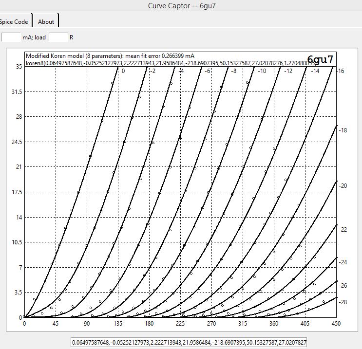
* Modified Koren model (8 parameters): mean fit error 0.26mA
* Traced by erik 25/12/2013 using Curve Captor v0.9.1
* from datasheet tracer
*
* 6gu7k8 LTSpice model
.subckt 6gu7k8 P G K
Bp P K I=(0.06497587648m)*uramp(V(P,K)*ln(1.0+(-0.05252127973)+exp((2.222713943)+(2.222713943)*((21.9586484)+(-218.6907395m)*V(G,K))*V(G,K)/sqrt((50.15327587)**2+(V(P,K)-(27.02078276))**2)))/(2.222713943))**(1.270480055)
Cgk G K 3.6p ; 0.2p added
Cpk P K 4p ; 0.5p added
Cgp G P 3.5p ; 0.5p added
Rpk P K 1G ; to avoid floating nodes
d3 G K dx1
.model dx1 d(is=1n rs=2k cjo=1pf N=1.5 tt=1n)
.ends
* LTSpice model
* Modified Koren model (8 parameters): mean fit error 0.26mA
* Traced by erik 25/12/2013 using Curve Captor v0.9.1
* from datasheet tracer
*
* 6gu7k8 LTSpice model
.subckt 6gu7k8 P G K
Bp P K I=(0.06497587648m)*uramp(V(P,K)*ln(1.0+(-0.05252127973)+exp((2.222713943)+(2.222713943)*((21.9586484)+(-218.6907395m)*V(G,K))*V(G,K)/sqrt((50.15327587)**2+(V(P,K)-(27.02078276))**2)))/(2.222713943))**(1.270480055)
Cgk G K 3.6p ; 0.2p added
Cpk P K 4p ; 0.5p added
Cgp G P 3.5p ; 0.5p added
Rpk P K 1G ; to avoid floating nodes
d3 G K dx1
.model dx1 d(is=1n rs=2k cjo=1pf N=1.5 tt=1n)
.ends
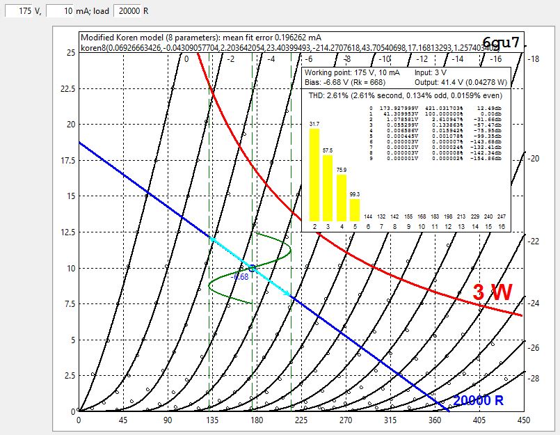
Removed data above 3W. better fit for low currents
* 6gu7 LTSpice model
.subckt 6gu7 P G K
Bp P K I=(0.06926663426m)*uramp(V(P,K)*ln(1.0+(-0.04309057704)+exp((2.203642054)+(2.203642054)*((23.40399493)+(-214.2707618m)*V(G,K))*V(G,K)/sqrt((43.70540698)**2+(V(P,K)-(17.16813293))**2)))/(2.203642054))**(1.257403402)
.ends 6gu7
6GU7 is my secret tube, drives my KT120 SET connected with very good resuts ( low overall distortion due to harmonic cancellation)
Last edited:
Anyone have a model for 6B4G tube?
Thanks
Mark
Isn't it equivalent to the 2A3?
6SN7 vs 6CG7 model
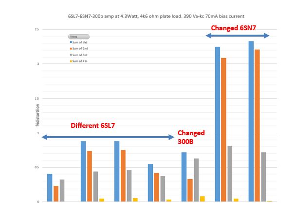
I just used a 6SN7 model and 6CG7 model on the same circuit and got different results. The DC analysis comes out almost identical, but not the AC. Huge difference in THD.
So, is is this a legit difference between the 2 types? And if not, can someone point me to models for the 2 types that have been verified (reasonably) accurate? Thanks.
Here's a quick comparison of my 6CG7 model and Ayumi's 6SN7. Black curves = 6CG7, red curves = Ayumi's 6SN7 model. But first a screenshot of my 6CG7 model in CurveCaptor. The dots (circles) are the actual traced curves from the GE datasheet.I can't remember for sure, I added them to my library a while back.
That's why I'm asking for "known good" models.
Edit: Forgot that they're labelled. One is Ayumi, the other is a modified Koren by Wayne Clay.
I've noticed that different timestep values in a simulation can give differing THD levels, especially from the Ayumi models... One reason I don't give much weight to THD simulation results. Add a little salt.
")
Real tubes will never align perfectly with published curves and will measure differently in actual circuits. All we can hope for is reasonably accurate models.
Attachments
Cogs, if you're Wayne, I have it the other way around, I have a CG7 by Ayumi and SN7 by Wayne Clay. Regardless, doesn't matter, thanks for posting that info, I'd like to use the Wayne version. Can you verify that this is correct? Thanks much
* 6SN7_GE LTSpice model
* Modified Koren model (8 parameters): mean fit error 0.0771164mA
* Traced by Wayne Clay on 10/11/2013 using Curve Captor v0.9.1
* from General Elctric data sheet
.subckt 6SN7_GE P G K
Bp P K I=
+ (0.01996138472m)*uramp(V(P,K)*ln(1.0+(-0.06003194624)+exp((4.721146098)+
+ (4.721146098)*((20.78010878)+(-111.9910206m)*V(G,K))*V(G,K)/sqrt((29.06231184)**2+
+ (V(P,K)-(6.821890538))**2)))/(4.721146098))**(1.378722311)
Cgk G K 2.8p ; 0.2p added
Cpk P K 2.2p ; 0.5p added
Cgp G P 4.5p ; 0.5p added
Rpk P K 1G ; to avoid floating nodes
d3 G K dx1
.model dx1 d(is=1n rs=2k cjo=1pf N=1.5 tt=1n)
.ends
6SN7_GE:Cogs, if you're Wayne, I have it the other way around, I have a CG7 by Ayumi and SN7 by Wayne Clay. Regardless, doesn't matter, thanks for posting that info, I'd like to use the Wayne version. Can you verify that this is correct? Thanks much
Code:
* 6SN7_GE LTSpice model
* Modified Koren model (8 parameters): mean fit error 0.0771164mA
* Traced by Wayne Clay on 10/11/2013 using Curve Captor v0.9.1
* from General Elctric data sheet
.subckt 6SN7_GE P G K
Bp P K I=
+ (0.01996138472m)*uramp(V(P,K)*ln(1.0+(-0.06003194624)+exp((4.721146098)+
+ (4.721146098)*((20.78010878)+(-111.9910206m)*V(G,K))*V(G,K)/sqrt((29.06231184)**2+
+ (V(P,K)-(6.821890538))**2)))/(4.721146098))**(1.378722311)
Cgk G K 2.8p ; 0.2p added
Cpk P K 2.2p ; 0.5p added
Cgp G P 4.5p ; 0.5p added
Rpk P K 1G ; to avoid floating nodes
d3 G K dx1
.model dx1 d(is=1n rs=2k cjo=1pf N=1.5 tt=1n)
.ends 6SN7_GE
Code:
* 6CG7_GE LTSpice model
* Modified Koren model (8 parameters): mean fit error 0.0749904mA
* Traced by Wayne Clay on 10/03/2013 using Curve Captor v0.9.1
* from General Electric data sheet
.subckt 6CG7_GE  P G K
    Bp  P K  I=
+ (0.02053902262m)*uramp(V(P,K)*ln(1.0+(-0.06147138054)+exp((4.780357089)+
+ (4.780357089)*((20.90066891)+(-105.6185609m)*V(G,K))*V(G,K)/sqrt((23.56820043)**2+
+ (V(P,K)-(4.933537229))**2)))/(4.780357089))**(1.37367599)
  Cgk G K 3.0p ; 0.7p added
  Cpk P K 2.7p ; 0.5p added
  Cgp G P 4.7p ; 0.7p added
  Rpk P K 1G   ; to avoid floating nodes
  d3  G K dx1
.model dx1 d(is=1n rs=2k cjo=1pf N=1.5 tt=1n)
.ends 6CG7_GECheers from Wayne in Wayne County.

Thanks Wayne.
General question: If I understand it correctly, there are specialized tube "testers" out there capable of running curves and then generating a model from those. Is this true? If so, does anyone have a link to manufacturers, etc. or even just an article so I can read up on this?
Also, does anyone offer this as a service?
Real tubes will never align perfectly with published curves and will measure differently in actual circuits. All we can hope for is reasonably accurate models.
Agreed. I'm not worried about small differences, but some differences are very large and that kind of makes the whole simulation concept worthless. I've had some pretty large differences in AC signal levels as well as THD. I'm thinking it would be a good idea for authors to put in the notes inside the model what was used for curves: what tube manufacturer, actual tube measurement or published curves, etc. Would narrow down the variability to manageable levels, hopefully
Thanks Wayne.
General question: If I understand it correctly, there are specialized tube "testers" out there capable of running curves and then generating a model from those. Is this true? If so, does anyone have a link to manufacturers, etc. or even just an article so I can read up on this?
Also, does anyone offer this as a service?
uTracer? Ronald's electronic project site
I built one to do just that, so I can model the actual tubes I will be using. It's a quick and easy way of generating models. If you use the Derk Reefman's "Extractmodel" you get Koren & Derk parameters for your tube. You can also chose the measurement range to get a best fit for your tube operating conditions so you can do some optimisation that way.
I have done some parameter extraction for folks who have sent me tubes to measure, it's not a "service" but I am happy to do it FOC because that way I get to learn more about tubes
5654/6AK5/6J1 SPICE Models
Triode-Connected
Pentode
Triode-Connected
Code:
*
* Generic triode model: 5654_T_AN
* Copyright 2003--2008 by Ayumi Nakabayashi, All rights reserved.
* Version 3.10, Generated on Wed Feb 03 16:25:08 2016
*                 Plate
*                 | Grid
*                 | | Cathode
*                 | | |
.SUBCKT 5654_T_AN A G K
BGG   GG   0 V=V(G,K)+0.2564934
BM1   M1   0 V=(0.020250832*(URAMP(V(A,K))+1e-10))**-1.0936778
BM2   M2   0 V=(0.57832935*(URAMP(V(GG)+URAMP(V(A,K))/20.822386)+1e-10))**2.5936778
BP    P    0 V=0.0042701484*(URAMP(V(GG)+URAMP(V(A,K))/36.004374)+1e-10)**1.5
BIK   IK   0 V=U(V(GG))*V(P)+(1-U(V(GG)))*0.0030226533*V(M1)*V(M2)
BIG   IG   0 V=0.0021350742*URAMP(V(G,K))**1.5*(URAMP(V(G,K))/(URAMP(V(A,K))+URAMP(V(G,K)))*1.2+0.4)
BIAK  A    K I=URAMP(V(IK,IG)-URAMP(V(IK,IG)-(0.002314205*URAMP(V(A,K))**1.5)))+1e-10*V(A,K)
BIGK  G    K I=V(IG)
* CAPS
CGA   G    A 0.02p
CGK   G    K 4.3p
CAK   A    K 2.4p
.ENDS
Pentode
Code:
*
* Generic pentode model: 5654_AN
* Copyright 2003--2008 by Ayumi Nakabayashi, All rights reserved.
* Version 3.10, Generated on Wed Feb 03 16:24:50 2016
*               Plate
*               | Screen Grid
*               | |  Control Grid
*               | |  |  Cathode
*               | |  |  |
.SUBCKT 5654_AN A G2 G1 K
BGG   GG   0 V=V(G1,K)+0.2564934
BM1   M1   0 V=(0.020250832*(URAMP(V(G2,K))+1e-10))**-1.0936778
BM2   M2   0 V=(0.57832935*(URAMP(V(GG)+URAMP(V(G2,K))/20.822386)))**2.5936778
BP    P    0 V=0.0042701484*(URAMP(V(GG)+URAMP(V(G2,K))/36.004374))**1.5
BIK   IK   0 V=U(V(GG))*V(P)+(1-U(V(GG)))*0.0030226533*V(M1)*V(M2)
BIG   IG   0 V=0.0021350742*URAMP(V(G1,K))**1.5*(URAMP(V(G1,K))/(URAMP(V(A,K))+URAMP(V(G1,K)))*1.2+0.4)
BIK2  IK2  0 V=V(IK,IG)*(1-0.4*(EXP(-URAMP(V(A,K))/URAMP(V(G2,K))*15)-EXP(-15)))
BIG2T IG2T 0 V=V(IK2)*(0.76634978*(1-URAMP(V(A,K))/(URAMP(V(A,K))+10))**1.5+0.23365022)
BIK3  IK3  0 V=V(IK2)*(URAMP(V(A,K))+3705)/(URAMP(V(G2,K))+3705)
BIK4  IK4  0 V=V(IK3)-URAMP(V(IK3)-(0.002314205*(URAMP(V(A,K))+URAMP(URAMP(V(G2,K))-URAMP(V(A,K))))**1.5))
BIP   IP   0 V=URAMP(V(IK4,IG2T)-URAMP(V(IK4,IG2T)-(0.002314205*URAMP(V(A,K))**1.5)))
BIAK  A    K I=V(IP)+1e-10*V(A,K)
BIG2  G2   K I=URAMP(V(IK4,IP))
BIGK  G1   K I=V(IG)
* CAPS
CGA   G1  A  0.02p
CGK   G1  K  2.6p
C12   G1  G2 1.7p
CAK   A   K  2.4p
.ENDSYes , who is willing to utrace it for me?It could be just an one-off coincidence due to the tolerance of the tube. Perhaps you can send your tube to get traced if you are really interested in its characteristics.
Best regards
Balle
- Home
- Amplifiers
- Tubes / Valves
- Vacuum Tube SPICE Models