You are welcome, Bea.(...)
So thank You for the model, dear Adrian, and all for the help.
And sorry that it was a bit quiet from my side, I had a lot to do.
Hi,
Does anyone know where I can find the derivation of the extended Koren tube models? I see "koren4", "koren5", "koren6" and "koren8" in the source of curve captor, and though I can sorta reverse-engineer the math from the source code, I'd rather see the original derivation to make sure I'm not blindly copying without understanding.
For context, I'm making my own completely open-source version of vtadiy.com's loadline calculator. I've already got it working with the original Koren model and also with the Ayumi model (both for triodes, working on pentodes now). It looks very much like the vtadiy.com version, but adds a few features that I need for my own projects (fixed and cathode bias modes, cathode load field, calculating output headroom from input headroom, multiple models). And since it will be open source, anyone will be free to submit bug reports or PRs, or even fork the repo and do whatever they want. Here's a screenshot:

Tech details: written in modern Javascript using Vue.js and Chart.js (same chart library the vtadiy.com version uses). It's built to be extensible, so adding new models, curves, or types of tubes is pretty straightforward (basically just extend a class). I'm not quite ready to put it up on github yet, but I think I'm only a few weeks away. It has no server dependency, so I'm going to host it on github.io.
thanks!
Does anyone know where I can find the derivation of the extended Koren tube models? I see "koren4", "koren5", "koren6" and "koren8" in the source of curve captor, and though I can sorta reverse-engineer the math from the source code, I'd rather see the original derivation to make sure I'm not blindly copying without understanding.
For context, I'm making my own completely open-source version of vtadiy.com's loadline calculator. I've already got it working with the original Koren model and also with the Ayumi model (both for triodes, working on pentodes now). It looks very much like the vtadiy.com version, but adds a few features that I need for my own projects (fixed and cathode bias modes, cathode load field, calculating output headroom from input headroom, multiple models). And since it will be open source, anyone will be free to submit bug reports or PRs, or even fork the repo and do whatever they want. Here's a screenshot:
Tech details: written in modern Javascript using Vue.js and Chart.js (same chart library the vtadiy.com version uses). It's built to be extensible, so adding new models, curves, or types of tubes is pretty straightforward (basically just extend a class). I'm not quite ready to put it up on github yet, but I think I'm only a few weeks away. It has no server dependency, so I'm going to host it on github.io.
thanks!
Koren's last work before shifting to photography appears dated 2003. Are the extensions created by others?
https://www.normankoren.com/Audio/Tubemodspice_article.html
https://www.normankoren.com/Audio/Tubemodspice_article.html
Wayne Clay ("cogsncogs") posted a model of the triode section of the 6AW8 tube on the Intact Audio forum some time ago; see link below.Does anybody have models for triode and pentode of 6AW8A?
https://forum.intactaudio.com/viewtopic.php?f=15&t=1429
He is also a member here on diyAudio so maybe he can help with a model for the pentode section.
It seems so. Both CurveCaptor and PaintKIT.jar seem to use models that extend Koren's original work. But Google hasn't helped me find the source of their extended models.Koren's last work before shifting to photography appears dated 2003. Are the extensions created by others?
https://www.normankoren.com/Audio/Tubemodspice_article.html
e.g. the comments in PaintKIT/PaintKIP.java:
,synopsis1 = "Generates Koren Improved Pentode SPICE models,"
,__synopsis_2_ = " with a number of extensions and enhancements (knee shape, tetrode kink)"
and in CurveCaptor's tubefit.c:
/* Vacuum triode models */
[...]
{3, "Koren model (4 parameters)", "koren4", 4, triode_koren4, init_koren4},
{3, "Koren model (5 parameters)", "koren5", 5, triode_koren5, init_koren5},
{3, "Modified Koren model (6 parameters)", "koren6", 6, triode_koren6, init_koren6},
{3, "Modified Koren model (8 parameters)", "koren8", 8, triode_koren8, init_koren8},
cheers,
-Mark
Can't wait to see it online....Hi,
Does anyone know where I can find the derivation of the extended Koren tube models? I see "koren4", "koren5", "koren6" and "koren8" in the source of curve captor, and though I can sorta reverse-engineer the math from the source code, I'd rather see the original derivation to make sure I'm not blindly copying without understanding.
For context, I'm making my own completely open-source version of vtadiy.com's loadline calculator. I've already got it working with the original Koren model and also with the Ayumi model (both for triodes, working on pentodes now). It looks very much like the vtadiy.com version, but adds a few features that I need for my own projects (fixed and cathode bias modes, cathode load field, calculating output headroom from input headroom, multiple models). And since it will be open source, anyone will be free to submit bug reports or PRs, or even fork the repo and do whatever they want. Here's a screenshot:
View attachment 1270814
Tech details: written in modern Javascript using Vue.js and Chart.js (same chart library the vtadiy.com version uses). It's built to be extensible, so adding new models, curves, or types of tubes is pretty straightforward (basically just extend a class). I'm not quite ready to put it up on github yet, but I think I'm only a few weeks away. It has no server dependency, so I'm going to host it on github.io.
thanks!
I am working on a project for a direct drive amplifier for electrostatic speakers.
The current amplifier works fine but has a bit too low output voltage (using 6HS5 tubes).
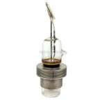
I have obtained some GI-17 high voltage triodes for the next version, doubling Vout.
I really would like to run some LTspice sims on the new design, but, as you can imagine, there's no model for the GI-17.
Is there anyone who can (and is willing) to devise an LTspice model for the GI-17?
I will use it with max 60mA Ia and 4kV Vak, so only that area needs to be modelled; I do not expect to get into grid current.
My prelim measurements show this:
Vak 1kV
Vgk Ia
-63V 10mA
-55V 20mA
-50V 30mA
Vak 2kV
Vgk Ia
-130V 10mA
-116V 20mA
-107V 30mA
I can offer a Linear Audio USB stick as compensation.
Jan
The current amplifier works fine but has a bit too low output voltage (using 6HS5 tubes).
I have obtained some GI-17 high voltage triodes for the next version, doubling Vout.
I really would like to run some LTspice sims on the new design, but, as you can imagine, there's no model for the GI-17.
Is there anyone who can (and is willing) to devise an LTspice model for the GI-17?
I will use it with max 60mA Ia and 4kV Vak, so only that area needs to be modelled; I do not expect to get into grid current.
My prelim measurements show this:
Vak 1kV
Vgk Ia
-63V 10mA
-55V 20mA
-50V 30mA
Vak 2kV
Vgk Ia
-130V 10mA
-116V 20mA
-107V 30mA
I can offer a Linear Audio USB stick as compensation.
Jan
Attachments


Hi Jan
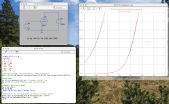
I fitted a simple model to the measured data you provided, see graph attached.
BUT !!
As one can see, the contact voltage Vct is decades away from the typical range of 0 ... 1 V.
Hence, I strongly suppose that there is something wrong. So, here some questions:
1) did you notice thermal drift (unstable current) of your measured tube?
2) Did you perhaps connect the wrong filament pin to the GND?
BR Adrian
Attachments
Hello,
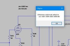
Hope I'm not beating a dead horse here...but this one has got me perplexed! I unzipped the Ayumi tube models (Ayumi_LTspice.zip) to a folder, and added that directory to the paths in "options". I'm using 2 tubes, 6SN7 and 6L6. The 6SN7 is fine, using the stock LTSpice triode symbol. For the 6L6 I am using the tetrode symbol as suggested in a few places here. I checked the symbol; it appears to be connected OK, yet LTSpice is complaining about the 6L6, and not the 6SN7. Cannot make any sense out of this. See attached screen cap.
Any suggestions?
Attachments
Hi Adrian, thank you so much!
I will be away tomorrow but will investigate Tuesday.
What do you mean by contact voltage? Is that Vgk?
I noticed no drift but my tests were short, I had no time but just wanted to check that the tube wasn't dead.
I have more tubes to verify.
The heater was 5.5V DC so in light of the Vgk tested I don't think it matters which side is grounded, but I will check.
Jan
Here are the contents of the 6L6.inc file. Note that the model name is "6L6_AN" and not just "6L6" as @jcalvarez suspected. The instance name on the schematic must match the SUBCKT name in the SPICE model file. So you need to change either the instance name on the schematic to "6L6_AN" or rename the SUBCKT to "6L6."
Code:
*
* Generic pentode model: 6L6
* Copyright 2003--2008 by Ayumi Nakabayashi, All rights reserved.
* Version 3.10, Generated on Sat Mar  8 22:40:38 2008
*              Plate
*              | Screen Grid
*              | |  Control Grid
*              | |  |  Cathode
*              | |  |  |
.SUBCKT 6L6_AN A G2 G1 K
BGG   GG   0 V=V(G1,K)+0.91804059
BM1   M1   0 V=(0.10751078*(URAMP(V(G2,K))+1e-10))**-1.743575
BM2   M2   0 V=(0.4624527*(URAMP(V(GG)+URAMP(V(G2,K))/4.9999386)))**3.243575
BP    P    0 V=0.0016883841*(URAMP(V(GG)+URAMP(V(G2,K))/10.811784))**1.5
BIK   IK   0 V=U(V(GG))*V(P)+(1-U(V(GG)))*0.0021948901*V(M1)*V(M2)
BIG   IG   0 V=0.0022135943*URAMP(V(G1,K))**1.5*(URAMP(V(G1,K))/(URAMP(V(A,K))+URAMP(V(G1,K)))*1.2+0.4)
BIK2  IK2  0 V=V(IK,IG)*(1-0.4*(EXP(-URAMP(V(A,K))/URAMP(V(G2,K))*15)-EXP(-15)))
BIG2T IG2T 0 V=V(IK2)*(0.942171668*(1-URAMP(V(A,K))/(URAMP(V(A,K))+10))**1.5+0.057828332)
BIK3  IK3  0 V=V(IK2)*(URAMP(V(A,K))+2180)/(URAMP(V(G2,K))+2180)
BIK4  IK4  0 V=V(IK3)-URAMP(V(IK3)-(0.00056920996*(URAMP(V(A,K))+URAMP(URAMP(V(G2,K))-URAMP(V(A,K))))**1.5))
BIP   IP   0 V=URAMP(V(IK4,IG2T)-URAMP(V(IK4,IG2T)-(0.00056920996*URAMP(V(A,K))**1.5)))
BIAK  A    K I=V(IP)+1e-10*V(A,K)
BIG2  G2   K I=URAMP(V(IK4,IP))
BIGK  G1   K I=V(IG)
* CAPS
CGA   G1  A  0.6p
CGK   G1  K  5.7p
C12   G1  G2 3.8p
CAK   A   K  5.9p
.ENDS
Last edited:
Thanks! Ok, that was the problem! Now, I see it doesn't work the same as it did before. I created this about 10 years ago, and used Norman Koren's tube.lib file. At that time LTSpice had a symbol called "pentode2" which is what I used, and it was working just fine. Now it doesn't seem to work with the new 6L6 (6SN7 ok) it has very limited drive. I'll keep at it and report back a bit later when I've run out of ideas...again. 
The Koren tetrode models use a different pin order which is not compatible with the built-in LTspice tetrode symbol. Koren models use the pin order P G1 K G2, whereas LTspice uses the pin order P G2 G1 K.
It's easy to get tripped up by this. You can create a special Koren-type symbol in LTspice if you want to continue using the Koren model, or you can modify the Koren model pin order to match the LTspice tetrode symbol. But the point is that the symbol pin order must match the pin order of the SUBCKT.
It's easy to get tripped up by this. You can create a special Koren-type symbol in LTspice if you want to continue using the Koren model, or you can modify the Koren model pin order to match the LTspice tetrode symbol. But the point is that the symbol pin order must match the pin order of the SUBCKT.
Hi Ray -
Thanks again for the helpful feedback. Went back to the tetrode symbol and Ayumi model.
Now getting closer! I had the cathode feedback taps wired to the OPT wrong, so now getting output again. However, the power is low - with 1 volt at input there should be about 17 volts into 8 ohm load, but only getting 9. Will need to fiddle about some more.
UPDATE - Now working 100%, yet another wiring error. I must have been gooned out or something last time I touched these, because there were 2 key wiring errors. No matter, all is well now!
Last edited:
Good morning Adrian,Hi Jan
I fitted a simple model to the measured data you provided, see graph attached.
BUT !!
As one can see, the contact voltage Vct is decades away from the typical range of 0 ... 1 V.
Hence, I strongly suppose that there is something wrong. So, here some questions:
1) did you notice thermal drift (unstable current) of your measured tube?
2) Did you perhaps connect the wrong filament pin to the GND?
BR Adrian
Could you attach the original .asc and the model as text file?
I'm sure I will make an error retyping the model figures ...
Jan
- Home
- Amplifiers
- Tubes / Valves
- Vacuum Tube SPICE Models