I think that will be true for anyone who assembles a library for their own purposes. I'd share my own library except that I know I would get inundated with requests for models that I didn't choose to include in it. Maintaining such a library would be an endless (and probably thankless) task. 
I do exactly that, googling does tbe job for me.Although this might seem like a good idea at first, it is not a practical one for several reasons. First, there are many approaches to modeling tubes so there are going to be several postings here for the same tube type, especially for the more common tubes. You would need to create a model naming scheme that would differentiate between, for example, a Koren model and an Ayumi model for the same tube unless you are going to choose only one model for each tube type. Second, some of the models posted here were found to have a problem that was corrected in a later posting, so you would need to search backward in time to make sure to get the latest model. And third, some tubes are referred to by more than one name, like the 12AX7 and ECC83, so you would need to account for this to avoid possibly having redundant or conflicting models in your library.
I have built a personal tube library taking these issues into account but I don't see the need to include every known tube model in that library. My library just includes the tubes that I might actually design with. I do have different models for the same tube so that I can verify that a simulation looks valid with other than just one model. This is helpful because some models might not behave well in a particular circuit.
When the need arises for a model that I don't already have, I'll search here first and then do a more general Internet search. That to me is more practical than trying to build a complete library of tube models just for the sake of having a complete set. My suggestion is to build your own library over time. That way, you will know exactly what is in it.
Just my opinions, of course.
Just to better explain my point: all models would be shared here for free as it is now. If someone wants to build its own set of models can do it for free. Is someone wants all the models ready to be used, a small donation to the forum (so that everyon can benefit of the forum) can be done.
@qiuchun63 FYI, Koonw membership has been disabled.
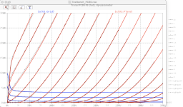
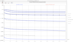
Make sure "Kink" is checked. Aviod using "Advance Knee" if you can. The screen current is too high, need to adjust before it can be used.
Code:**** 6418P ****************************************** * Created on 05/04/2023 22:50 using paint_kip.jar * www.dmitrynizh.com/tubeparams_image.htm * Plate Curves image file: 6418p.jpg * Data source link: <plate curves URL> *---------------------------------------------------------------------------------- .SUBCKT 6418P P G2 G K ; LTSpice tetrode.asy pinout * .SUBCKT 6418P P G K G2 ; Koren Pentode Pspice pinout + PARAMS: MU=10.41 KG1=17952 KP=33.97 KVB=0.225 VCT=0.018 EX=1.484 KG2=1123.5 KNEE=4.464 KVC=2.57 + KLAM=7.187E-9 KLAMG=0.006 KNEE2=3.4 KNEX=568.8 KNK=-0.044 KNG=0.006 KNPL=50 KNSL=11 KNPR=120 KNSR=29 + CCG=3P CGP=1.4P CCP=1.9P RGI=2000.0 * Vp_MAX=60 Ip_MAX=0.8 Vg_step=0.4 Vg_start=0 Vg_count=7 * X_MIN=162 Y_MIN=231 X_SIZE=548 Y_SIZE=377 FSZ_X=1296 FSZ_Y=736 XYGrid=true * Rp=1400 Vg_ac=20 P_max=0.2 Vg_qui=-1.2 Vp_qui=300 * showLoadLine=n showIp=y isDHP=n isPP=n isAsymPP=n isUL=n showDissipLimit=y * showIg1=n isInputSnapped=y addLocalNFB=n * XYProjections=n harmonicPlot=y dissipPlot=n * UL=0.43 EG2=22.5 gridLevel2=n addKink=y isTanhKnee=y advSigmoid=n *---------------------------------------------------------------------------------- RE1 7 0 1G ; DUMMY SO NODE 7 HAS 2 CONNECTIONS E1 7 0 VALUE= ; E1 BREAKS UP LONG EQUATION FOR G1. +{V(G2,K)/KP*LOG(1+EXP((1/MU+(VCT+V(G,K))/SQRT(KVB+V(G2,K)*V(G2,K)))*KP))} RE2 6 0 1G ; DUMMY SO NODE 6 HAS 2 CONNECTIONS E2 6 0 VALUE={(PWR(V(7),EX)+PWRS(V(7),EX))} ; Kg1 times KIT current RE21 21 0 1 E21 21 0 VALUE={V(6)/KG1*ATAN((V(P,K)+KNEX)/KNEE)*TANH(V(P,K)/KNEE2)} ; Ip with knee but no slope and no kink RE22 22 0 1 ; E22: kink curr deviation for plate E22 22 0 VALUE={V(21)*LIMIT(KNK-V(G,K)*KNG,0,0.3)*(-ATAN((V(P,K)-KNPL)/KNSL)+ATAN((V(P,K)-KNPR)/KNSR))} G1 P K VALUE={V(21)*(1+KLAMG*V(P,K))+KLAM*V(P,K) + V(22)} * Alexander Gurskii screen current, see audioXpress 2/2011, with slope and kink added RE43 43 K 1G ; Dummy E43 43 G2 VALUE={0} ; Dummy G2 43 K VALUE={V(6)/KG2*(KVC-ATAN((V(P,K)+KNEX)/KNEE)*TANH(V(P,K)/KNEE2))/(1+KLAMG*V(P,K))-V(22)} RCP P K 1G ; FOR CONVERGENCE C1 K G {CCG} ; CATHODE-GRID 1 C2 G P {CGP} ; GRID 1-PLATE C3 K P {CCP} ; CATHODE-PLATE R1 G 5 {RGI} ; FOR GRID CURRENT D3 5 K DX ; FOR GRID CURRENT } .MODEL DX D(IS=1N RS=1 CJO=10PF TT=1N) .ENDS *$
Which is a pity, he was very helpful, created and shared many, many models, many of which I use. I hope he comes back to the forum one day 🤞@qiuchun63 FYI, Koonw membership has been disabled.
6211 MODE
** 6211 ****************************************
.SUBCKT 6211 1 2 3 ; Plate Grid Cathode
E1 7 0 VALUE={V(1,3)/KP*LN(1+EXP(KP*(1/MU+(VCT+V(2,3))/SQRT(KVB+V(1,3)*V(1,3)))))}
RE1 7 0 1G ; TO AVOID FLOATING NODES
G1 1 3 VALUE={(PWR(V(7),EX)+PWRS(V(7),EX))/KG1}
RCP 1 3 1G ; TO AVOID FLOATING NODES
C1 2 3 {CCG} ; CATHODE-GRID
C2 2 1 {CGP} ; GRID=PLATE
C3 1 3 {CCP} ; CATHODE-PLATE
D3 5 3 DX ; POSITIVE GRID CURRENT
R1 2 5 {RGI} ; POSITIVE GRID CURRENT
.MODEL DX D(IS=1N RS=1 CJO=10PF TT=1N)
.ENDS
*$
** 6211 ****************************************
- Created on 11/09/2023 09:36 using paint_kit.jar 3.1
- www.dmitrynizh.com/tubeparams_image.htm
- Plate Curves image file:
- Data source link:
.SUBCKT 6211 1 2 3 ; Plate Grid Cathode
- PARAMS: CCG=2.9P CGP=2.22P CCP=0.54P RGI=2000
- MU=38.98 KG1=480 KP=100 KVB=603 VCT=0.28 EX=1.372
- Vp_MAX=400 Ip_MAX=40 Vg_step=1 Vg_start=0 Vg_count=7
- Rp=4000 Vg_ac=55 P_max=1 Vg_qui=-48 Vp_qui=300
- X_MIN=94 Y_MIN=25 X_SIZE=719 Y_SIZE=720 FSZ_X=1936 FSZ_Y=1056 XYGrid=false
- showLoadLine=n showIp=y isDHT=n isPP=n isAsymPP=n showDissipLimit=y
- showIg1=n gridLevel2=n isInputSnapped=n
- XYProjections=n harmonicPlot=n dissipPlot=n
E1 7 0 VALUE={V(1,3)/KP*LN(1+EXP(KP*(1/MU+(VCT+V(2,3))/SQRT(KVB+V(1,3)*V(1,3)))))}
RE1 7 0 1G ; TO AVOID FLOATING NODES
G1 1 3 VALUE={(PWR(V(7),EX)+PWRS(V(7),EX))/KG1}
RCP 1 3 1G ; TO AVOID FLOATING NODES
C1 2 3 {CCG} ; CATHODE-GRID
C2 2 1 {CGP} ; GRID=PLATE
C3 1 3 {CCP} ; CATHODE-PLATE
D3 5 3 DX ; POSITIVE GRID CURRENT
R1 2 5 {RGI} ; POSITIVE GRID CURRENT
.MODEL DX D(IS=1N RS=1 CJO=10PF TT=1N)
.ENDS
*$

- PC86 LTSpice model
- Modified Koren model (8 parameters): mean fit error 0.236785mA
- Traced by Wayne Clay using Engauge digitizer and Curve Captor v0.9.1
- from Philips data sheet on 03/15/15
Bp P K I=(0.05674911911m)uramp(V(P,K)*ln(1.0+(0.05345394339)+exp((8.525091362)+(8.525091362)((61.30204868)+(-2561.853454m)V(G,K))V(G,K)/sqrt((28.93128599)**2+(V(P,K)-(8.58346366))**2)))/(8.525091362))(1.24465797)
Cgp G P 2.1p ; 0.7p added
Cgk G K 1.9p ; 0.7p added
Cpk P K 2.0p ; 0.5p added
Rpk P K 1G ; to avoid floating nodes
d3 G K dx1
.model dx1 d(is=1n rs=2k cjo=1pf N=1.5 tt=1n)
.ends PC86
Hi Sorento
Here an alternative PC86 model of mine...
BR Adrian
Here an alternative PC86 model of mine...
BR Adrian
Code:
*PC86 LTspice model based on the generic triode model from Adrian Immler, version i6
*A version log is at the end of this file
*100h BurnIn of 10 Tronal tubes, sample selection and measurements done in April 2023
*Params fitted to the measured values by Adrian Immler, November 2023
*This model is accurate for Vg up to 1.5V.
*The fit quality is presented at adrianimmler.simplesite.com
*History's best of tube describing art (plus some new ideas) is merged to this new approach.
*@ neg. Vg, Ia accuracy is similar to Koren models, and unrivaled for remote cutoff triodes
*@ small neg. Vg, the "Anlauf" current is considered.
*@ pos. Vg, Ig and Ia accuracy is on an unrivaled level (including neg. Va range!)
*This offers new simulation possibilities like grid resistor bias, backward plate modulated stages,
*Audion radio circuits, low voltage amps, guitar distortion stages or pulsed stages.
*It is assumed that there exists only 1 construction version of the PC86 (3 different brands seen so far)
*Hence, the two letters for the brand are skipped.
*            i6 version is identical to the i5, but measurements done with HOT anode for highest accuracy
*            |  anode (plate)
*            |  | grid
*            |  | | cathode
*            |  | | |
.subckt PC86.i6 A G K
+ params:
*Parameters for space charge current Is (100% assigned to Ia @ Vg < 0)
+ mu   = 64.1  ;Determines the voltage gain @ constant Ia
+ rad  = 3k3   ;Differential anode resistance, set @ Iad and Vg=0V
+ Vct  = 0.1   ;Offsets the Ia-traces on the Va axis. Electrode material's contact potential
+ kp   = 500   ;Mimics the island effect
+ xs   = 1.5   ;Determines the curve of the Ia traces. Typically between 1.2 and 1.8
+ kIsr = 30m   ;Va-indepedent part of the Is reduction when gridcurrent occurs
+ kvdg  = 95   ;Va-depedent part of the Is reduction when gridcurrent occurs
*
*Parameters for assigning the space charge current to Ia and Ig @ Vg > 0
+ kB   = 1.0   ;Describes how fast Ia drops to zero when Va approaches zero.
+ radl = 320   ;Differential resistance for the Ia emission limit @ very small Va and Vg > 0
+ tsh  = 8     ;Ia transmission sharpness from 1th to 2nd Ia area. Keep between 3 and 20. Start with 20.
+ xl   = 1.5   ;Exponent for the emission limit
*
*Parameters of the grid-cathode vacuum diode
+ kg = 400     ;Inverse scaling factor for the Va independent part of Ig (caution - interacts with xg!)
+ Vctg = -0.25 ;Offsets the log Ig-traces on the Vg axis. Electrode material's contact potential
+ xg   = 1.3   ;Determines the curve of the Ig slope versus (positive) Vg and Va >> 0
+ VT   = 0.11  ;Log(Ig) slope @ Vg<0. VT=k/q*Tk (cathodes absolute temp, typically 1150K)
+ rTr  = 0.72  ;ratio of VT for Igr. Typically 0.8
+ kVT  = 5m    ;Va dependant koeff. of VT
+ gft1 = 0.02  ;reduces the steering voltage around Vg=-Vg0, for finetuning purposes
+ gft1a= 0.2   ;reduces the steering voltage around Vg=-Vg0. Effect decreases with 1/(1+kB*Va)
+ gft2 = 0     ;finetunes the Igr drop @ incrasing Va and around Vg=-Vg0
*
*Parameters for the caps
+ cag  = 2p2   ;From datasheet
+ cak  = 0p24  ;From datasheet
+ cgk  = 3p5   ;From datasheet
*
*special purpose parameters
+ os = 1       ;Overall scaling factor, if a user wishes to simulate manufacturing tolerances
+ murc = 10    ;Mu of the remote cutoff triode
+ ksrc = 10G   ;Inverse Iarc gain factor for the remote cuttoff triode
+ kprc = 1k    ;Mimics the island effect for the remote cotoff triode
+ Vbatt = 0    ;heater battery voltage for direct heated battery triodes
+ Vdrmax = 1   ;max voltage of internal Vg drop, for convergence improvements
*
*Calculated parameters
+ Iad = {100/rad} ;Ia where the anode a.c. resistance is set according to rad.
+ ks = {pow(mu/(rad*xs*Iad**(1-1/xs)),-xs)} ;Reduces the unwished xs influence to the Ia slope
+ ksnom = {pow(mu/(rad*1.5*Iad**(1-1/1.5)),-1.5)} ;Sub-equation for calculating Vg0
+ Vg0 = {Vct + (Iad*ks)**(1/xs) - (Iad*ksnom)**(2/3)} ;Reduces the xs influence to Vct.
+ kl = {pow(1/(radl*xl*Ild**(1-1/xl)),-xl)} ;Reduces the xl influence to the Ia slope @ small Va
+ Ild = {sqrt(radl)*1m} ;Current where the Il a.c. resistance is set according to radl.
*
*Space charge current model
Rak A K 100G ;avoids "floating net" errors
Bft   ft 0 V=1/(1+pow(2*abs(v(G,Ki)+Vg0),3)) ;an auxiliary voltage to finetune the triode around Vg=-Vg0
Bggi GGi 0 V=(v(Gi,Ki)+Vg0)*(1/(1+kIsr*max(0, v(G,Ki)+Vg0))) - gft1*v(ft) - gft1a*v(ft)/(1+kB*v(Ahc)) ;Effective internal grid voltage.
Bahc Ahc 0 V=uramp(v(A,Ki)) ;Anode voltage, hard cut to zero @ neg. value
Bst   St 0 V=uramp(max(v(GGi)+v(A,Ki)/(mu), v(A,Ki)/kp*ln(1+exp(kp*(1/mu+v(GGi)/(1+v(Ahc)))))));Steering volt.
Bs    Ai Ki I=os/ks*pow(v(St),xs) ;Langmuir-Childs law for the space charge current Is
*Bstrc Strc 0 V=uramp(max(v(GGi)+v(Ahc)/(murc), v(Ahc)/kprc*ln(1+exp(kprc*(1/murc+v(GGi)/(1+v(Ahc)))))));FOR REMOTE CUTOFF TUBES ONLY
*Bsrc   Ai Ki I=os/ksrc*pow(v(Strc),xs) ;FOR REMOTE CUTOFF TUBES ONLY
*
*Anode current limit @ small Va
.func smin(z,y,n) {pow(pow(z+1f, -n)+pow(y+1f, -n), -1/n)} ;Min-function with smooth trans.
.func ssmin(z,y,n) {min(min(z,y), smin(z*1.003,y*1.003,n))};smin-function which suppresses small residual differencies
Ra  A Ai 1
Bgl Gi A I=uramp(i(Ra)-ssmin(1/kl*pow(v(Ahc),xl),i(Ra),tsh)) ;Ia emission limit
*
*Grid model
Rgk G K 10G ;avoids "floating net" errors
Bvdg G Gi I=1/kvdg*pow(v(G,Gi),1.5) ;Reduces the internal effective grid voltage when Ig rises
Bcoh G Gi I=pow(uramp(v(G,Gi)-Vdrmax),2) ;A convergence help which softly limits the internal Vg voltage drop.
Rgip G Gi 1G ;avoids some warnings
.func fVT() {VT*exp(-kVT*sqrt(v(A,Ki)))}
.func Ivd(Vvd, kvd, xvd, VTvd)  {if(Vvd < 3, 1/kvd*pow(VTvd*xvd*ln(1+exp(Vvd/VTvd/xvd)),xvd), 1/kvd*pow(Vvd, xvd))} ;Vacuum diode function
Bgvd G Ki I=Ivd(v(G,Ki) + Vctg + min(0,v(A,Ki)/mu), kg/os, xg, fVT()) ;limits the internal Vg for convergence reasons
Bstn Stn 0 V=v(GGi)+min(0,v(A,Ki))/mu ;special steering voltage, sensitive to negative Anodevoltages only
Bgr Gi Ai I= ivd(v(Stn),ks/os, xs, rTr*fVT())/(1+(kB+v(ft)*gft2)*v(Ahc));Is reflection to grid when Va approaches zero
*Bgr Gi Ai I=(ivd(v(Stn),ks/os, xs, rTr*fVT())+os/ksrc*pow(v(GGi),xs))/(1+(kB+v(ft)*gft2)*v(Ahc));FOR REMOTE CUTOFF TUBES ONLY
Bs0 Ai Ki  I=uramp(ivd(v(Stn),ks/os, xs, rTr*fVT()) - os/ks*pow(v(Stn),xs))
Bbatt Ki K V=Vbatt/2 ;for battery heated triodes; Offsets the average cathode potential to the half heater battery voltage
*
*Caps
C1 A G {cag}
C2 A K {cak}
C3 G K {cgk}
.ends
*
*Version log
*i1 :Initial version
*i2 :Pin order changed to the more common order A G K (Thanks to Markus Gyger for his tip)
*i3 :bugfix of the Ivd-function: now also usable for larger Vvd
*i4: Rgi replaced by a virtual vacuum diode (better convergence). ft1 deleted (no longer needed)
;2 new prarams for Ig finetuning @ Va and Vg near zero. New overall skaling factor os for aging etc.
*i5: improved convergence performance. PosVg/NegVa area now correct. Also accurate now for remote cutoff triodes!
*i6: identical to the i5, but tubes measured with hot anode (Pa=0.7*Pmax) for highest accuracy
Attachments
Thanks, @euro21
however, I got error messages from LTspice which didn't like the dots in the comment lines and missing "asterisk" * signs in uramp statement;
here's the corrected version which seems to work now:
strange thing ... when I tied to copy / paste the corrected version from LTspice directly to the forum, the asterisks were missing again ...
... strange
Attachments
Last edited:
Thank you for that model @Adrian Immler! I did have datasheet-based ones, but now I also got yours, which I understand is based on real tube measurement.
Between the ".subckt" and ".ends" is the "working part", the comment lines can be omitted.Thanks, @euro21
however, I got error messages from LTspice which didn't like the dots in the comment lines and missing "asterisk" * signs in uramp statement;
here's the corrected version which seems to work now:
strange thing ... when I tied to copy / paste the corrected version from LTspice directly to the forum, the asterisks were missing again ...
... strange
If you have tube symbol that use "A G K" syntactic instead of "P G K", must to exchange each "P" to "A".
Adrian's version is more sophisticated, use it.
You are welcome, jcalvarez.Thank you for that model @Adrian Immler! I did have datasheet-based ones, but now I also got yours, which I understand is based on real tube measurement.
And yes, it is based on measurements. Even under hot conditions, indicated with i6.
Done with this thing here:
https://adrianimmler.simplesite.com/452104653/448264046
all the best
Adrian
Thanks, @euro21
however, I got error messages from LTspice which didn't like the dots in the comment lines and missing "asterisk" * signs in uramp statement;
here's the corrected version which seems to work now:
strange thing ... when I tied to copy / paste the corrected version from LTspice directly to the forum, the asterisks were missing again ...
... strange
Code:
* ==============================================================
* PC86 LTSpice model
* Modified Koren model (8 parameters): mean fit error 0.236785mA
* Traced by Wayne Clay using Engauge digitizer and Curve Captor v0.9.1
* from Philips data sheet on 03/15/15
* ==============================================================
.subckt PC86  P G K
    Bp  P K  I=
+ (0.05674911911m)*uramp(V(P,K)*ln(1.0+(0.05345394339)+exp((8.525091362)+
+ (8.525091362)*((61.30204868)+(-2561.853454m)*V(G,K))*V(G,K)/sqrt((28.93128599)**2+
+ (V(P,K)-(8.58346366))**2)))/(8.525091362))**(1.24465797)
  Cgp G P 2.1p ; 0.7p added
  Cgk G K 1.9p ; 0.7p added
  Cpk P K 2.0p ; 0.5p added
  Rpk P K 1G ; to avoid floating nodes
  d3  G K dx1
.model dx1 d(is=1n rs=2k cjo=1pf N=1.5 tt=1n)
.ends PC866U10 MODE

.SUBCKT 6U10_1 1 2 3 ; Plate Grid Cathode
- PARAMS: CCG=1.7P CGP=1.3P CCP=0.26P RGI=2000
- MU=22.85 KG1=1200 KP=69.36 KVB=585 VCT=0.046 EX=1.386
*----------------------------------------------------------------------------------
- Vp_MAX=500 Ip_MAX=50 Vg_step=2 Vg_start=0 Vg_count=8
- Rp=4000 Vg_ac=55 P_max=9 Vg_qui=-48 Vp_qui=300
- X_MIN=42 Y_MIN=34 X_SIZE=836 Y_SIZE=670 FSZ_X=1936 FSZ_Y=1056 XYGrid=false
- showLoadLine=y showIp=y isDHT=n isPP=n isAsymPP=n showDissipLimit=y
- showIg1=n gridLevel2=n isInputSnapped=n
- XYProjections=n harmonicPlot=n dissipPlot=n
E1 7 0 VALUE={V(1,3)/KP*LN(1+EXP(KP*(1/MU+(VCT+V(2,3))/SQRT(KVB+V(1,3)*V(1,3)))))}
RE1 7 0 1G ; TO AVOID FLOATING NODES
G1 1 3 VALUE={(PWR(V(7),EX)+PWRS(V(7),EX))/KG1}
RCP 1 3 1G ; TO AVOID FLOATING NODES
C1 2 3 {CCG} ; CATHODE-GRID
C2 2 1 {CGP} ; GRID=PLATE
C3 1 3 {CCP} ; CATHODE-PLATE
D3 5 3 DX ; POSITIVE GRID CURRENT
R1 2 5 {RGI} ; POSITIVE GRID CURRENT
.MODEL DX D(IS=1N RS=1 CJO=10PF TT=1N)
.ENDS
.SUBCKT 6U10_3 1 2 3 ; Plate Grid Cathode
- PARAMS: CCG=1.8P CGP=1.2P CCP=0.9P RGI=2000
- MU=22.85 KG1=1200 KP=69.36 KVB=585 VCT=0.046 EX=1.386
*----------------------------------------------------------------------------------
- Vp_MAX=500 Ip_MAX=50 Vg_step=2 Vg_start=0 Vg_count=8
- Rp=4000 Vg_ac=55 P_max=9 Vg_qui=-48 Vp_qui=300
- X_MIN=42 Y_MIN=34 X_SIZE=836 Y_SIZE=670 FSZ_X=1936 FSZ_Y=1056 XYGrid=false
- showLoadLine=y showIp=y isDHT=n isPP=n isAsymPP=n showDissipLimit=y
- showIg1=n gridLevel2=n isInputSnapped=n
- XYProjections=n harmonicPlot=n dissipPlot=n
E1 7 0 VALUE={V(1,3)/KP*LN(1+EXP(KP*(1/MU+(VCT+V(2,3))/SQRT(KVB+V(1,3)*V(1,3)))))}
RE1 7 0 1G ; TO AVOID FLOATING NODES
G1 1 3 VALUE={(PWR(V(7),EX)+PWRS(V(7),EX))/KG1}
RCP 1 3 1G ; TO AVOID FLOATING NODES
C1 2 3 {CCG} ; CATHODE-GRID
C2 2 1 {CGP} ; GRID=PLATE
C3 1 3 {CCP} ; CATHODE-PLATE
D3 5 3 DX ; POSITIVE GRID CURRENT
R1 2 5 {RGI} ; POSITIVE GRID CURRENT
.MODEL DX D(IS=1N RS=1 CJO=10PF TT=1N)
.ENDS
6U10_2 MODE
.SUBCKT 6U10_2 1 2 3 ; Plate Grid Cathode
- PARAMS: CCG=1.5P CGP=1.3P CCP=0.28P RGI=2000
- MU=96.77 KG1=1320 KP=792 KVB=2448 VCT=0.2 EX=1.316
*----------------------------------------------------------------------------------
- Vp_MAX=500 Ip_MAX=3.5 Vg_step=0.5 Vg_start=0 Vg_count=8
- Rp=4000 Vg_ac=55 P_max=1.5 Vg_qui=-48 Vp_qui=300
- X_MIN=48 Y_MIN=27 X_SIZE=933 Y_SIZE=650 FSZ_X=1936 FSZ_Y=1056 XYGrid=false
- showLoadLine=n showIp=y isDHT=n isPP=n isAsymPP=n showDissipLimit=y
- showIg1=n gridLevel2=n isInputSnapped=n
- XYProjections=n harmonicPlot=n dissipPlot=n
E1 7 0 VALUE={V(1,3)/KP*LN(1+EXP(KP*(1/MU+(VCT+V(2,3))/SQRT(KVB+V(1,3)*V(1,3)))))}
RE1 7 0 1G ; TO AVOID FLOATING NODES
G1 1 3 VALUE={(PWR(V(7),EX)+PWRS(V(7),EX))/KG1}
RCP 1 3 1G ; TO AVOID FLOATING NODES
C1 2 3 {CCG} ; CATHODE-GRID
C2 2 1 {CGP} ; GRID=PLATE
C3 1 3 {CCP} ; CATHODE-PLATE
D3 5 3 DX ; POSITIVE GRID CURRENT
R1 2 5 {RGI} ; POSITIVE GRID CURRENT
.MODEL DX D(IS=1N RS=1 CJO=10PF TT=1N)
.ENDS

- Home
- Amplifiers
- Tubes / Valves
- Vacuum Tube SPICE Models