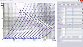
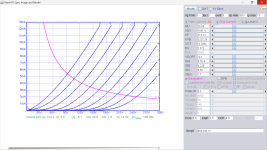
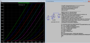
Here is ECB33 model, capacitance probably needs adjustment:
Code:
**** EBC33 ** Advanced Grid Current **********************************
* Created on 03/09/2023 11:17 using paint_kit.jar 3.1
* www.dmitrynizh.com/tubeparams_image.htm
* Plate Curves image file: ebc33.png
* Data source link:
*----------------------------------------------------------------------------------
.SUBCKT EBC33 1 2 3 ; Plate Grid Cathode
+ PARAMS: CCG=3P  CGP=1.4P CCP=1.9P
+ MU=31.49 KG1=2152.8 KP=269.84 KVB=2026.95 VCT=0.6852 EX=1.437
+ VGOFF=-0.6 IGA=0.001 IGB=0.3 IGC=8 IGEX=2.02
* Vp_MAX=500 Ip_MAX=17.5 Vg_step=1 Vg_start=0 Vg_count=14
* Rp=4000 Vg_ac=55 P_max=2 Vg_qui=-48 Vp_qui=300
* X_MIN=53 Y_MIN=21 X_SIZE=791 Y_SIZE=552 FSZ_X=1296 FSZ_Y=736 XYGrid=false
* showLoadLine=n showIp=y isDHT=n isPP=n isAsymPP=n showDissipLimit=y
* showIg1=y gridLevel2=y isInputSnapped=n
* XYProjections=n harmonicPlot=n dissipPlot=n
*----------------------------------------------------------------------------------
E1 7 0 VALUE={V(1,3)/KP*LOG(1+EXP(KP*(1/MU+(VCT+V(2,3))/SQRT(KVB+V(1,3)*V(1,3)))))}
RE1 7 0 1G  ; TO AVOID FLOATING NODES
G1 1 3 VALUE={(PWR(V(7),EX)+PWRS(V(7),EX))/KG1}
RCP 1 3 1G   ; TO AVOID FLOATING NODES
C1 2 3 {CCG} ; CATHODE-GRID
C2 2 1 {CGP} ; GRID=PLATE
C3 1 3 {CCP} ; CATHODE-PLATE
RE2 2 0 1G
EGC 8 0 VALUE={V(2,3)-VGOFF} ; POSITIVE GRID THRESHOLD
GG 2 3 VALUE={(IGA+IGB/(IGC+V(1,3)))*(MU/KG1)*(PWR(V(8),IGEX)+PWRS(V(8),IGEX))}
.ENDS
*$
Attachments
Last edited:
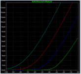
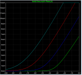
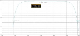
You may wish to watch this video to understand more about IV and transfer curve:
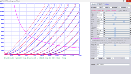
Transfer curve and IV curve are different ways in the display of the same tube so these curves are unique pairs so I think one can do reverse engineering from transfer back to IV. One needs to master in Paint Tool skill to regenerate IV curve, and as this is my first attempt any error please comment.
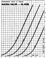
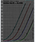
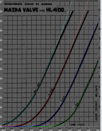
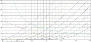
I use KC1 as reference but the transfer curve Ia is 3 times less than HL41DD, you need to set max Ia to 13ma.
I use KC1 as reference but the transfer curve Ia is 3 times less than HL41DD, you need to set max Ia to 13ma.
Code:
**** HL41DD ** Advanced Grid Current *****************16*****************
* Created on 03/10/2023 23:09 using paint_kit.jar 3.1
* www.dmitrynizh.com/tubeparams_image.htm
* Plate Curves image file:
* Data source link:
*----------------------------------------------------------------------------------
.SUBCKT HL41DD 1 2 3 ; Plate Grid Cathode
+ PARAMS: CCG=3.5P  CGP=3.5P CCP=4.5P
+ MU=28.04 KG1=1841.4 KP=213.12 KVB=3227.28 VCT=-0.2884 EX=1.372
+ VGOFF=-0.6 IGA=8.7E-4 IGB=0.228 IGC=6.56 IGEX=1.7
* Vp_MAX=300 Ip_MAX=13 Vg_step=1 Vg_start=0 Vg_count=9
* Rp=4000 Vg_ac=55 P_max=0.5 Vg_qui=-48 Vp_qui=300
* X_MIN=53 Y_MIN=51 X_SIZE=638 Y_SIZE=424 FSZ_X=1296 FSZ_Y=736 XYGrid=true
* showLoadLine=n showIp=y isDHT=n isPP=n isAsymPP=n showDissipLimit=y
* showIg1=y gridLevel2=y isInputSnapped=n
* XYProjections=n harmonicPlot=n dissipPlot=n
*----------------------------------------------------------------------------------
E1 7 0 VALUE={V(1,3)/KP*LOG(1+EXP(KP*(1/MU+(VCT+V(2,3))/SQRT(KVB+V(1,3)*V(1,3)))))}
RE1 7 0 1G  ; TO AVOID FLOATING NODES
G1 1 3 VALUE={(PWR(V(7),EX)+PWRS(V(7),EX))/KG1}
RCP 1 3 1G   ; TO AVOID FLOATING NODES
C1 2 3 {CCG} ; CATHODE-GRID
C2 2 1 {CGP} ; GRID=PLATE
C3 1 3 {CCP} ; CATHODE-PLATE
RE2 2 0 1G
EGC 8 0 VALUE={V(2,3)-VGOFF} ; POSITIVE GRID THRESHOLD
GG 2 3 VALUE={(IGA+IGB/(IGC+V(1,3)))*(MU/KG1)*(PWR(V(8),IGEX)+PWRS(V(8),IGEX))}
.ENDS
*$
Attachments
Last edited:
Thank you.
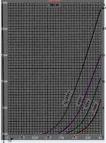
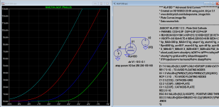
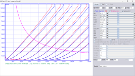
I make some refinement using the previous model as reference, try also:
I make some refinement using the previous model as reference, try also:
Code:
**** HL41DD ** Advanced Grid Current **********************************
* Created on 03/11/2023 14:34 using paint_kit.jar 3.1
* www.dmitrynizh.com/tubeparams_image.htm
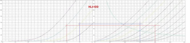
* Plate Curves image file: HL41DD.png
* Data source link:
*----------------------------------------------------------------------------------
.SUBCKT HL41DD 1 2 3 ; Plate Grid Cathode
+ PARAMS: CCG=3.5P CGP=3.5P CCP=4.5P
+ MU=30.58 KG1=1358.95 KP=221.05 KVB=1807.28 VCT=0.06 EX=1.277
+ VGOFF=-0.6 IGA=8.7E-4 IGB=0.228 IGC=6.56 IGEX=1.7
* Vp_MAX=300 Ip_MAX=13 Vg_step=1 Vg_start=0 Vg_count=9
* Rp=4000 Vg_ac=55 P_max=0.5 Vg_qui=-48 Vp_qui=300
* X_MIN=42 Y_MIN=15 X_SIZE=735 Y_SIZE=494 FSZ_X=1296 FSZ_Y=736 XYGrid=true
* showLoadLine=n showIp=y isDHT=n isPP=n isAsymPP=n showDissipLimit=y
* showIg1=y gridLevel2=y isInputSnapped=n
* XYProjections=n harmonicPlot=n dissipPlot=n
*----------------------------------------------------------------------------------
E1 7 0 VALUE={V(1,3)/KP*LOG(1+EXP(KP*(1/MU+(VCT+V(2,3))/SQRT(KVB+V(1,3)*V(1,3)))))}
RE1 7 0 1G ; TO AVOID FLOATING NODES
G1 1 3 VALUE={(PWR(V(7),EX)+PWRS(V(7),EX))/KG1}
RCP 1 3 1G ; TO AVOID FLOATING NODES
C1 2 3 {CCG} ; CATHODE-GRID
C2 2 1 {CGP} ; GRID=PLATE
C3 1 3 {CCP} ; CATHODE-PLATE
RE2 2 0 1G
EGC 8 0 VALUE={V(2,3)-VGOFF} ; POSITIVE GRID THRESHOLD
GG 2 3 VALUE={(IGA+IGB/(IGC+V(1,3)))*(MU/KG1)*(PWR(V(8),IGEX)+PWRS(V(8),IGEX))}
.ENDS
*$Attachments
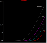
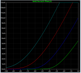
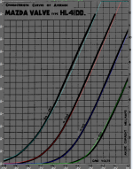
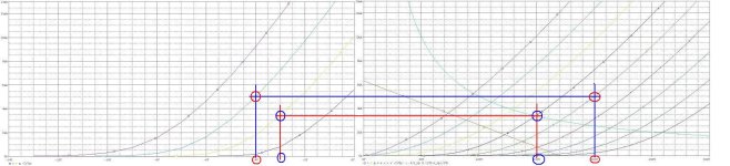
Here is the final version, again using previous version as refence to correct some misaligned areas:
Code:
**** HL41DD ** Advanced Grid Current **********************************
* Created on 03/11/2023 18:29 using paint_kit.jar 3.1
* www.dmitrynizh.com/tubeparams_image.htm
* Plate Curves image file: HL41DD.png
* Data source link:
*----------------------------------------------------------------------------------
.SUBCKT HL41DD 1 2 3 ; Plate Grid Cathode
+ PARAMS: CCG=3.5P  CGP=3.5P CCP=4.5P
+ MU=31.79 KG1=1143.51 KP=215.18 KVB=1807.28 VCT=0.1325 EX=1.133
+ VGOFF=-0.6 IGA=8.7E-4 IGB=0.228 IGC=6.56 IGEX=1.7
* Vp_MAX=300 Ip_MAX=13 Vg_step=1 Vg_start=0 Vg_count=9
* Rp=4000 Vg_ac=55 P_max=0.5 Vg_qui=-48 Vp_qui=300
* X_MIN=49 Y_MIN=15 X_SIZE=795 Y_SIZE=533 FSZ_X=1296 FSZ_Y=736 XYGrid=false
* showLoadLine=n showIp=y isDHT=n isPP=n isAsymPP=n showDissipLimit=n
* showIg1=y gridLevel2=y isInputSnapped=n
* XYProjections=n harmonicPlot=n dissipPlot=n
*----------------------------------------------------------------------------------
E1 7 0 VALUE={V(1,3)/KP*LOG(1+EXP(KP*(1/MU+(VCT+V(2,3))/SQRT(KVB+V(1,3)*V(1,3)))))}
RE1 7 0 1G  ; TO AVOID FLOATING NODES
G1 1 3 VALUE={(PWR(V(7),EX)+PWRS(V(7),EX))/KG1}
RCP 1 3 1G   ; TO AVOID FLOATING NODES
C1 2 3 {CCG} ; CATHODE-GRID
C2 2 1 {CGP} ; GRID=PLATE
C3 1 3 {CCP} ; CATHODE-PLATE
RE2 2 0 1G
EGC 8 0 VALUE={V(2,3)-VGOFF} ; POSITIVE GRID THRESHOLD
GG 2 3 VALUE={(IGA+IGB/(IGC+V(1,3)))*(MU/KG1)*(PWR(V(8),IGEX)+PWRS(V(8),IGEX))}
.ENDS
*$
Attachments
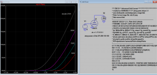
Hit me I might be being too literal and LTSpice doesn't "see" any differences in diode specifications, since does not allow them to be installed under components.
I modeled this: http://www.r-type.org/addtext/add158.htm (sans transformer since seems redundant and no pots since not an option in LTSpice), surprisingly got no errors and getting voltage, however, I don't know how to write and/or set up input voltage so getting way too low of a voltage out of HT (a few volts when probed).
Does anyone know how to set up an input for a power supply?
If not, fine, I now see my new assumption about diodes is correct, to LTSpice all the same. Plus, succeeded in creating a model 95 percent from scratch (copied the scripts @jcalvarez provided in another model). Though be nice to get it working, like to probe around and gain more understanding of circuits.
Thanks in advance!
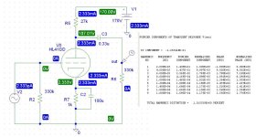
Spent about 45 minutes putting this in (copy and pasting into the script box turns it into one line of text) and it is not working. Of course, just my luck, ha. Is there an updated version, hopefully shorter? Did search, though found barely any material on this valve.Try this 6JC6-A GE model:
Code:**** 6JC6_A ****************************************** * Created on 07/12/2022 15:45 using paint_kip.jar * www.dmitrynizh.com/tubeparams_image.htm * Plate Curves image file: 6jc6-a.png * Data source link: <plate curves URL> *---------------------------------------------------------------------------------- .SUBCKT 6JC6_A P G2 G K ; LTSpice tetrode.asy pinout * .SUBCKT 6JC6_A P G K G2 ; Koren Pentode Pspice pinout + PARAMS: MU=57.08 KG1=212.97 KP=404.37 KVB=86.36 VCT=-0.2559 EX=1.092 KG2=203.74 KNEE=3502.28 KVC=1.863 + KLAM=2.504E-11 KLAMG=1.709E-4 KD=115.04 KC=1.191E-4 KR1=3.83E-5 KR2=0.0199 KVBG=4.18E-4 KB1=5.114 KB2=1.333 KB3=1.075 KB4=0.2418 KVBGI=1.645E-4 KNK=0.132 KNG=2.17E-5 KNPL=0.02082 KNSL=4.121E-4 KNPR=0.2031 KNSR=85.51 + CCG=8.5P CGP=0.019P CCP=3P VGOFF=-0.6 IGA=0.00106 IGB=0.12 IGC=9.84 IGEX=1.74 * Vp_MAX=500 Ip_MAX=35 Vg_step=1 Vg_start=0 Vg_count=12 * X_MIN=56 Y_MIN=36 X_SIZE=774 Y_SIZE=538 FSZ_X=1296 FSZ_Y=736 XYGrid=false * Rp=1400 Vg_ac=20 P_max=3.1 Vg_qui=-5.5 Vp_qui=300 * showLoadLine=n showIp=y isDHP=n isPP=n isAsymPP=n isUL=n showDissipLimit=y * showIg1=y isInputSnapped=y addLocalNFB=n * XYProjections=n harmonicPlot=y dissipPlot=n * UL=0.43 EG2=125 gridLevel2=y addKink=y isTanhKnee=n advSigmoid=y *---------------------------------------------------------------------------------- RE1 7 0 1G ; DUMMY SO NODE 7 HAS 2 CONNECTIONS E1 7 0 VALUE= ; E1 BREAKS UP LONG EQUATION FOR G1. +{V(G2,K)/KP*LOG(1+EXP((1/MU+(VCT+V(G,K))/SQRT(KVB+V(G2,K)*V(G2,K)))*KP))} RE2 6 0 1G ; DUMMY SO NODE 6 HAS 2 CONNECTIONS E2 6 0 VALUE={(PWR(V(7),EX)+PWRS(V(7),EX))} ; Kg1 times KIT current E4 8 0 VALUE={V(P,K)/KNEE/(KVBGI+V(6)*KVBG)} E5 81 0 VALUE={PWR(V(8),KB1)} E6 82 0 VALUE={PWR(V(8),KB2)} E7 83 0 VALUE={PWR(V(8),KB3)} E8 9 0 VALUE={PWR(1-EXP(-V(81)*(KC+KR1*V(82))/(KD+KR2*V(83))),KB4)*1.5708} RE4 8 0 1 RE5 81 0 1 RE6 82 0 1 RE7 83 0 1 RE8 9 0 1 RE21 21 0 1 E21 21 0 VALUE={V(6)/KG1*V(9)} ; Ip with knee but no slope and no kink RE22 22 0 1 ; E22: kink curr deviation for plate E22 22 0 VALUE={V(21)*LIMIT(KNK-V(G,K)*KNG,0,0.3)*(-ATAN((V(P,K)-KNPL)/KNSL)+ATAN((V(P,K)-KNPR)/KNSR))} G1 P K VALUE={V(21)*(1+KLAMG*V(P,K))+KLAM*V(P,K) + V(22)} G2 G2 K VALUE={V(6)/KG2*(KVC-V(9))/(1+KLAMG*V(P,K)) - V(22)} RCP P K 1G ; FOR CONVERGENCE C1 K G {CCG} ; CATHODE-GRID 1 C2 G P {CGP} ; GRID 1-PLATE C3 K P {CCP} ; CATHODE-PLATE RE23 G 0 1G GG G K VALUE={(IGA+IGB/(IGC+V(P,K)))*(MU/KG1)* +(PWR(V(G,K)-VGOFF,IGEX)+PWRS(V(G,K)-VGOFF,IGEX))} .ENDS *$
Or did I mistype something?
This is a very rough draft, need to do a run to see if even works (know the paralleled SL7s work, ran that first, then didn't bother running the JC6 without the 26), then make adjustments.
Thanks in advance for any help!
Edit. Forgot the OPT, it ish here: https://www.diyaudio.com/community/threads/ltspice-hierarchical-ultralinear-opt.379431/#post-6882330.
Attachments
Last edited:
Maybe it's just me, but it seems like this thread has devolved into a general dialog about SPICE modeling, and about a specific project. Perhaps this conversation needs to be moved to the "Software Tools" section where LTspice simulation issues are discussed. Then this thread can get back to being about vacuum tube SPICE models?
Oops, good point.Maybe it's just me, but it seems like this thread has devolved into a general dialog about SPICE modeling, and about a specific project. Perhaps this conversation needs to be moved to the "Software Tools" section where LTspice simulation issues are discussed. Then this thread can get back to being about vacuum tube SPICE models?
What about discussing valve models? Can we sort out a script for a 6JC6 or 12JC6, please?
I would delete my post, however, too much time has elapsed.
it seems like this thread has devolved into a general dialog about SPICE modeling, and about a specific project. Perhaps this conversation needs to be moved to the "Software Tools" section
 The conversation can be moved. Please let us know what posts - or range of posts - should be moved.
Actually... Yes. I collected a couple a while ago.
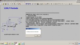
Code:**************************************************** .SUBCKT GE_12HL7_125 1 2 3 4 ; A G2 G1 C; [LIST] [*]Extract V1.998 [*]Model created: 13-Jun-2016 [*]NOTE: LOG(x) is base e LOG or natural logarithm. [*]For some Spice versions, e.g. MicroCap, this has to be changed to LN(x). [/LIST] X1 1 2 3 4 BTetrodeDE MU= 30.35 EX=1.585 kG1= 97.9 KP= 297.3 kVB = .0 kG2= 434.9 +Sc=.23E-01 ap= .014 w= 18. nu= 15.50 lam= 11715.6 [LIST] [*]Ookg1mOokG2=.792E-02 Aokg1=.56E-05 alkg1palskg2=.792E-02 be= .084 als= 2.84 RGI=2000 [*]CCG1=0.0P CCG2 = 0.0p CPG1 = 0.0p CG1G2 = 0.0p CCP=0.0P ; [/LIST] .ENDS [/QUOTE] This model does not work, returns an error. Anyone happen to know how to resolve these other than deleting and mind sharing, please? [ATTACH type="full"]1153758[/ATTACH] Circuit credit goes to José ([USER=518328]@jcalvarez[/USER] ).
Attachments
By golly that worked, thank you!
- Home
- Amplifiers
- Tubes / Valves
- Vacuum Tube SPICE Models