Thank you for the .asy file!Here are models for most of the common 1N400x diodes.
")
Also, let me try attaching the .asc file again.
Edit. The .asy file provided is doing the same darn thing as before, not showing up after being selected. So this needs to be resolved so can put in the provided .asy file.
Attachments
Last edited:
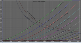
Triode connected 1619 is found here: https://www.audio-talk.co.uk/phpBB3...id=59ab91dc66108c9490a7d6a73a43489f&mode=view
You can plot the triode curve using pentode model just like the actual tube by connecting screen to plate. I usually don't make a separate triode model.
Try this 1619 RCA model:
You can plot the triode curve using pentode model just like the actual tube by connecting screen to plate. I usually don't make a separate triode model.
Try this 1619 RCA model:
Code:
**** 1619 ******************************************
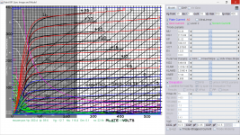
* Created on 03/04/2023 00:29 using paint_kip.jar
* www.dmitrynizh.com/tubeparams_image.htm
* Plate Curves image file: 1619.png
* Data source link: <plate curves URL>
*----------------------------------------------------------------------------------
.SUBCKT 1619 P G2 G K ; LTSpice tetrode.asy pinout
* .SUBCKT 1619 P G K G2 ; Koren Pentode Pspice pinout
+ PARAMS: MU=10.26 KG1=2173.88 KP=81.52 KVB=1082.67 VCT=0.07085 EX=1.323 KG2=5368.58 KNEE=17.84 KVC=1.608
+ KLAM=3.125E-10 KLAMG=2.354E-4 KD=974.18 KC=0.03139 KR1=7.076E-4 KR2=4.859 KVBG=1.579E-7 KB1=1.293 KB2=1.86 KB3=2 KB4=2.338 KVBGI=5.841E-4 KNK=-0.004269 KNG=0.008371 KNPL=0.6438 KNSL=1.078 KNPR=250.91 KNSR=138.08
+ CCG=10.5P CGP=0.35P CCP=12.5P VGOFF=-0.987 IGA=0.006229 IGB=0.2259 IGC=0.41 IGEX=1.872
* Vp_MAX=550 Ip_MAX=400 Vg_step=5 Vg_start=35 Vg_count=18
* X_MIN=67 Y_MIN=17 X_SIZE=789 Y_SIZE=570 FSZ_X=1296 FSZ_Y=736 XYGrid=false
* Rp=1400 Vg_ac=20 P_max=15 Vg_qui=-7.5 Vp_qui=300
* showLoadLine=n showIp=y isDHP=n isPP=n isAsymPP=n isUL=n showDissipLimit=y
* showIg1=y isInputSnapped=y addLocalNFB=n
* XYProjections=n harmonicPlot=y dissipPlot=n
* UL=0.43 EG2=300 gridLevel2=y addKink=y isTanhKnee=n advSigmoid=y
*----------------------------------------------------------------------------------
RE1 7 0 1G ; DUMMY SO NODE 7 HAS 2 CONNECTIONS
E1 7 0 VALUE= ; E1 BREAKS UP LONG EQUATION FOR G1.
+{V(G2,K)/KP*LOG(1+EXP((1/MU+(VCT+V(G,K))/SQRT(KVB+V(G2,K)*V(G2,K)))*KP))}
RE2 6 0 1G ; DUMMY SO NODE 6 HAS 2 CONNECTIONS
E2 6 0 VALUE={(PWR(V(7),EX)+PWRS(V(7),EX))} ; Kg1 times KIT current
E4 8 0 VALUE={V(P,K)/KNEE/(KVBGI+V(6)*KVBG)}
E5 81 0 VALUE={PWR(V(8),KB1)}
E6 82 0 VALUE={PWR(V(8),KB2)}
E7 83 0 VALUE={PWR(V(8),KB3)}
E8 9 0 VALUE={PWR(1-EXP(-V(81)*(KC+KR1*V(82))/(KD+KR2*V(83))),KB4)*1.5708}
RE4 8 0 1
RE5 81 0 1
RE6 82 0 1
RE7 83 0 1
RE8 9 0 1
RE21 21 0 1
E21 21 0 VALUE={V(6)/KG1*V(9)} ; Ip with knee but no slope and no kink
RE22 22 0 1 ; E22: kink curr deviation for plate
E22 22 0 VALUE={V(21)*LIMIT(KNK-V(G,K)*KNG,0,0.3)*(-ATAN((V(P,K)-KNPL)/KNSL)+ATAN((V(P,K)-KNPR)/KNSR))}
G1 P K VALUE={V(21)*(1+KLAMG*V(P,K))+KLAM*V(P,K) + V(22)}
G2 G2 K VALUE={V(6)/KG2*(KVC-V(9))/(1+KLAMG*V(P,K)) - V(22)}
RCP P K 1G ; FOR CONVERGENCE
C1 K G {CCG} ; CATHODE-GRID 1
C2 G P {CGP} ; GRID 1-PLATE
C3 K P {CCP} ; CATHODE-PLATE
RE23 G 0 1G
GG G K VALUE={(IGA+IGB/(IGC+V(P,K)))*(MU/KG1)*
+(PWR(V(G,K)-VGOFF,IGEX)+PWRS(V(G,K)-VGOFF,IGEX))}
.ENDS
*$Attachments
Last edited:
Files begin with "._" do not belong to Windows, it belongs to Mac OSX which should be hidden. If those LTSpice files are originated from there and then copy to Windows it will show up.
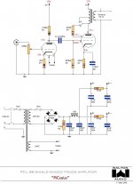
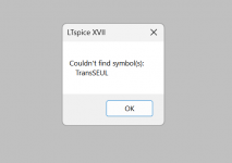
Regarding your Walton PCL86 SE/UL amp simulation, check the correctness of your schematic wiring (see attached). Can you also attached OPT "TransSeUl" symbol and related .inc model files?
Regarding your Walton PCL86 SE/UL amp simulation, check the correctness of your schematic wiring (see attached). Can you also attached OPT "TransSeUl" symbol and related .inc model files?
Attachments
Last edited:
Not all of the missing files are of this ilk, for example, the 1N4007 (I have looked so many times accidentally memorized the number).Files begin with "._" do not belong to Windows, it belongs to Mac OSX which should be hidden
Too bad not a way to put in diodes other than what is provided, with no similarities, sure limits schematics to be evaluated. Oh well, now I know.
How does this schematic, which looks exactly the same, differ? I am not seeing any...Regarding your Walton PCL86 SE/UL amp simulation, check the correctness of your schematic wiring (see attached).
I did not receive .inc files, do have the others. For .inc files there is a spreadsheet that can generate those now think about it. Attached the .asy files, both in case one is better then the other.Can you also attached OPT "TransSeUl" symbol and related .inc model files?
I installed a SEUL that was provided to me, which was from a reliable source. Where I stuggled was translating the schematic OPT, which looks nothing like the block, to the SEUL. Look at the schematic, there is no signal or "p" terminals. I assumed "p" is the UL tap and connected it to the plate.
Attachments
Last edited:
You should attach all the related files, not just the .asc. if you don't want then that is ok, the help also end there.
From you post https://www.diyaudio.com/community/threads/vacuum-tube-spice-models.243950/post-7286904
the P and and Sg are short circuited, that is why I asked you to check. And R4 connection is wrong. The actual schematic is misleading too. R4 is supposed to connect to the mid point of the switch not directly to plate!
Attachments
Last edited:
Weird they didn't attach, let me try again, please.You should attached all the related files, not just the .asc. if you don't want then that is ok, the help also end there.
Will provide one at a time, maybe the file size is too large.
Attachments
I was trying to eliminate the switch as there are none in the files for high voltages without Vss, what ever that is. Now with R4 in the right place, think might have it. Left my cellular in my friend's vehicle, see him tomorrow and no one calls me, so get it then, so try a PDF.[...]the P and and Sg are short circuited[...]
Interesting, I appreciate letting me know, thank you!And R4 connection is wrong. The actual schematic is misleading too. R4 is supposed to connect to the mid point of the switch not directly to plate!
Attachments
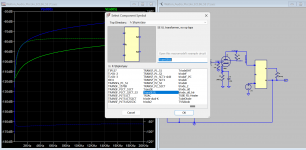
If you're going to use Ham1628SE model then it must be added to your TransSEUL symbol:
I have done that for you now run without errors, you can check further. The speaker out can not be shorted (as in your sch.)
Code:
Version 4
SymbolType BLOCK
RECTANGLE Normal 103 232 -24 -71
SYMATTR Prefix X
SYMATTR Description SE UL transformer, no op taps
SYMATTR SpiceModel Ham1628SE
SYMATTR ModelFile Ham1628SE.txt
PIN -32 -16 LEFT 8
PINATTR PinName P
PINATTR SpiceOrder 1
PIN -32 80 LEFT 8
PINATTR PinName Sg
PINATTR SpiceOrder 2
PIN -32 176 LEFT 8
PINATTR PinName B
PINATTR SpiceOrder 3
PIN 112 16 RIGHT 8
PINATTR PinName Sp1
PINATTR SpiceOrder 4
PIN 112 144 RIGHT 8
PINATTR PinName Sp2
PINATTR SpiceOrder 5
I have done that for you now run without errors, you can check further. The speaker out can not be shorted (as in your sch.)
Attachments
Where do I put this code? In the script of the model?If you're going to use Ham1628SE model then it must be added to your TransSEUL symbol:
I hate to say, still getting the same darn error code. Turns out in the file transfer it stripped the code, not visible in the model.I have done that for you now run without errors, you can check further. The speaker out can not be shorted (as in your sch.)
Seems yet another SE that can't be modeled (other one was because 1N4007 diodes are not available in LTSpice). I am beginning to dislike SEs because they can't be easily modeled like PPs.
Last edited:
You save the code in asy subdirectory as TransSEUL.txt or TransSEUL.asy or any other name. Then it should appear under asy sub-directory or any subdir where LTSpice has a path to it. In addition to default search path you can add other paths.
Attachments
I don't know what this means.You save the code in asy subdirectory as TransSEUL.txt or TransSEUL.asy or any other name.
I copied the file path from the "save as" for the SE PU and pasted it exactly like the darn picture and the damn error is still present! What the heck?!In addition to default search path you can add other paths.
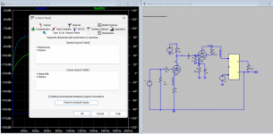
Not only is there this persistent and false error code, also getting:
Node NC_02 is floating.
Less than two connections to node nc_01. This node is used by v3.
'' to node nc_02. This node is used by v3.
I am beginning to suspect there is a bug in the program and need to wipe it off the hard drive and re-install, since all the attempts to fix have provided no resolution. Or am I missing something?
Thank you!Your attached Walton SE sch asc appear to be incorrectly simulated even though the schematic drawn is morel or less accurate. I am now investigating and redrawn to see the differences and where the errors come in.
- Home
- Amplifiers
- Tubes / Valves
- Vacuum Tube SPICE Models