Hi RongonHi Rongon
My i4 sometimes shows convergence issues, which is largely improved since i5 or newer.
I will provide an updated 6N6P model the next days.
BR Adrian
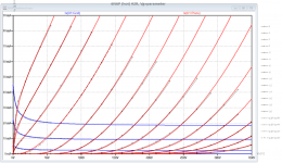
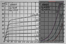
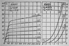
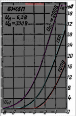
It took some days due to heavily limited free time, but now I coped to create a new version of the 6N6P. I repeated also the measurements, this time with hot plate, as I have learned that triodes sometimes show different curves when hot.
But the 6N6P seems to be a very good construction - there was almost no difference between hot and cold tube.
BR Adrian
Code:
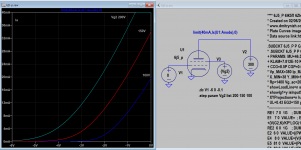
*6N6P LTspice model based on the generic triode model from Adrian Immler, version i6
*A version log is at the end of this file
*100h BurnIn of 4 Novosibirsk factory tubes, sample selection and measurements done in Febr 2021
*Params fitted to the measured values by Adrian Immler, Jan 2023
*This model is accurate for Vg up to 6V.
*The high fit quality is presented at adrianimmler.simplesite.com
*History's best of tube describing art (plus some new ideas) is merged to this new approach.
*@ neg. Vg, Ia accuracy is similar to Koren models, and unrivaled for remote cutoff triodes
*@ small neg. Vg, the "Anlauf" current is considered.
*@ pos. Vg, Ig and Ia accuracy is on an unrivaled level (including neg. Va range!)
*This offers new simulation possibilities like grid resistor bias, backward plate modulated stages,
*Audion radio circuits, low voltage amps, guitar distortion stages or pulsed stages.
*
*            i6 version is identical to the i5, but measurements done with HOT anode for highest accuracy
*            |  anode (plate)
*            |  | grid
*            |  | | cathode
*            |  | | |
.subckt 6N6P.i6 A G K
+ params:
*Parameters for space charge current Is (100% assigned to Ia @ Vg < 0)
+ mu   = 20.3  ;Determines the voltage gain @ constant Ia
+ rad  = 1k1   ;Differential anode resistance, set @ Iad and Vg=0V
+ Vct  = -0.85 ;Offsets the Ia-traces on the Va axis. Electrode material's contact potential
+ kp   = 91    ;Mimics the island effect
+ xs   = 1.60  ;Determines the curve of the Ia traces. Typically between 1.2 and 1.8
+ kIsr = 15m   ;Va-indepedent part of the Is reduction when gridcurrent occurs
+ kvdg  = 75   ;Va-depedent part of the Is reduction when gridcurrent occurs
*
*Parameters for assigning the space charge current to Ia and Ig @ Vg > 0
+ kB   = 0.35  ;Describes how fast Ia drops to zero when Va approaches zero.
+ radl = 10    ;Differential resistance for the Ia emission limit @ very small Va and Vg > 0
+ tsh  = 5     ;Ia transmission sharpness from 1th to 2nd Ia area. Keep between 3 and 20. Start with 20.
+ xl   = 1.2   ;Exponent for the emission limit
*
*Parameters of the grid-cathode vacuum diode
+ kg = 675     ;Inverse scaling factor for the Va independent part of Ig (caution - interacts with xg!)
+ Vctg = -0.7  ;Offsets the log Ig-traces on the Vg axis. Electrode material's contact potential
+ xg   = 1.5   ;Determines the curve of the Ig slope versus (positive) Vg and Va >> 0
+ VT   = 0.107 ;Log(Ig) slope @ Vg<0. VT=k/q*Tk (cathodes absolute temp, typically 1150K)
+ rTr  = 0.9   ;ratio of VT for Igr. Typically 0.8
+ kVT  = 30m   ;Va dependant koeff. of VT
+ gft1 = 0     ;reduces the steering voltage around Vg=-Vg0, for finetuning purposes
+ gft1a= 0.9   ;reduces the steering voltage around Vg=-Vg0. Effect decreases with 1/(1+kB*Va)
+ gft2 = 0.3   ;finetunes the Igr drop @ incrasing Va and around Vg=-Vg0
*
*Parameters for the caps
+ cag  = 3p5   ;From datasheet
+ cak  = 1p85  ;From datasheet
+ cgk  = 4p4   ;From datasheet
*
*special purpose parameters
+ os = 1       ;Overall scaling factor, if a user wishes to simulate manufacturing tolerances
+ murc = 10    ;Mu of the remote cutoff triode
+ ksrc = 10G   ;Inverse Iarc gain factor for the remote cuttoff triode
+ kprc = 1k    ;Mimics the island effect for the remote cotoff triode
+ Vbatt = 0    ;heater battery voltage for direct heated battery triodes
+ Vdrmax = 100 ;max voltage of internal Vg drop, for convergence improvements
*
*Calculated parameters
+ Iad = {100/rad} ;Ia where the anode a.c. resistance is set according to rad.
+ ks = {pow(mu/(rad*xs*Iad**(1-1/xs)),-xs)} ;Reduces the unwished xs influence to the Ia slope
+ ksnom = {pow(mu/(rad*1.5*Iad**(1-1/1.5)),-1.5)} ;Sub-equation for calculating Vg0
+ Vg0 = {Vct + (Iad*ks)**(1/xs) - (Iad*ksnom)**(2/3)} ;Reduces the xs influence to Vct.
+ kl = {pow(1/(radl*xl*Ild**(1-1/xl)),-xl)} ;Reduces the xl influence to the Ia slope @ small Va
+ Ild = {sqrt(radl)*1m} ;Current where the Il a.c. resistance is set according to radl.
*
*Space charge current model
Rak A K 100G ;avoids "floating net" errors
Bft   ft 0 V=1/(1+pow(2*abs(v(G,Ki)+Vg0),3)) ;an auxiliary voltage to finetune the triode around Vg=-Vg0
Bggi GGi 0 V=(v(Gi,Ki)+Vg0)*(1/(1+kIsr*max(0, v(G,Ki)+Vg0))) - gft1*v(ft) - gft1a*v(ft)/(1+kB*v(Ahc)) ;Effective internal grid voltage.
Bahc Ahc 0 V=uramp(v(A,Ki)) ;Anode voltage, hard cut to zero @ neg. value
Bst   St 0 V=uramp(max(v(GGi)+v(A,Ki)/(mu), v(A,Ki)/kp*ln(1+exp(kp*(1/mu+v(GGi)/(1+v(Ahc)))))));Steering volt.
Bs    Ai Ki I=os/ks*pow(v(St),xs) ;Langmuir-Childs law for the space charge current Is
*Bstrc Strc 0 V=uramp(max(v(GGi)+v(Ahc)/(murc), v(Ahc)/kprc*ln(1+exp(kprc*(1/murc+v(GGi)/(1+v(Ahc)))))));FOR REMOTE CUTOFF TUBES ONLY
*Bsrc   Ai Ki I=os/ksrc*pow(v(Strc),xs) ;FOR REMOTE CUTOFF TUBES ONLY
*
*Anode current limit @ small Va
.func smin(z,y,k) {pow(pow(z+1f, -k)+pow(y+1f, -k), -1/k)} ;Min-function with smooth trans.
.func ssmin(z,y,k) {min(min(z,y), smin(z*1.003,y*1.003,k))};smin-function which suppresses small residual differencies
Ra  A Ai 1
Bgl Gi A I=uramp(i(Ra)-ssmin(1/kl*pow(v(Ahc),xl),i(Ra),tsh)) ;Ia emission limit
*
*Grid model
Rgk G K 10G ;avoids "floating net" errors
Bvdg G Gi I=1/kvdg*pow(v(G,Gi),1.5) ;Reduces the internal effective grid voltage when Ig rises
Bcoh G Gi I=pow(uramp(v(G,Gi)-Vdrmax),2) ;A convergence help which softly limits the internal Vg voltage drop.
Rgip G Gi 1G ;avoids some warnings
.func fVT() {VT*exp(-kVT*sqrt(v(A,Ki)))}
.func Ivd(Vvd, kvd, xvd, VTvd)  {if(Vvd < 3, 1/kvd*pow(VTvd*xvd*ln(1+exp(Vvd/VTvd/xvd)),xvd), 1/kvd*pow(Vvd, xvd))} ;Vacuum diode function
Bgvd G Ki I=Ivd(v(G,Ki) + Vctg + min(0,v(A,Ki)/mu), kg/os, xg, fVT()) ;limits the internal Vg for convergence reasons
Bstn Stn 0 V=v(GGi)+min(0,v(A,Ki))/mu ;special steering voltage, sensitive to negative Anodevoltages only
Bgr Gi Ai I= ivd(v(Stn),ks/os, xs, rTr*fVT())/(1+(kB+v(ft)*gft2)*v(Ahc));Is reflection to grid when Va approaches zero
*Bgr Gi Ai I=(ivd(v(Stn),ks/os, xs, rTr*fVT())+os/ksrc*pow(v(GGi),xs))/(1+(kB+v(ft)*gft2)*v(Ahc));FOR REMOTE CUTOFF TUBES ONLY
Bs0 Ai Ki  I=uramp(ivd(v(Stn),ks/os, xs, rTr*fVT()) - os/ks*pow(v(Stn),xs))
Bbatt Ki K V=Vbatt/2 ;for battery heated triodes; Offsets the average cathode potential to the half heater battery voltage
*
*Caps
C1 A G {cag}
C2 A K {cak}
C3 G K {cgk}
.ends
*
*Version log
*i1 :Initial version
*i2 :Pin order changed to the more common order A G K (Thanks to Markus Gyger for his tip)
*i3 :bugfix of the Ivd-function: now also usable for larger Vvd
*i4: Rgi replaced by a virtual vacuum diode (better convergence). ft1 deleted (no longer needed)
;2 new prarams for Ig finetuning @ Va and Vg near zero. New overall skaling factor os for aging etc.
*i5: improved convergence performance. PosVg/NegVa area now correct. Also accurate now for remote cutoff triodes!
*i6: identical to the i5, but tubes measured with hot anode (Pa=0.7*Pmax) for highest accuracy
Attachments
@Adrian Immler
I have been looking at your models with interest, I must admit your paper will take a lot of reading and the math is probably beyond me.
I have been using a pentode model in LtSpice which I think is a Koren style. I hit a problem with it: the G2 current is far higher than the anode current. This makes moulding a long-tailed pair impossible.
I would like to try your model but I could not find any description of how you calculate the parameters in the model from your traces. Do you have any advice on how to adapt one of your models to a different tube? I don't have anything like your iTrace but I have been manually plotting curves so knowing what to measure would also be useful.
Regards
AdrianR
Hi AdrianR
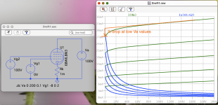
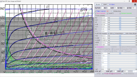
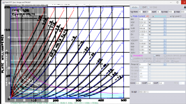
Thanks for your interest in my models. I set the parameters for my models not by calculation, but by trial and error. The fitting principle is the same as with Dmitry's famous Model Paint Tool:
https://www.dmitrynizh.com/tubeparams_image.htm
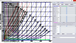
Due to my lack of a tool similar to Dmitry's (but with my model behind), I overlay the measured curves as a half-transparent picture over the curves generated in LTspice. As you can imagine, this workflow is as convenient as landing the Apollo Lunar Module on the moon! So, If you can live without g1 grid current, better try it with the Model Paint Tool.
BR Adrian
... BTW, Koonw is very experienced in using this tool, and is often asked in this thread for generating spice models - so, to ask him might be also an option.
Thanks for your interest in my models. I set the parameters for my models not by calculation, but by trial and error. The fitting principle is the same as with Dmitry's famous Model Paint Tool:
https://www.dmitrynizh.com/tubeparams_image.htm
Due to my lack of a tool similar to Dmitry's (but with my model behind), I overlay the measured curves as a half-transparent picture over the curves generated in LTspice. As you can imagine, this workflow is as convenient as landing the Apollo Lunar Module on the moon!
So, If you can live without g1 grid current, better try it with the Model Paint Tool.BR Adrian
... BTW, Koonw is very experienced in using this tool, and is often asked in this thread for generating spice models - so, to ask him might be also an option.
Hi @Adrian Immler
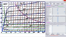
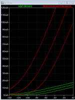
Thanks for the reply, I have just been trying your 6BW6 in LtSpice, it looks very close to these specs http://www.r-type.org/pdfs/6bw6.pdf
I have noticed the screen grid current is different when Va < 15. I see a kink upward in the Screen current (green) and it crosses the axis at 95mA where the data sheet is at 60mA. Would this be due to what you call the "Va independable ig2 part"?
Thanks once again Adrian. I'll give it a try and let you know if I run into any issues.Hi Rongon
It took some days due to heavily limited free time, but now I coped to create a new version of the 6N6P. I repeated also the measurements, this time with hot plate, as I have learned that triodes sometimes show different curves when hot.
But the 6N6P seems to be a very good construction - there was almost no difference between hot and cold tube.
BR Adrian
Nice observation that the 6N6P measures very nearly the same heated up as when just powered on. I've been using this double triode for at least 10 years now, and it's always worked well in circuits. I think it's a good one.
Hi AdrianRHi @Adrian Immler
Thanks for the reply, I have just been trying your 6BW6 in LtSpice, it looks very close to these specs http://www.r-type.org/pdfs/6bw6.pdf
I have noticed the screen grid current is different when Va < 15. I see a kink upward in the Screen current (green) and it crosses the axis at 95mA where the data sheet is at 60mA. Would this be due to what you call the "Va independable ig2 part"
No, this is something different. For tetrodes/pentodes, the total amount of emitted current is somehow "constant" for a given g2 voltage, especially for signal pentodes. Derk Reefman used this law for his pentode models. However, some pentodes differ from that rule at very low Va values: The cathode current drops short before Va approaches zero. This Ik drop effect is also present in triodes.
My models, for triodes as well as for pentodes, are able to mimic this Ik drop effect up to a certain amount only. If the effect is too strong, and I would force the model to mimic that in full amount, the model would suffer under convergence issues. Something I want to avoid! That is why the 6BW6 model shows a deviation for Ig2 at very low Va values.
BR Adrian
Attachments
Try this model:
Code:
**** 6J5_P 6Ж5П 6Zh5P ******************************************
* Created on 02/06/2023 16:16 using paint_kip.jar
* www.dmitrynizh.com/tubeparams_image.htm
* Plate Curves image file: 6J5-P.png
* Data source link:https://voltradio.ru/6zh5p
*----------------------------------------------------------------------------------
.SUBCKT 6J5_P P G2 G K ; LTSpice tetrode.asy pinout
* .SUBCKT 6J5_P P G K G2 ; Koren Pentode Pspice pinout
+ PARAMS: MU=46.57 KG1=606.96 KP=267.79 KVB=1039.94 VCT=0.0987 EX=1.4 KG2=715.36 KNEE=1 KVC=2.179
+ KLAM=7.812E-10 KLAMG=7.546E-4  KD=51.39 KC=0.0035 KR1=0.1939 KR2=0.00992 KVBG=0.2112 KB1=0.1375 KB2=1.96 KB3=2 KB4=0.74 KVBGI=2.734E-7 KNK=-0.06776 KNG=0.006 KNPL=50 KNSL=11 KNPR=120 KNSR=29
+ CCG=8.5P CGP=0.03P CCP=2.2P VGOFF=-0.6 IGA=0.001 IGB=0.3 IGC=8 IGEX=2
* Vp_MAX=380 Ip_MAX=35 Vg_step=1 Vg_start=0 Vg_count=9
* X_MIN=38 Y_MIN=12 X_SIZE=835 Y_SIZE=578 FSZ_X=1296 FSZ_Y=736 XYGrid=true
* Rp=1400 Vg_ac=20 P_max=3.8 Vg_qui=-4 Vp_qui=300
* showLoadLine=n showIp=y isDHP=n isPP=n isAsymPP=n isUL=n showDissipLimit=y
* showIg1=y isInputSnapped=y addLocalNFB=n
* XYProjections=n harmonicPlot=y dissipPlot=n
* UL=0.43 EG2=150 gridLevel2=y addKink=y isTanhKnee=n advSigmoid=y
*----------------------------------------------------------------------------------
RE1  7 0  1G    ; DUMMY SO NODE 7 HAS 2 CONNECTIONS
E1   7 0  VALUE=  ; E1 BREAKS UP LONG EQUATION FOR G1.
+{V(G2,K)/KP*LOG(1+EXP((1/MU+(VCT+V(G,K))/SQRT(KVB+V(G2,K)*V(G2,K)))*KP))}
RE2  6 0  1G    ; DUMMY SO NODE 6 HAS 2 CONNECTIONS
E2  6 0  VALUE={(PWR(V(7),EX)+PWRS(V(7),EX))} ; Kg1 times KIT current
E4   8 0  VALUE={V(P,K)/KNEE/(KVBGI+V(6)*KVBG)}
E5  81 0  VALUE={PWR(V(8),KB1)}
E6  82 0  VALUE={PWR(V(8),KB2)}
E7  83 0  VALUE={PWR(V(8),KB3)}
E8   9 0  VALUE={PWR(1-EXP(-V(81)*(KC+KR1*V(82))/(KD+KR2*V(83))),KB4)*1.5708}
RE4  8 0  1
RE5 81 0  1
RE6 82 0  1
RE7 83 0  1
RE8  9 0  1
RE21 21 0 1
E21  21 0 VALUE={V(6)/KG1*V(9)} ; Ip with knee but no slope and no kink
RE22 22 0 1 ; E22: kink curr deviation for plate
E22  22 0 VALUE={V(21)*LIMIT(KNK-V(G,K)*KNG,0,0.3)*(-ATAN((V(P,K)-KNPL)/KNSL)+ATAN((V(P,K)-KNPR)/KNSR))}
G1   P K  VALUE={V(21)*(1+KLAMG*V(P,K))+KLAM*V(P,K) + V(22)}
G2   G2 K  VALUE={V(6)/KG2*(KVC-V(9))/(1+KLAMG*V(P,K)) - V(22)}
RCP  P K  1G     ; FOR CONVERGENCE
C1   K G  {CCG}  ; CATHODE-GRID 1
C2   G P  {CGP}  ; GRID 1-PLATE
C3   K P  {CCP}  ; CATHODE-PLATE
RE23 G 0 1G
GG G K VALUE={(IGA+IGB/(IGC+V(P,K)))*(MU/KG1)*
+(PWR(V(G,K)-VGOFF,IGEX)+PWRS(V(G,K)-VGOFF,IGEX))}
.ENDS
*$
Attachments
I'm having trouble using this model.Try this model:
Code:**** 6J5_P 6Ж5П 6Zh5P ****************************************** * Created on 02/06/2023 16:16 using paint_kip.jar * www.dmitrynizh.com/tubeparams_image.htm * Plate Curves image file: 6J5-P.png * Data source link:https://voltradio.ru/6zh5p *---------------------------------------------------------------------------------- .SUBCKT 6J5_P P G2 G K ; LTSpice tetrode.asy pinout * .SUBCKT 6J5_P P G K G2 ; Koren Pentode Pspice pinout + PARAMS: MU=46.57 KG1=606.96 KP=267.79 KVB=1039.94 VCT=0.0987 EX=1.4 KG2=715.36 KNEE=1 KVC=2.179 + KLAM=7.812E-10 KLAMG=7.546E-4 KD=51.39 KC=0.0035 KR1=0.1939 KR2=0.00992 KVBG=0.2112 KB1=0.1375 KB2=1.96 KB3=2 KB4=0.74 KVBGI=2.734E-7 KNK=-0.06776 KNG=0.006 KNPL=50 KNSL=11 KNPR=120 KNSR=29 + CCG=8.5P CGP=0.03P CCP=2.2P VGOFF=-0.6 IGA=0.001 IGB=0.3 IGC=8 IGEX=2 * Vp_MAX=380 Ip_MAX=35 Vg_step=1 Vg_start=0 Vg_count=9 * X_MIN=38 Y_MIN=12 X_SIZE=835 Y_SIZE=578 FSZ_X=1296 FSZ_Y=736 XYGrid=true * Rp=1400 Vg_ac=20 P_max=3.8 Vg_qui=-4 Vp_qui=300 * showLoadLine=n showIp=y isDHP=n isPP=n isAsymPP=n isUL=n showDissipLimit=y * showIg1=y isInputSnapped=y addLocalNFB=n * XYProjections=n harmonicPlot=y dissipPlot=n * UL=0.43 EG2=150 gridLevel2=y addKink=y isTanhKnee=n advSigmoid=y *---------------------------------------------------------------------------------- RE1 7 0 1G ; DUMMY SO NODE 7 HAS 2 CONNECTIONS E1 7 0 VALUE= ; E1 BREAKS UP LONG EQUATION FOR G1. +{V(G2,K)/KP*LOG(1+EXP((1/MU+(VCT+V(G,K))/SQRT(KVB+V(G2,K)*V(G2,K)))*KP))} RE2 6 0 1G ; DUMMY SO NODE 6 HAS 2 CONNECTIONS E2 6 0 VALUE={(PWR(V(7),EX)+PWRS(V(7),EX))} ; Kg1 times KIT current E4 8 0 VALUE={V(P,K)/KNEE/(KVBGI+V(6)*KVBG)} E5 81 0 VALUE={PWR(V(8),KB1)} E6 82 0 VALUE={PWR(V(8),KB2)} E7 83 0 VALUE={PWR(V(8),KB3)} E8 9 0 VALUE={PWR(1-EXP(-V(81)*(KC+KR1*V(82))/(KD+KR2*V(83))),KB4)*1.5708} RE4 8 0 1 RE5 81 0 1 RE6 82 0 1 RE7 83 0 1 RE8 9 0 1 RE21 21 0 1 E21 21 0 VALUE={V(6)/KG1*V(9)} ; Ip with knee but no slope and no kink RE22 22 0 1 ; E22: kink curr deviation for plate E22 22 0 VALUE={V(21)*LIMIT(KNK-V(G,K)*KNG,0,0.3)*(-ATAN((V(P,K)-KNPL)/KNSL)+ATAN((V(P,K)-KNPR)/KNSR))} G1 P K VALUE={V(21)*(1+KLAMG*V(P,K))+KLAM*V(P,K) + V(22)} G2 G2 K VALUE={V(6)/KG2*(KVC-V(9))/(1+KLAMG*V(P,K)) - V(22)} RCP P K 1G ; FOR CONVERGENCE C1 K G {CCG} ; CATHODE-GRID 1 C2 G P {CGP} ; GRID 1-PLATE C3 K P {CCP} ; CATHODE-PLATE RE23 G 0 1G GG G K VALUE={(IGA+IGB/(IGC+V(P,K)))*(MU/KG1)* +(PWR(V(G,K)-VGOFF,IGEX)+PWRS(V(G,K)-VGOFF,IGEX))} .ENDS *$
I get error:
"Failed to find DC operating point for AC analysis."
I'm using the above code in subcircuit file 6J5P_KW.inc, but with the text "6J5_P" changed to "6J5P", with symbol file 6J5P_KW.asy:
Code:
Version 4
SymbolType CELL
LINE Normal -48 0 -48 16
LINE Normal 48 0 48 16
LINE Normal 0 -48 0 -16
LINE Normal -20 -16 20 -16
LINE Normal -20 -12 20 -12
LINE Normal -20 -16 -20 -12
LINE Normal 20 -16 20 -12
LINE Normal 48 0 28 0
LINE Normal 20 0 12 0
LINE Normal 4 0 -4 0
LINE Normal -12 0 -20 0
LINE Normal -28 0 -36 0
LINE Normal -48 16 -28 16
LINE Normal -20 16 -12 16
LINE Normal -4 16 4 16
LINE Normal 12 16 20 16
LINE Normal 28 16 36 16
LINE Normal -24 28 24 28
LINE Normal -32 64 -32 36
LINE Normal -24 28 -32 36
LINE Normal 24 28 32 36
LINE Normal -28 32 28 32
ARC Normal -48 -48 48 48 48 0 -48 0
ARC Normal -48 -32 48 64 -48 16 48 16
WINDOW 0 8 -64 Left 0
WINDOW 3 -24 80 Left 0
SYMATTR Value 6J5P
SYMATTR Prefix X
SYMATTR SpiceModel 6J5P_KW.inc
SYMATTR Value2 6J5P
PIN 0 -48 NONE 0
PINATTR PinName P
PINATTR SpiceOrder 1
PIN 48 0 NONE 0
PINATTR PinName G2
PINATTR SpiceOrder 2
PIN -48 16 NONE 0
PINATTR PinName G
PINATTR SpiceOrder 3
PIN -32 64 NONE 0
PINATTR PinName K
PINATTR SpiceOrder 4
I've attached the .asc to this post so you can see.
If I use the 6J5P Ayumi model the .asc runs to completion. But if I use this new 6J5P model I get the above error. I get the same error if I use your earlier 6AC7 model.
I'm wondering if I'm doing something to produce this failure, and if so, what is that?
I'm running the .ac directive (AC analysis), not a transient analysis.
Thanks!
Thanks.
Attachments
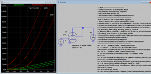
Look at log you see what LTSpice is hinting, the first 2 options can resolve the following errors, and third is required but with reduce number of (SRC) steps to resolve convergence issue because the knee of pentode curve is sharp when Advance Knee option is used by the Paint Tool, the step can not be to large (big number, smaller steps better but slower). You can set these options permanently in LTSpice-> Tools->Control Panel-Spice.
Even LTSpice said it's (Gmin) successful, you should look at other results such as Fourier THD, is it garbled? Somethings maybe compromised, some accuracies maybe scarified, but far better than getting confusing results. If you have mixed models (AYumi and others) then Gmin will affect Ayumi models I noticed.
Early termination of direct N-R iteration.
Direct Newton iteration failed to find .op point. (Use ".option noopiter" to skip.)
Starting Gmin stepping
Gmin = 10
Gmin = 1.07374
Gmin = 0.115292
Gmin = 0.0123794
Gmin = 0.00132923
Gmin = 0.000142725
Gmin = 1.5325e-005
Gmin = 1.6455e-006
Gmin = 1.76685e-007
Gmin = 1.89714e-008
Gmin = 2.03704e-009
Gmin = 2.18725e-010
Gmin = 2.34854e-011
Gmin = 2.52173e-012
Gmin = 2.70769e-013
Gmin = 0
Gmin stepping succeeded in finding the operating point.
Last edited:
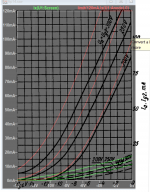
https://katod--anod-ru.translate.go...tr_sl=ru&_x_tr_tl=en&_x_tr_hl=en&_x_tr_pto=sc
These curves are in much better shape.
These curves are in much better shape.
Attachments
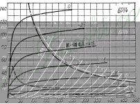
Here is the 6P14 (Chinese ver) pentode model. As no transfer curve is found, it's compared to a Russian's instead:
Code:
**** 6P14 ******************************************
* Created on 02/07/2023 19:52 using paint_kip.jar
* www.dmitrynizh.com/tubeparams_image.htm
* Plate Curves image file: 6p14.png
* Data source link: https://www.sgss8.com/tpdq/20597853
*----------------------------------------------------------------------------------
.SUBCKT 6P14 P G2 G K ; LTSpice tetrode.asy pinout
* .SUBCKT 6P14 P G K G2 ; Koren Pentode Pspice pinout
+ PARAMS: MU=21.57 KG1=534.48 KP=129.82 KVB=43.39 VCT=-0.72 EX=1.33 KG2=563.17 KNEE=170.14 KVC=1.585
+ KLAM=2.5E-8 KLAMG=5.845E-4 KNEE2=20.76 KNEX=667.21  KNK=-0.01716 KNG=0.01932 KNPL=0.625 KNSL=0.1375 KNPR=38.4 KNSR=29
+ CCG=10.8P CGP=0.5P CCP=6.5P VGOFF=-0.6 IGA=0.001 IGB=0.3 IGC=8 IGEX=2
* Vp_MAX=500 Ip_MAX=140 Vg_step=2 Vg_start=0 Vg_count=14
* X_MIN=49 Y_MIN=62 X_SIZE=814 Y_SIZE=562 FSZ_X=1296 FSZ_Y=736 XYGrid=false
* Rp=1400 Vg_ac=20 P_max=13 Vg_qui=-13 Vp_qui=300
* showLoadLine=n showIp=y isDHP=n isPP=n isAsymPP=n isUL=n showDissipLimit=y
* showIg1=y isInputSnapped=y addLocalNFB=n
* XYProjections=n harmonicPlot=y dissipPlot=n
* UL=0.43 EG2=250 gridLevel2=y addKink=y isTanhKnee=y advSigmoid=n
*----------------------------------------------------------------------------------
RE1  7 0  1G    ; DUMMY SO NODE 7 HAS 2 CONNECTIONS
E1   7 0  VALUE=  ; E1 BREAKS UP LONG EQUATION FOR G1.
+{V(G2,K)/KP*LOG(1+EXP((1/MU+(VCT+V(G,K))/SQRT(KVB+V(G2,K)*V(G2,K)))*KP))}
RE2  6 0  1G    ; DUMMY SO NODE 6 HAS 2 CONNECTIONS
E2  6 0  VALUE={(PWR(V(7),EX)+PWRS(V(7),EX))} ; Kg1 times KIT current
RE21 21 0 1
E21  21 0 VALUE={V(6)/KG1*ATAN((V(P,K)+KNEX)/KNEE)*TANH(V(P,K)/KNEE2)} ; Ip with knee but no slope and no kink
RE22 22 0 1 ; E22: kink curr deviation for plate
E22  22 0 VALUE={V(21)*LIMIT(KNK-V(G,K)*KNG,0,0.3)*(-ATAN((V(P,K)-KNPL)/KNSL)+ATAN((V(P,K)-KNPR)/KNSR))}
G1   P  K  VALUE={V(21)*(1+KLAMG*V(P,K))+KLAM*V(P,K) + V(22)}
* Alexander Gurskii screen current, see audioXpress 2/2011, with slope and kink added
RE43 43 K 1G ; Dummy
E43  43 G2 VALUE={0} ; Dummy
G2   43 K  VALUE={V(6)/KG2*(KVC-ATAN((V(P,K)+KNEX)/KNEE)*TANH(V(P,K)/KNEE2))/(1+KLAMG*V(P,K))-V(22)}
RCP  P K  1G     ; FOR CONVERGENCE
C1   K G  {CCG}  ; CATHODE-GRID 1
C2   G P  {CGP}  ; GRID 1-PLATE
C3   K P  {CCP}  ; CATHODE-PLATE
RE23 G 0 1G
GG G K VALUE={(IGA+IGB/(IGC+V(P,K)))*(MU/KG1)*
+(PWR(V(G,K)-VGOFF,IGEX)+PWRS(V(G,K)-VGOFF,IGEX))}
.ENDS
*$
Attachments
Try this 1626 model:
Code:
**** 1626 ** Advanced Grid Current **********************************
* Created on 02/13/2023 00:27 using paint_kit.jar 3.1
* www.dmitrynizh.com/tubeparams_image.htm
* Plate Curves image file: 1626.png
* Data source link:
*----------------------------------------------------------------------------------
.SUBCKT 1626 1 2 3 ; Plate Grid Cathode
+ PARAMS: CCG=3.2P  CGP=4.4P CCP=3.4P
+ MU=5.46 KG1=5291.83 KP=27.47 KVB=558.96 VCT=3.093E-4 EX=1.529
+ VGOFF=-0.9 IGA=0.05983 IGB=7.807 IGC=0.094 IGEX=1.186
* Vp_MAX=500 Ip_MAX=200 Vg_step=8 Vg_start=32 Vg_count=14
* Rp=4000 Vg_ac=55 P_max=5 Vg_qui=-48 Vp_qui=300
* X_MIN=65 Y_MIN=18 X_SIZE=778 Y_SIZE=631 FSZ_X=1296 FSZ_Y=736 XYGrid=false
* showLoadLine=n showIp=y isDHT=n isPP=n isAsymPP=n showDissipLimit=y
* showIg1=y gridLevel2=y isInputSnapped=n
* XYProjections=n harmonicPlot=n dissipPlot=n
*----------------------------------------------------------------------------------
E1 7 0 VALUE={V(1,3)/KP*LOG(1+EXP(KP*(1/MU+(VCT+V(2,3))/SQRT(KVB+V(1,3)*V(1,3)))))}
RE1 7 0 1G  ; TO AVOID FLOATING NODES
G1 1 3 VALUE={(PWR(V(7),EX)+PWRS(V(7),EX))/KG1}
RCP 1 3 1G   ; TO AVOID FLOATING NODES
C1 2 3 {CCG} ; CATHODE-GRID
C2 2 1 {CGP} ; GRID=PLATE
C3 1 3 {CCP} ; CATHODE-PLATE
RE2 2 0 1G
EGC 8 0 VALUE={V(2,3)-VGOFF} ; POSITIVE GRID THRESHOLD
GG 2 3 VALUE={(IGA+IGB/(IGC+V(1,3)))*(MU/KG1)*(PWR(V(8),IGEX)+PWRS(V(8),IGEX))}
.ENDS
*$
Attachments
There is a small alignment error in the grid current of 1626. Here is the correction code:
Code:
**** 1626 ** Advanced Grid Current **********************************
* Created on 02/13/2023 12:51 using paint_kit.jar 3.1
* www.dmitrynizh.com/tubeparams_image.htm
* Plate Curves image file: 1626.png
* Data source link:
*----------------------------------------------------------------------------------
.SUBCKT 1626 1 2 3 ; Plate Grid Cathode
+ PARAMS: CCG=3.2P  CGP=4.4P CCP=3.4P
+ MU=5.46 KG1=5291.83 KP=27.47 KVB=558.96 VCT=3.093E-4 EX=1.529
+ VGOFF=-0.9 IGA=0.03949 IGB=4.606 IGC=0.0329 IGEX=1.139
* Vp_MAX=500 Ip_MAX=200 Vg_step=8 Vg_start=32 Vg_count=14
* Rp=4000 Vg_ac=55 P_max=5 Vg_qui=-48 Vp_qui=300
* X_MIN=65 Y_MIN=18 X_SIZE=778 Y_SIZE=631 FSZ_X=1296 FSZ_Y=736 XYGrid=false
* showLoadLine=n showIp=y isDHT=n isPP=n isAsymPP=n showDissipLimit=y
* showIg1=y gridLevel2=y isInputSnapped=n
* XYProjections=n harmonicPlot=n dissipPlot=n
*----------------------------------------------------------------------------------
E1 7 0 VALUE={V(1,3)/KP*LOG(1+EXP(KP*(1/MU+(VCT+V(2,3))/SQRT(KVB+V(1,3)*V(1,3)))))}
RE1 7 0 1G  ; TO AVOID FLOATING NODES
G1 1 3 VALUE={(PWR(V(7),EX)+PWRS(V(7),EX))/KG1}
RCP 1 3 1G   ; TO AVOID FLOATING NODES
C1 2 3 {CCG} ; CATHODE-GRID
C2 2 1 {CGP} ; GRID=PLATE
C3 1 3 {CCP} ; CATHODE-PLATE
RE2 2 0 1G
EGC 8 0 VALUE={V(2,3)-VGOFF} ; POSITIVE GRID THRESHOLD
GG 2 3 VALUE={(IGA+IGB/(IGC+V(1,3)))*(MU/KG1)*(PWR(V(8),IGEX)+PWRS(V(8),IGEX))}
.ENDS
*$
Attachments
Last edited:
- Home
- Amplifiers
- Tubes / Valves
- Vacuum Tube SPICE Models