Always found them interesting and bought multiples of different versions at a buck or two each years ago. The 954 curves look promising for a front end? Mic pre? Phono? BTW the 9002 model posted earlier in this thread is a repackaging of the very nice 955 acorn.
Re: the curves I discovered my window manger was positioning the advanced knee controls off screen so taking another run at optimising the fit.
Re: the curves I discovered my window manger was positioning the advanced knee controls off screen so taking another run at optimising the fit.
Here is GE 6DK6 (not typo for 6KD6) model:
Code:
**** 6DK6 ******************************************
* Created on 09/24/2022 17:22 using paint_kip.jar
* www.dmitrynizh.com/tubeparams_image.htm
* Plate Curves image file: 6dk6p.png
* Data source link: <plate curves URL>
*--------------------------------------------------------------posted--------------------
.SUBCKT 6DK6 P G2 G K ; LTSpice tetrode.asy pinout
* .SUBCKT 6DK6P P G K G2 ; Koren Pentode Pspice pinout
+ PARAMS: MU=56.27 KG1=564.84 KP=134.14 KVB=791.85 VCT=0.0463 EX=1.608 KG2=1206.33 KNEE=5.04 KVC=2.328
+ KLAM=8.5E-8 KLAMG=9.24E-6  KD=0.987 KC=4.318 KR1=0.01036 KR2=0.2806 KVBG=2.133 KB1=6.931 KB2=1.84 KB3=2 KB4=0.2279 KVBGI=2.512 KNK=-0.05576 KNG=0.04411 KNPL=0.3093 KNSL=0.001389 KNPR=9.6 KNSR=42.59
+ CCG=6.3P CGP=0.02P CCP=1.9P VGOFF=-0.6 IGA=0.001 IGB=0.3 IGC=8 IGEX=2
* Vp_MAX=500 Ip_MAX=28 Vg_step=1 Vg_start=0 Vg_count=9
* X_MIN=45 Y_MIN=35 X_SIZE=743 Y_SIZE=520 FSZ_X=1296 FSZ_Y=736 XYGrid=false
* Rp=1400 Vg_ac=20 P_max=2.5 Vg_qui=-4 Vp_qui=300
* showLoadLine=n showIp=y isDHP=n isPP=n isAsymPP=n isUL=n showDissipLimit=y
* showIg1=y isInputSnapped=y addLocalNFB=n
* XYProjections=n harmonicPlot=y dissipPlot=n
* UL=0.43 EG2=125 gridLevel2=y addKink=y isTanhKnee=n advSigmoid=y
*----------------------------------------------------------------------------------
RE1  7 0  1G    ; DUMMY SO NODE 7 HAS 2 CONNECTIONS
E1   7 0  VALUE=  ; E1 BREAKS UP LONG EQUATION FOR G1.
+{V(G2,K)/KP*LOG(1+EXP((1/MU+(VCT+V(G,K))/SQRT(KVB+V(G2,K)*V(G2,K)))*KP))}
RE2  6 0  1G    ; DUMMY SO NODE 6 HAS 2 CONNECTIONS
E2  6 0  VALUE={(PWR(V(7),EX)+PWRS(V(7),EX))} ; Kg1 times KIT current
E4   8 0  VALUE={V(P,K)/KNEE/(KVBGI+V(6)*KVBG)}
E5  81 0  VALUE={PWR(V(8),KB1)}
E6  82 0  VALUE={PWR(V(8),KB2)}
E7  83 0  VALUE={PWR(V(8),KB3)}
E8   9 0  VALUE={PWR(1-EXP(-V(81)*(KC+KR1*V(82))/(KD+KR2*V(83))),KB4)*1.5708}
RE4  8 0  1
RE5 81 0  1
RE6 82 0  1
RE7 83 0  1
RE8  9 0  1
RE21 21 0 1
E21  21 0 VALUE={V(6)/KG1*V(9)} ; Ip with knee but no slope and no kink
RE22 22 0 1 ; E22: kink curr deviation for plate
E22  22 0 VALUE={V(21)*LIMIT(KNK-V(G,K)*KNG,0,0.3)*(-ATAN((V(P,K)-KNPL)/KNSL)+ATAN((V(P,K)-KNPR)/KNSR))}
G1   P K  VALUE={V(21)*(1+KLAMG*V(P,K))+KLAM*V(P,K) + V(22)}
G2   G2 K  VALUE={V(6)/KG2*(KVC-V(9))/(1+KLAMG*V(P,K)) - V(22)}
RCP  P K  1G     ; FOR CONVERGENCE
C1   K G  {CCG}  ; CATHODE-GRID 1
C2   G P  {CGP}  ; GRID 1-PLATE
C3   K P  {CCP}  ; CATHODE-PLATE
RE23 G 0 1G
GG G K VALUE={(IGA+IGB/(IGC+V(P,K)))*(MU/KG1)*
+(PWR(V(G,K)-VGOFF,IGEX)+PWRS(V(G,K)-VGOFF,IGEX))}
.ENDS
*$
Attachments

I think this one is the same at the 6EZ8?Hi all
A further model of mine. This time the 19EZ8, one of the very rare triple triodes.
This triode was quite tricky to fit, because the plate resistance shows a certain drop when a larger grid current is present.
However, this is not of relevance for most applications.
Have fun!
BR Adrian
Which seems to pop-up on ebay every now and than.
There seems to be even a 12EZ8, although no official datasheets.
Interesting tube.
The connection are so unfortunate from an audio point of view.
Would be great if they just connected one of the tube as a cathodyne, directly connecting the grid to the anode of one of the other triodes, leaving the cathode. Instead of connecting that one to the heater.
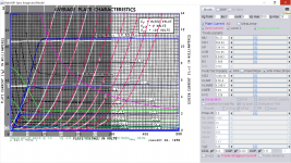
954 acorn model from RCA datasheet.
Code:
** 954 ****************************************
*----------------------------------------------------------------------------------
- Created on 09/25/2022 12:16 using paint_kip.jar
- www.dmitrynizh.com/tubeparams_image.htm
- Plate Curves image file: 954.jpg
- Data source link: <plate curves URL>
.SUBCKT 954 P G2 G K ; LTSpice tetrode.asy pinout
* .SUBCKT 954 P G K G2 ; Koren Pentode Pspice pinout
- PARAMS: MU=22 KG1=3870.62 KP=93 KVB=0.06238 VCT=0.006407 EX=1.574 KG2=23.98 KNEE=23.96 KVC=2.57
- KLAM=1.321e-9 KLAMG=4.631e-8 KNEE2=13.5 KNEX=256.5 KNK=-0.044 KNG=0.006
- CCG=3.4P CGP=0.007P CCP=3P RGI=2000.0
*----------------------------------------------------------------------------------
- Vp_MAX=400 Ip_MAX=10 Vg_step=0.5 Vg_start=0 Vg_count=11
- X_MIN=129 Y_MIN=113 X_SIZE=1217 Y_SIZE=745 FSZ_X=1918 FSZ_Y=996 XYGrid=false
- Rp=11421 Vg_ac=0.039 P_max=0.5 Vg_qui=-1.128 Vp_qui=75.48
- showLoadLine=n showIp=y isDHP=n isPP=n isAsymPP=n isUL=n showDissipLimit=y
- showIg1=n isInputSnapped=n addLocalNFB=n
- XYProjections=n harmonicPlot=y dissipPlot=y
- UL=0.43 EG2=100 gridLevel2=n addKink=n isTanhKnee=y advSigmoid=n
RE1 7 0 1G ; DUMMY SO NODE 7 HAS 2 CONNECTIONS
E1 7 0 VALUE= ; E1 BREAKS UP LONG EQUATION FOR G1.
+{V(G2,K)/KP*LOG(1+EXP((1/MU+(VCT+V(G,K))/SQRT(KVB+V(G2,K)*V(G2,K)))*KP))}
RE2 6 0 1G ; DUMMY SO NODE 6 HAS 2 CONNECTIONS
E2 6 0 VALUE={(PWR(V(7),EX)+PWRS(V(7),EX))} ; Kg1 times KIT current
G1 P K VALUE={V(6)/KG1*ATAN((V(P,K)+KNEX)/KNEE)TANH(V(P,K)/KNEE2)(1+KLAMG*V(P,K))+KLAM*V(P,K)}
* Alexander Gurskii screen current, see audioXpress 2/2011
RE4K 4K K 1G ; Dummy, per Alex request
E4K 4K 4 VALUE={0} ; Dummy, per Alex request
G4K 4K K VALUE={V(6)/KG2*(KVC-ATAN((V(P,K)+KNEX)/KNEE)*TANH(V(P,K)/KNEE2))/(1+KLAMG*V(P,K))}
RCP P K 1G ; FOR CONVERGENCE
C1 K G {CCG} ; CATHODE-GRID 1
C2 G P {CGP} ; GRID 1-PLATE
C3 K P {CCP} ; CATHODE-PLATE
R1 G 5 {RGI} ; FOR GRID CURRENT
D3 5 K DX ; FOR GRID CURRENT }
.MODEL DX D(IS=1N RS=1 CJO=10PF TT=1N)
.ENDS
*$
Attachments
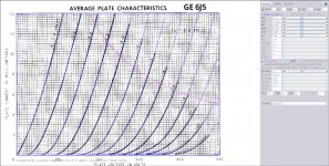
GE 6J5 triode
** 6J5 ****************************************
*----------------------------------------------------------------------------------
- Created on 09/28/2022 13:18 using paint_kit.jar 3.1
- www.dmitrynizh.com/tubeparams_image.htm
- Plate Curves image file: 6J5.jpg
- Data source link:
.SUBCKT TRIODE_6J5 1 2 3 ; Plate Grid Cathode
- PARAMS: CCG=3.4P CGP=3.4P CCP=3.6P RGI=2000
- MU=21.27 KG1=1513.04 KP=157.42 KVB=572.06 VCT=0.1698 EX=1.354
*----------------------------------------------------------------------------------
- Vp_MAX=500 Ip_MAX=14 Vg_step=2 Vg_start=0 Vg_count=13
- Rp=156288 Vg_ac=3.065 P_max=2.5 Vg_qui=-7.446 Vp_qui=214.7
- X_MIN=95 Y_MIN=76 X_SIZE=1184 Y_SIZE=831 FSZ_X=1918 FSZ_Y=996 XYGrid=false
- showLoadLine=n showIp=y isDHT=n isPP=n isAsymPP=n showDissipLimit=y
- showIg1=n gridLevel2=n isInputSnapped=n
- XYProjections=y harmonicPlot=y dissipPlot=n
E1 7 0 VALUE={V(1,3)/KP*LOG(1+EXP(KP*(1/MU+(VCT+V(2,3))/SQRT(KVB+V(1,3)*V(1,3)))))}
RE1 7 0 1G ; TO AVOID FLOATING NODES
G1 1 3 VALUE={(PWR(V(7),EX)+PWRS(V(7),EX))/KG1}
RCP 1 3 1G ; TO AVOID FLOATING NODES
C1 2 3 {CCG} ; CATHODE-GRID
C2 2 1 {CGP} ; GRID=PLATE
C3 1 3 {CCP} ; CATHODE-PLATE
D3 5 3 DX ; POSITIVE GRID CURRENT
R1 2 5 {RGI} ; POSITIVE GRID CURRENT
.MODEL DX D(IS=1N RS=1 CJO=10PF TT=1N)
.ENDS
*$
Attachments
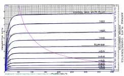
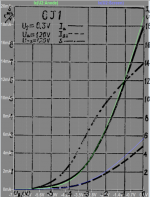
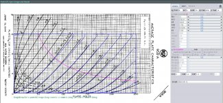
6J1 pentode model:
Code:
*** 6J1_P *********************************good2*********
* Created on 10/07/2022 22:25 using paint_kip.jar
* www.dmitrynizh.com/tubeparams_image.htm
* Plate Curves image file: 6j1-p.png
* Data source link: <plate curves URL>
*----------------------------------------------------------------------------------
.SUBCKT 6J1_P P G2 G K ; LTSpice tetrode.asy pinout
* .SUBCKT 6J1_P P G K G2 ; Koren Pentode Pspice pinout
+ PARAMS: MU=36.76 KG1=493.39 KP=154.29 KVB=924.49 VCT=-0.1558 EX=1.184 KG2=695.44 KNEE=11.77 KVC=1.571
+ KLAM=7.631E-16 KLAMG=2.764E-4 KNEE2=14.95 KNEX=22.06  KNK=0.7192 KNG=0.07263 KNPL=0.2412 KNSL=572.38 KNPR=456.84 KNSR=629.57
+ CCG=4.3P CGP=0.02P CCP=2.35P VGOFF=-0.2475 IGA=6.2E-4 IGB=0.195 IGC=7.6 IGEX=2
* Vp_MAX=250 Ip_MAX=20 Vg_step=1 Vg_start=0 Vg_count=9
* X_MIN=59 Y_MIN=11 X_SIZE=779 Y_SIZE=637 FSZ_X=1296 FSZ_Y=736 XYGrid=false
* Rp=1400 Vg_ac=20 P_max=1.8 Vg_qui=-4 Vp_qui=300
* showLoadLine=n showIp=y isDHP=n isPP=n isAsymPP=n isUL=n showDissipLimit=y
* showIg1=y isInputSnapped=y addLocalNFB=n
* XYProjections=n harmonicPlot=y dissipPlot=n
* UL=0.43 EG2=120 gridLevel2=y addKink=y isTanhKnee=y advSigmoid=n
*----------------------------------------------------------------------------------
RE1  7 0  1G    ; DUMMY SO NODE 7 HAS 2 CONNECTIONS
E1   7 0  VALUE=  ; E1 BREAKS UP LONG EQUATION FOR G1.
+{V(G2,K)/KP*LOG(1+EXP((1/MU+(VCT+V(G,K))/SQRT(KVB+V(G2,K)*V(G2,K)))*KP))}
RE2  6 0  1G    ; DUMMY SO NODE 6 HAS 2 CONNECTIONS
E2  6 0  VALUE={(PWR(V(7),EX)+PWRS(V(7),EX))} ; Kg1 times KIT current
RE21 21 0 1
E21  21 0 VALUE={V(6)/KG1*ATAN((V(P,K)+KNEX)/KNEE)*TANH(V(P,K)/KNEE2)} ; Ip with knee but no slope and no kink
RE22 22 0 1 ; E22: kink curr deviation for plate
E22  22 0 VALUE={V(21)*LIMIT(KNK-V(G,K)*KNG,0,0.3)*(-ATAN((V(P,K)-KNPL)/KNSL)+ATAN((V(P,K)-KNPR)/KNSR))}
G1   P  K  VALUE={V(21)*(1+KLAMG*V(P,K))+KLAM*V(P,K) + V(22)}
* Alexander Gurskii screen current, see audioXpress 2/2011, with slope and kink added
RE43 43 K 1G ; Dummy
E43  43 G2 VALUE={0} ; Dummy
G2   43 K  VALUE={V(6)/KG2*(KVC-ATAN((V(P,K)+KNEX)/KNEE)*TANH(V(P,K)/KNEE2))/(1+KLAMG*V(P,K))-V(22)}
RCP  P K  1G     ; FOR CONVERGENCE
C1   K G  {CCG}  ; CATHODE-GRID 1
C2   G P  {CGP}  ; GRID 1-PLATE
C3   K P  {CCP}  ; CATHODE-PLATE
RE23 G 0 1G
GG G K VALUE={(IGA+IGB/(IGC+V(P,K)))*(MU/KG1)*
+(PWR(V(G,K)-VGOFF,IGEX)+PWRS(V(G,K)-VGOFF,IGEX))}
.ENDS
*$
Attachments
RCA 958A, a DHT acorn.
** 958A ****************************************
*----------------------------------------------------------------------------------
- Created on 10/09/2022 14:40 using paint_kit.jar 3.1
- www.dmitrynizh.com/tubeparams_image.htm
- Plate Curves image file: 958A.jpg
- Data source link:
.SUBCKT TRIODE_958A 1 2 3 ; Plate Grid Cathode
- PARAMS: CCG=3P CGP=1.4P CCP=1.9P RGI=2000
- MU=12 KG1=3782.61 KP=166.61 KVB=1.793 VCT=0.02306 EX=1.329
*----------------------------------------------------------------------------------
- Vp_MAX=250 Ip_MAX=12 Vg_step=2 Vg_start=0 Vg_count=10
- Rp=31500 Vg_ac=0.0927 P_max=0.6 Vg_qui=-1.62 Vp_qui=83.11
- X_MIN=104 Y_MIN=235 X_SIZE=940 Y_SIZE=457 FSZ_X=1918 FSZ_Y=863 XYGrid=false
- showLoadLine=n showIp=y isDHT=n isPP=n isAsymPP=n showDissipLimit=y
- showIg1=n gridLevel2=n isInputSnapped=n
- XYProjections=y harmonicPlot=y dissipPlot=n
E1 7 0 VALUE={V(1,3)/KP*LOG(1+EXP(KP*(1/MU+(VCT+V(2,3))/SQRT(KVB+V(1,3)*V(1,3)))))}
RE1 7 0 1G ; TO AVOID FLOATING NODES
G1 1 3 VALUE={(PWR(V(7),EX)+PWRS(V(7),EX))/KG1}
RCP 1 3 1G ; TO AVOID FLOATING NODES
C1 2 3 {CCG} ; CATHODE-GRID
C2 2 1 {CGP} ; GRID=PLATE
C3 1 3 {CCP} ; CATHODE-PLATE
D3 5 3 DX ; POSITIVE GRID CURRENT
R1 2 5 {RGI} ; POSITIVE GRID CURRENT
.MODEL DX D(IS=1N RS=1 CJO=10PF TT=1N)
.ENDS
*$
Attachments
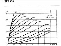
Try this SRS326 model:
Code:
**** SRS326 ** Advanced Grid Current ********************8**************
* Created on 10/14/2022 11:05 using paint_kit.jar 3.1
* www.dmitrynizh.com/tubeparams_image.htm
* Plate Curves image file: SRS326.jpg
* Data source link:
*----------------------------------------------------------------------------------
.SUBCKT SRS326 1 2 3 ; Plate Grid Cathode
+ PARAMS: CCG=7P  CGP=4.4P CCP=0.7P
+ MU=27.43 KG1=5067.64 KP=265.38 KVB=30243.47 VCT=-0.008575 EX=1.656
+ VGOFF=-0.6 IGA=3.465E-4 IGB=0.08505 IGC=11.17 IGEX=1.588
* Vp_MAX=4000 Ip_MAX=2800 Vg_step=20 Vg_start=200 Vg_count=12
* Rp=4000 Vg_ac=55 P_max=420 Vg_qui=-48 Vp_qui=300
* X_MIN=78 Y_MIN=46 X_SIZE=736 Y_SIZE=506 FSZ_X=1296 FSZ_Y=736 XYGrid=false
* showLoadLine=n showIp=y isDHT=n isPP=n isAsymPP=n showDissipLimit=y
* showIg1=y gridLevel2=y isInputSnapped=n
* XYProjections=n harmonicPlot=n dissipPlot=n
*----------------------------------------------------------------------------------
E1 7 0 VALUE={V(1,3)/KP*LOG(1+EXP(KP*(1/MU+(VCT+V(2,3))/SQRT(KVB+V(1,3)*V(1,3)))))}
RE1 7 0 1G  ; TO AVOID FLOATING NODES
G1 1 3 VALUE={(PWR(V(7),EX)+PWRS(V(7),EX))/KG1}
RCP 1 3 1G   ; TO AVOID FLOATING NODES
C1 2 3 {CCG} ; CATHODE-GRID
C2 2 1 {CGP} ; GRID=PLATE
C3 1 3 {CCP} ; CATHODE-PLATE
RE2 2 0 1G
EGC 8 0 VALUE={V(2,3)-VGOFF} ; POSITIVE GRID THRESHOLD
GG 2 3 VALUE={(IGA+IGB/(IGC+V(1,3)))*(MU/KG1)*(PWR(V(8),IGEX)+PWRS(V(8),IGEX))}
.ENDS
*$
Attachments
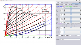
SRS326 model with grid current adjust:
Code:
**** SRS326 ** Advanced Grid Current ***********************9***********
* Created on 10/14/2022 14:44 using paint_kit.jar 3.1
* www.dmitrynizh.com/tubeparams_image.htm
* Plate Curves image file: SRS326.jpg
* Data source link:
*----------------------------------------------------------------------------------
.SUBCKT SRS326 1 2 3 ; Plate Grid Cathode
+ PARAMS: CCG=7P  CGP=4.4P CCP=0.7P
+ MU=26.81 KG1=4334.86 KP=124.38 KVB=26916.69 VCT=1.16 EX=1.622
+ VGOFF=1 IGA=8.575E-7 IGB=0.1424 IGC=386.78 IGEX=2.391
* Vp_MAX=3500 Ip_MAX=2800 Vg_step=20 Vg_start=200 Vg_count=12
* Rp=4000 Vg_ac=55 P_max=420 Vg_qui=-48 Vp_qui=300
* X_MIN=45 Y_MIN=6 X_SIZE=769 Y_SIZE=605 FSZ_X=1296 FSZ_Y=736 XYGrid=false
* showLoadLine=n showIp=y isDHT=n isPP=n isAsymPP=n showDissipLimit=y
* showIg1=y gridLevel2=y isInputSnapped=n
* XYProjections=n harmonicPlot=n dissipPlot=n
*----------------------------------------------------------------------------------
E1 7 0 VALUE={V(1,3)/KP*LOG(1+EXP(KP*(1/MU+(VCT+V(2,3))/SQRT(KVB+V(1,3)*V(1,3)))))}
RE1 7 0 1G  ; TO AVOID FLOATING NODES
G1 1 3 VALUE={(PWR(V(7),EX)+PWRS(V(7),EX))/KG1}
RCP 1 3 1G   ; TO AVOID FLOATING NODES
C1 2 3 {CCG} ; CATHODE-GRID
C2 2 1 {CGP} ; GRID=PLATE
C3 1 3 {CCP} ; CATHODE-PLATE
RE2 2 0 1G
EGC 8 0 VALUE={V(2,3)-VGOFF} ; POSITIVE GRID THRESHOLD
GG 2 3 VALUE={(IGA+IGB/(IGC+V(1,3)))*(MU/KG1)*(PWR(V(8),IGEX)+PWRS(V(8),IGEX))}
.ENDS
*$
Attachments
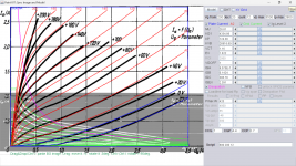
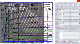
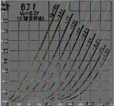
Hi all
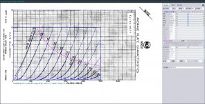
To be honest, the SRS326 datasheet curves from RFT are really disappointing. Luckely, there are also curves from VEB Phönix, and those are of much better quality. But those guys used an unusual axis arrangement, so I had to rotate and flip the chart to get it in the usual form.
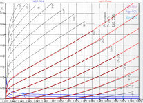
There is also a separate grid current graph, also in a very unusual format. Here, I could a least extract some single grid current points, as a basis for a rough grid model.
I hope the resulting tube model is a bit more precise...
BR Adrian
To be honest, the SRS326 datasheet curves from RFT are really disappointing. Luckely, there are also curves from VEB Phönix, and those are of much better quality. But those guys used an unusual axis arrangement, so I had to rotate and flip the chart to get it in the usual form.
There is also a separate grid current graph, also in a very unusual format. Here, I could a least extract some single grid current points, as a basis for a rough grid model.
I hope the resulting tube model is a bit more precise...
BR Adrian
Code:
*SRS326 LTspice model based on the generic triode model from Adrian Immler, version i5
*A version log is at the end of this file
*Params fitted to the VEB Phönix datasheet values by Adrian Immler, Oct 2022
*This model is accurate for Vg up to 60V.
*The high fit quality is presented at adrianimmler.simplesite.com
*History's best of tube describing art (plus some new ideas) is merged to this new approach.
*@ neg. Vg, Ia accuracy is similar to Koren models, and unrivaled for remote cutoff triodes
*@ small neg. Vg, the "Anlauf" current is considered.
*@ pos. Vg, Ig and Ia accuracy is on an unrivaled level (including neg. Va range!)
*This offers new simulation possibilities like grid resistor bias, backward plate modulated stages,
*Audion radio circuits, low voltage amps, guitar distortion stages or pulsed stages.
*              i5 version
*              |  anode (plate)
*              |  | grid
*              |  | | cathode
*              |  | | |
.subckt SRS326.i5 A G K
+ params:
*Parameters for space charge current Is (100% assigned to Ia @ Vg < 0)
+ mu   = 31.5  ;Determines the voltage gain @ constant Ia
+ rad  = 9k5   ;Differential anode resistance, set @ Iad and Vg=0V
+ Vct  = 3     ;Offsets the Ia-traces on the Va axis. Electrode material's contact potential
+ kp   = 280   ;Mimics the island effect
+ xs   = 1.45  ;Determines the curve of the Ia traces. Typically between 1.2 and 1.8
+ kIsr = 1m6   ;Va-independent part of the Is reduction when grid current occurs
+ kvdg  = 20k  ;Va-dependent part of the Is reduction when grid current occurs
*
*Parameters for assigning the space charge current to Ia and Ig @ Vg > 0
+ kB   = 0.03  ;Describes how fast Ia drops to zero when Va approaches zero.
+ radl = 200   ;Differential resistance for the Ia emission limit @ very small Va and Vg > 0
+ tsh  = 8     ;Ia transmission sharpness from 1st to 2nd Ia area. Keep between 3 and 20. Start with 20.
+ xl   = 1.3   ;Exponent for the emission limit
*
*Parameters of the grid-cathode vacuum diode
+ kg = 6k      ;Inverse scaling factor for the Va independent part of Ig (caution - interacts with xg!)
+ Vctg = -6    ;Offsets the log Ig-traces on the Vg axis. Electrode material's contact potential
+ xg   = 1.5   ;Determines the curve of the Ig slope versus (positive) Vg and Va >> 0
+ VT   = 0.15  ;Log(Ig) slope @ Vg<0. VT=k/q*Tk (cathodes absolute temp, typically 1770K for thoriated tungsten)
+ rTr  = 0.8   ;ratio of VT for Igr. Typically 0.8
+ kVT=0        ;Va dependent koeff. of VT
+ gft1 = 0     ;reduces the steering voltage around Vg=-Vg0, for finetuning purposes
+ gft1a= 0     ;reduces the steering voltage around Vg=-Vg0. Effect decreases with 1/(1+kB*Va)
+ gft2 = 0     ;finetunes the Igr drop @ increasing Va and around Vg=-Vg0
*
*Parameters for the caps
+ cag  = 4p4   ;From datasheet (values from the first triode)
+ cak  = 0p7   ;From datasheet (values from the first triode)
+ cgk  = 7p0   ;From datasheet (values from the first triode)
*
*special purpose parameters
+ os = 1       ;Overall scaling factor, if a user wishes to simulate manufacturing tolerances
+ murc = 10    ;Mu of the remote cutoff triode
+ ksrc = 5k85  ;Inverse Iarc gain factor for the remote cutoff triode
+ kprc = 55    ;Mimics the island effect for the remote cutoff triode
+ Vbatt = 0    ;heater battery voltage for direct heated battery triodes
+ Vdrmax = 0.93;max voltage of internal Vg drop, for convergence improvements
*
*Calculated parameters
+ Iad = {100/rad} ;Ia where the anode a.c. resistance is set according to rad.
+ ks = {pow(mu/(rad*xs*Iad**(1-1/xs)),-xs)} ;Reduces the unwished xs influence to the Ia slope
+ ksnom = {pow(mu/(rad*1.5*Iad**(1-1/1.5)),-1.5)} ;Sub-equation for calculating Vg0
+ Vg0 = {Vct + (Iad*ks)**(1/xs) - (Iad*ksnom)**(2/3)} ;Reduces the xs influence to Vct.
+ kl = {pow(1/(radl*xl*Ild**(1-1/xl)),-xl)} ;Reduces the xl influence to the Ia slope @ small Va
+ Ild = {sqrt(radl)*1m} ;Current where the Il a.c. resistance is set according to radl.
*
*Space charge current model
Rak A K 100G ;avoids "floating net" errors
Bft   ft 0 V=1/(1+pow(2*abs(v(G,Ki)+Vg0),3)) ;an auxiliary voltage to finetune the triode around Vg=-Vg0
Bggi GGi 0 V=(v(Gi,Ki)+Vg0)*(1/(1+kIsr*max(0, v(G,Ki)+Vg0))) - gft1*v(ft) - gft1a*v(ft)/(1+kB*v(Ahc)) ;Effective internal grid voltage.
Bahc Ahc 0 V=uramp(v(A,Ki)) ;Anode voltage, hard cut to zero @ neg. value
Bst   St 0 V=uramp(max(v(GGi)+v(A,Ki)/(mu), v(A,Ki)/kp*ln(1+exp(kp*(1/mu+v(GGi)/(1+v(Ahc)))))));Steering volt.
Bs    Ai Ki I=os/ks*pow(v(St),xs) ;Langmuir-Childs law for the space charge current Is
*Bstrc Strc 0 V=uramp(max(v(GGi)+v(Ahc)/(murc), v(Ahc)/kprc*ln(1+exp(kprc*(1/murc+v(GGi)/(1+v(Ahc)))))));FOR REMOTE CUTOFF TUBES ONLY
*Bsrc   Ai Ki I=os/ksrc*pow(v(Strc),xs) ;FOR REMOTE CUTOFF TUBES ONLY
*
*Anode current limit @ small Va
.func smin(z,y,k) {pow(pow(z+1f, -k)+pow(y+1f, -k), -1/k)} ;Min-function with smooth trans.
.func ssmin(z,y,k) {min(min(z,y), smin(z*1.003,y*1.003,k))};smin-function which suppresses small residual differences
Ra  A Ai 1
Bgl Gi A I=uramp(i(Ra)-ssmin(1/kl*pow(v(Ahc),xl),i(Ra),tsh)) ;Ia emission limit
*
*Grid model
Rgk G K 10G ;avoids "floating net" errors
Bvdg G Gi I=1/kvdg*pow(v(G,Gi),1.5) ;Reduces the internal effective grid voltage when Ig rises
Bcoh G Gi I=pow(uramp(v(G,Gi)-Vdrmax),2) ;A convergence help which softly limits the internal Vg voltage drop.
Rgip G Gi 1G ;avoids some warnings
.func fVT() {VT*exp(-kVT*sqrt(v(A,Ki)))}
.func Ivd(Vvd, kvd, xvd, VTvd)  {if(Vvd < 3, 1/kvd*pow(VTvd*xvd*ln(1+exp(Vvd/VTvd/xvd)),xvd), 1/kvd*pow(Vvd, xvd))} ;Vacuum diode function
Bgvd G Ki I=Ivd(v(G,Ki) + Vctg + min(0,v(A,Ki)/mu), kg/os, xg, fVT()) ;limits the internal Vg for convergence reasons
Bstn Stn 0 V=v(GGi)+min(0,v(A,Ki))/mu ;special steering voltage, sensitive to negative Anode voltages only
Bgr Gi Ai I= ivd(v(Stn),ks/os, xs, rTr*fVT())/(1+(kB+v(ft)*gft2)*v(Ahc));Is reflection to grid when Va approaches zero
*Bgr Gi Ai I=(ivd(v(Stn),ks/os, xs, rTr*fVT())+os/ksrc*pow(v(GGi),xs))/(1+(kB+v(ft)*gft2)*v(Ahc));FOR REMOTE CUTOFF TUBES ONLY
Bs0 Ai Ki  I=uramp(ivd(v(Stn),ks/os, xs, rTr*fVT()) - os/ks*pow(v(Stn),xs))
Bbatt Ki K V=Vbatt/2 ;for battery heated triodes; Offsets the average cathode potential to the half heater battery voltage
*
*Caps
C1 A G {cag}
C2 A K {cak}
C3 G K {cgk}
.ends
*
*Version log
*i1 :Initial version
*i2 :Pin order changed to the more common order A G K (Thanks to Markus Gyger for his tip)
*i3 :bugfix of the Ivd-function: now also usable for larger Vvd
*i4: Rgi replaced by a virtual vacuum diode (better convergence). ft1 deleted (no longer needed)
;2 new params for Ig finetuning @ Va and Vg near zero. New overall scaling factor os for aging etc.
*i5: improved convergence performance. PosVg/NegVa area now correct. Also accurate now for remote cutoff triodes!
Attachments
An alternate model for the 9002/955. Ayumi's version acted odd for me which may have been at this end. The SUBCKT name is 9002_rdf to separate it from earlier posts.
** 9002 ****************************************
*----------------------------------------------------------------------------------
- Created on 10/13/2022 22:10 using paint_kit.jar 3.1
- www.dmitrynizh.com/tubeparams_image.htm
- Plate Curves image file: 9002.jpg
- Data source link:
.SUBCKT 9002_rdf 1 2 3 ; Plate Grid Cathode
- PARAMS: CCG=1P CGP=1.4P CCP=0.6P RGI=2000
- MU=24.9 KG1=2065.7 KP=197.57 KVB=1555.78 VCT=0.5604 EX=1.428
*----------------------------------------------------------------------------------
- Vp_MAX=500 Ip_MAX=12 Vg_step=2 Vg_start=0 Vg_count=12
- Rp=25200 Vg_ac=0.07796 P_max=1.6 Vg_qui=-1.867 Vp_qui=147.5
- X_MIN=123 Y_MIN=228 X_SIZE=818 Y_SIZE=494 FSZ_X=1918 FSZ_Y=971 XYGrid=false
- showLoadLine=n showIp=y isDHT=n isPP=n isAsymPP=n showDissipLimit=y
- showIg1=n gridLevel2=n isInputSnapped=n
- XYProjections=n harmonicPlot=y dissipPlot=n
E1 7 0 VALUE={V(1,3)/KP*LOG(1+EXP(KP*(1/MU+(VCT+V(2,3))/SQRT(KVB+V(1,3)*V(1,3)))))}
RE1 7 0 1G ; TO AVOID FLOATING NODES
G1 1 3 VALUE={(PWR(V(7),EX)+PWRS(V(7),EX))/KG1}
RCP 1 3 1G ; TO AVOID FLOATING NODES
C1 2 3 {CCG} ; CATHODE-GRID
C2 2 1 {CGP} ; GRID=PLATE
C3 1 3 {CCP} ; CATHODE-PLATE
D3 5 3 DX ; POSITIVE GRID CURRENT
R1 2 5 {RGI} ; POSITIVE GRID CURRENT
.MODEL DX D(IS=1N RS=1 CJO=10PF TT=1N)
.ENDS
*$
Attachments
My Win10 hiccups when I run the latest LTspice program. Tried copying the tube directory to no avail. Win banner keeps arriving at a files load point "cannot update. abort and re-update". What am I doing incorrct ? I cannot count the number of times I´ve been though this process.
Anyone give any tips ?
ric
Anyone give any tips ?
ric
I think by default, LTspice tries to create the \lib\ folder in \Program Files X86\. However, that is a protected folder, and you may have trouble writing to it. What I do is, during installation, tell LTspice to create the \lib\ folder in \Documents\. I also put my \LTspice Projects\ folder under \Documents\. That way there's no trouble with permissions to write to those folders. I hope that helps.
On my system LTspice XVII also created that same directory structure under the My Documents folder so that there would be so privileges issues. A clean install did not create any folders under Program File X86. However, it did duplicate the directory structure in the 64-bit Program Files folder since I installed the 64-bit version.
I had a similar problem similar to Rich once, and I fixed it by uninstalling and reinstalling, with deleting the contents of the files under the My Documents directory structure before reinstalling. I suspect that there were some corrupted files and the updater was not able to overwrite them, but this is just a guess.
I have a "User" folder under \lib\sub and \lib\sym for my user-installed models and symbols respectively so I was able to delete everything else without throwing away my own models and symbols. But if you have your own files stored in the same directories as the built-in files you will probably not be able to do this. Just a caution.
Thanks for all replies; I will attack this by completely opening a new folder in c: program files but firstly have to make sure and delete any previous Spice file clones involving Onedrive, which for me has been a creator of other issues.. I also wondered if any tube models also simulate B9A pentode strapped as triode analysis, as this is one of my favourites.
Check in the Spice Control Panel the Priority setting. In the previous version it's set to high, now median.
If you run "Photo Apps", check CPU utilization (20%-35%) for the process "Shell Infrastructure Host", after Photo App has been running for some times and "Shell Infrastructure Host" still continue to consume CPU even after Photo has quit. The result is slow down of LTSpice sim and fan speed increased.
I'm running WIn11 with lastest update, this problem still exists, but is a lot faster than any previous version. I don't run Photo App any more.
Edition Windows 11 Home Single Language
Version 22H2
Installed on 10/11/2022
OS build 22621.674
Experience Windows Feature Experience Pack 1000.22634.1000.0
Well, tried most of the recommendations and this is the log jam I continually get. see pic
Although I´m running Win10 Home Ed 21H2 on an Acer Aspire, I´ve had loads of issues with Windows 10, refreshed it countless times and continues to be unreliable. The annoyance of having to reload that Spice version takes a good 1/4 hr on copper, even though I prioritize the uploads to another time.
My slide-rules are just the otherside of the bench.
Best bet is to try another simulation program from another vendor that is less demanding for Win10, but there must be loads out there running Spice quite successfully. I can´t believe it´s the upload speed that creates problem issues.
rich
To update LTSpice just click on "Tools->Sync release", so you do that as many times as quickly as you can. I update just now only a few mins, below is Changelog.txt Maybe you can tell where are the incomplete modules and do further investigations.
PS just share that CPU usage is something to watch out, of course it's not the cause to your problem.
I got a problem before when writing to maybe corrupted Pen drive for sim files which becomes Write Protected by the system. I reformat the pen drive it can now write files to it.
PS just share that CPU usage is something to watch out, of course it's not the cause to your problem.
I got a problem before when writing to maybe corrupted Pen drive for sim files which becomes Write Protected by the system. I reformat the pen drive it can now write files to it.
Attachments
Last edited:
- Home
- Amplifiers
- Tubes / Valves
- Vacuum Tube SPICE Models