This thread is an excellent place to look for a particular tube SPICE model. That may be a more practical way to get started than trying to find a large collection of models all at once. Just use the forum's search feature and limit the search to this thread only. Chances are, you will get a lot of hits for the more commonly used tubes.
This thread is an excellent place to look for a particular tube SPICE model. That may be a more practical way to get started than trying to find a large collection of models all at once. Just use the forum's search feature and limit the search to this thread only. Chances are, you will get a lot of hits for the more commonly used tubes.
Ok thanks I'll look for 6BQ5, 6SN7 and 6AS7 first. Also I have an eTracer that can obtain the curves of a tube and output that as a dataset. Is there any software out there which can make an LT Spice model by importing the curves just obtained from a real tube? Then I could use that same tube on the breadboard as well. And I could easily make all my models directly from the tubes.
the first thing you need to do is figure out the basics of laying out a circuit. Adding special components is relatively easy from there. You need To have these text files, such as the ones people are posting here in the same folder as the circuit youre simulating. on my computer, I need to add some text that says basically “include xyz.sub”, and the *.sub file has the custom components needed to model said components. I found an old thread recently where someone had a bunch of models for various output transformers. If there’s an electronic component, someone has probably made a model of it, so dig on the net, and ask for things you can’t find. Sadly im not yet clever enough to figure out the maths behind designing component models, but persistence and willingness to fiddle with stuff endlessly pays off and makes it easier to understand how various circuits work.Hi, I want to take the time to learn how to use LT Spice. My son used it in college he says he'll help me get going, even though he eventually went into IT not electronics. I understand that the LT Spice installer doesn't come with tube models.
Would someone point me at some download links to get the tube models? And any other tube-related models LT might be lacking, OPT's maybe, not sure if getting the tubes is all I need right off. Thanks a lot.
Thanks for those models, ray. I poked around for ages, and somehow could not figure how to use the data on that Japanese website to translate to the models... I really love the simplicity of a pentode voltage amplifier and concertina phase splitter! Hopefully these models can speed up some design work I want to do, and maybe save a few tubes from an untimely death ")
https://www.bartola.co.uk/valves/2018/01/01/etracer-build-and-review/Also Chris has developed a conversion tool to use the output files from eTracer to match the input requirements of Derk Reefman’s ExtractModel tool to create pentode Spice models.Ok thanks I'll look for 6BQ5, 6SN7 and 6AS7 first. Also I have an eTracer that can obtain the curves of a tube and output that as a dataset. Is there any software out there which can make an LT Spice model by importing the curves just obtained from a real tube? Then I could use that same tube on the breadboard as well. And I could easily make all my models directly from the tubes.
Then you can download "ExtractModel.exe" here https://www.dos4ever.com/uTracer3/uTracer3_pag14.html
and follow the instructions to build the model. The spice model can used in LTSpice and othe Spice software and also can be pasted and plot in Paint Tools for remodeling if you wish
https://www.dmitrynizh.com/tubeparams_image.htm
Alternatively you can use the plotted trace curve model directly with Paint Tools or post curves here to request for the model.
Thanks for those models, ray. I poked around for ages, and somehow could not figure how to use the data on that Japanese website to translate to the models.
Way back in 2013, user jazbo8 assembled the Ayumi tube models into a single ZIP file. You can find the LTspice version of that library (updated by kevinkr on June 29, 2018) in the following link.
https://www.diyaudio.com/community/threads/vacuum-tube-spice-models.243950/post-3662623
Hello!
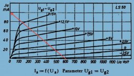
I'm trying to find a working LTSpice model for the GU-50 (LS-50) in right handed triode mode (G1+G2 together). I have done a lot of googling, but to no avail. I have seen curves, but could not find any model.
I tried to use the pentode model, connecting G1 and G2 together, but I end up having to use +300V bias to get some meaningful anode current, which obviously does not match the curves.
Any help would be appreciated.
Regards,
Jose
There is GU-50 in “right-handed mode” here:
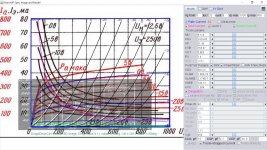
https://www.bartola.co.uk/valves/tag/gu50-right-handed-mode/I suppose you can plot it with DC sweep if you have GU50 model by connecting g2 and g1 as a variable input.
https://www.bartola.co.uk/valves/tag/gu50-right-handed-mode/I suppose you can plot it with DC sweep if you have GU50 model by connecting g2 and g1 as a variable input.
I was following those curves, yes. I realised I was using the wrong symbol for the GU50 model I used. Now I get something closer to what I expected, but the anode current is way higher than on Bartola's curvesThere is GU-50 in “right-handed mode” here:
https://www.bartola.co.uk/valves/tag/gu50-right-handed-mode/I suppose you can plot it with DC sweep if you have GU50 model by connecting g2 and g1 as a variable input.
GU50 model is found here: https://www.diyaudio.com/community/threads/g2-using-mosfet-ultralinear-feed.356896/page-2
Attachments
That model gives the right results, many thanks for that!GU50 model is found here: https://www.diyaudio.com/community/threads/g2-using-mosfet-ultralinear-feed.356896/page-2
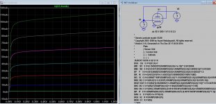
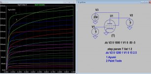
GU50 Paint Tools model:
Code:
**** GU50 ******************************************
* Created on 02/12/2022 12:08 using paint_kip.jar
* www.dmitrynizh.com/tubeparams_image.htm
* Plate Curves image file: GU50.jpg
* Data source link: <plate curves URL>
*----------------------------------------------------------------------------------
.SUBCKT GU50 P G2 G K ; LTSpice tetrode.asy pinout
* .SUBCKT GU50 P G K G2 ; Koren Pentode Pspice pinout
+ PARAMS: MU=6.118 KG1=1424.85 KP=21.49 KVB=156.67 VCT=3.865 EX=1.4 KG2=6813.5 KNEE=246.13 KVC=1.584
+ KLAM=1.86E-10 KLAMG=2.174E-7 KNEE2=29.48 KNEX=268.19  KNK=-0.5511 KNG=0.01128 KNPL=3.5 KNSL=12.07 KNPR=80.35 KNSR=38.46
+ CCG=15P CGP=0.1P CCP=10.3P VGOFF=-1.287 IGA=0.00122 IGB=0.3 IGC=8 IGEX=2
* Vp_MAX=1000 Ip_MAX=800 Vg_step=20 Vg_start=0 Vg_count=8
* X_MIN=149 Y_MIN=65 X_SIZE=666 Y_SIZE=522 FSZ_X=1296 FSZ_Y=736 XYGrid=false
* Rp=1400 Vg_ac=20 P_max=40 Vg_qui=-70 Vp_qui=300
* showLoadLine=n showIp=y isDHP=n isPP=n isAsymPP=n isUL=n showDissipLimit=y
* showIg1=y isInputSnapped=y addLocalNFB=n
* XYProjections=n harmonicPlot=y dissipPlot=n
* UL=0.43 EG2=250 gridLevel2=y addKink=y isTanhKnee=y advSigmoid=n
*----------------------------------------------------------------------------------
RE1  7 0  1G    ; DUMMY SO NODE 7 HAS 2 CONNECTIONS
E1   7 0  VALUE=  ; E1 BREAKS UP LONG EQUATION FOR G1.
+{V(G2,K)/KP*LOG(1+EXP((1/MU+(VCT+V(G,K))/SQRT(KVB+V(G2,K)*V(G2,K)))*KP))}
RE2  6 0  1G    ; DUMMY SO NODE 6 HAS 2 CONNECTIONS
E2  6 0  VALUE={(PWR(V(7),EX)+PWRS(V(7),EX))} ; Kg1 times KIT current
RE21 21 0 1
E21  21 0 VALUE={V(6)/KG1*ATAN((V(P,K)+KNEX)/KNEE)*TANH(V(P,K)/KNEE2)} ; Ip with knee but no slope and no kink
RE22 22 0 1 ; E22: kink curr deviation for plate
E22  22 0 VALUE={V(21)*LIMIT(KNK-V(G,K)*KNG,0,0.3)*(-ATAN((V(P,K)-KNPL)/KNSL)+ATAN((V(P,K)-KNPR)/KNSR))}
G1   P  K  VALUE={V(21)*(1+KLAMG*V(P,K))+KLAM*V(P,K) + V(22)}
* Alexander Gurskii screen current, see audioXpress 2/2011, with slope and kink added
RE43 43 K 1G ; Dummy
E43  43 G2 VALUE={0} ; Dummy
G2   43 K  VALUE={V(6)/KG2*(KVC-ATAN((V(P,K)+KNEX)/KNEE)*TANH(V(P,K)/KNEE2))/(1+KLAMG*V(P,K))-V(22)}
RCP  P K  1G     ; FOR CONVERGENCE
C1   K G  {CCG}  ; CATHODE-GRID 1
C2   G P  {CGP}  ; GRID 1-PLATE
C3   K P  {CCP}  ; CATHODE-PLATE
RE23 G 0 1G
GG G K VALUE={(IGA+IGB/(IGC+V(P,K)))*(MU/KG1)*
+(PWR(V(G,K)-VGOFF,IGEX)+PWRS(V(G,K)-VGOFF,IGEX))}
.ENDS
*$
Attachments
What's the difference with the previous one from your link? Just the layout?GU50 Paint Tools model:
Code:**** GU50 ****************************************** * Created on 02/12/2022 12:08 using paint_kip.jar * www.dmitrynizh.com/tubeparams_image.htm * Plate Curves image file: GU50.jpg * Data source link: <plate curves URL> *---------------------------------------------------------------------------------- .SUBCKT GU50 P G2 G K ; LTSpice tetrode.asy pinout * .SUBCKT GU50 P G K G2 ; Koren Pentode Pspice pinout + PARAMS: MU=6.118 KG1=1424.85 KP=21.49 KVB=156.67 VCT=3.865 EX=1.4 KG2=6813.5 KNEE=246.13 KVC=1.584 + KLAM=1.86E-10 KLAMG=2.174E-7 KNEE2=29.48 KNEX=268.19 KNK=-0.5511 KNG=0.01128 KNPL=3.5 KNSL=12.07 KNPR=80.35 KNSR=38.46 + CCG=15P CGP=0.1P CCP=10.3P VGOFF=-1.287 IGA=0.00122 IGB=0.3 IGC=8 IGEX=2 * Vp_MAX=1000 Ip_MAX=800 Vg_step=20 Vg_start=0 Vg_count=8 * X_MIN=149 Y_MIN=65 X_SIZE=666 Y_SIZE=522 FSZ_X=1296 FSZ_Y=736 XYGrid=false * Rp=1400 Vg_ac=20 P_max=40 Vg_qui=-70 Vp_qui=300 * showLoadLine=n showIp=y isDHP=n isPP=n isAsymPP=n isUL=n showDissipLimit=y * showIg1=y isInputSnapped=y addLocalNFB=n * XYProjections=n harmonicPlot=y dissipPlot=n * UL=0.43 EG2=250 gridLevel2=y addKink=y isTanhKnee=y advSigmoid=n *---------------------------------------------------------------------------------- RE1 7 0 1G ; DUMMY SO NODE 7 HAS 2 CONNECTIONS E1 7 0 VALUE= ; E1 BREAKS UP LONG EQUATION FOR G1. +{V(G2,K)/KP*LOG(1+EXP((1/MU+(VCT+V(G,K))/SQRT(KVB+V(G2,K)*V(G2,K)))*KP))} RE2 6 0 1G ; DUMMY SO NODE 6 HAS 2 CONNECTIONS E2 6 0 VALUE={(PWR(V(7),EX)+PWRS(V(7),EX))} ; Kg1 times KIT current RE21 21 0 1 E21 21 0 VALUE={V(6)/KG1*ATAN((V(P,K)+KNEX)/KNEE)*TANH(V(P,K)/KNEE2)} ; Ip with knee but no slope and no kink RE22 22 0 1 ; E22: kink curr deviation for plate E22 22 0 VALUE={V(21)*LIMIT(KNK-V(G,K)*KNG,0,0.3)*(-ATAN((V(P,K)-KNPL)/KNSL)+ATAN((V(P,K)-KNPR)/KNSR))} G1 P K VALUE={V(21)*(1+KLAMG*V(P,K))+KLAM*V(P,K) + V(22)} * Alexander Gurskii screen current, see audioXpress 2/2011, with slope and kink added RE43 43 K 1G ; Dummy E43 43 G2 VALUE={0} ; Dummy G2 43 K VALUE={V(6)/KG2*(KVC-ATAN((V(P,K)+KNEX)/KNEE)*TANH(V(P,K)/KNEE2))/(1+KLAMG*V(P,K))-V(22)} RCP P K 1G ; FOR CONVERGENCE C1 K G {CCG} ; CATHODE-GRID 1 C2 G P {CGP} ; GRID 1-PLATE C3 K P {CCP} ; CATHODE-PLATE RE23 G 0 1G GG G K VALUE={(IGA+IGB/(IGC+V(P,K)))*(MU/KG1)* +(PWR(V(G,K)-VGOFF,IGEX)+PWRS(V(G,K)-VGOFF,IGEX))} .ENDS *$
I found lillte information of which curve it's based on. As you can see (typical of Ayumi pentode model) it does not follow the original curve very well at left knee section I think that is enough to cause some differences (Thd distortion, power output etc..).
Attachments
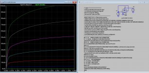
Many, many thanks. Regards ThereseTry this PC88 model:
Code:* Plate Curves image file: pc88.jpg * Data source link: *---------------------------------------------------------------------------------- .SUBCKT PC88 1 2 3 ; Plate Grid Cathode + PARAMS: CCG=3.8P CGP=1.2P CCP=0.055P + MU=71.72 KG1=232.05 KP=438.5 KVB=466.33 VCT=0.3582 EX=1.365 + VGOFF=-0.6 IGA=2E-4 IGB=0.054 IGC=9.92 IGEX=1.64 * Vp_MAX=300 Ip_MAX=40 Vg_step=0.5 Vg_start=0 Vg_count=9 * Rp=4000 Vg_ac=55 P_max=2 Vg_qui=-48 Vp_qui=300 * X_MIN=28 Y_MIN=34 X_SIZE=805 Y_SIZE=538 FSZ_X=1296 FSZ_Y=736 XYGrid=false * showLoadLine=n showIp=y isDHT=n isPP=n isAsymPP=n showDissipLimit=y * showIg1=y gridLevel2=y isInputSnapped=n * XYProjections=n harmonicPlot=n dissipPlot=n *---------------------------------------------------------------------------------- E1 7 0 VALUE={V(1,3)/KP*LOG(1+EXP(KP*(1/MU+(VCT+V(2,3))/SQRT(KVB+V(1,3)*V(1,3)))))} RE1 7 0 1G ; TO AVOID FLOATING NODES G1 1 3 VALUE={(PWR(V(7),EX)+PWRS(V(7),EX))/KG1} RCP 1 3 1G ; TO AVOID FLOATING NODES C1 2 3 {CCG} ; CATHODE-GRID C2 2 1 {CGP} ; GRID=PLATE C3 1 3 {CCP} ; CATHODE-PLATE RE2 2 0 1G EGC 8 0 VALUE={V(2,3)-VGOFF} ; POSITIVE GRID THRESHOLD GG 2 3 VALUE={(IGA+IGB/(IGC+V(1,3)))*(MU/KG1)*(PWR(V(8),IGEX)+PWRS(V(8),IGEX))} .ENDS *$
I'm very excited! My son fast tracked me to getting LT spice figured out enough to get going, so I'm on my way. There is one favor though, tube models are abundant here. But what do you all do for CCS's on plate or cathode? Do you just make the CCS from its discreet parts, I guess right? Then I suppose save those as subcircuits so to make them re-useable as 'CCS' symbols with the double rings or just a rectangle with two pins. The first circuit we tried happened to have a CCS symbol on it, I just changed it to a resistor. Lots of concepts I need to learn yet I guess.
If you are just trying to assess a circuit's performance with and without a CCS, then it's more practical to just start the simulation process using the built-in LTspice current source component. After you are satisfied with the answer, then you can construct a current source from discreet parts or ICs. That way, you aren't skewing the simulation results with a CCS circuit that might be causing a problem that isn't obvious.
It's usually wise to limit the number of variables that are in play at the same time until you know how each one affects the results.
It's usually wise to limit the number of variables that are in play at the same time until you know how each one affects the results.
Is there a secret to getting the pentodes to function in LT spice? I used the generic pentode from the library, and assigned the 6u8p model to it, just like I’ve done previously with triodes. I’m getting a messageWay back in 2013, user jazbo8 assembled the Ayumi tube models into a single ZIP file. You can find the LTspice version of that library (updated by kevinkr on June 29, 2018) in the following link.
https://www.diyaudio.com/community/threads/vacuum-tube-spice-models.243950/post-3662623
”port(pin) count mismatch between the definition of sub circuit “6u8p” and instance: “xu3”
the instance has more connections than the definition. Perhaps there is no screen defined here, and I need to use the gerodet version?
Most "pentode" SPICE models are actually tetrode models; very few model the pentode's suppressor grid because it is generally assumed to be connected to the cathode, rather than being used as a modulating element. So you should use the LTspice built-in tetrode symbol instead, ignoring the suppressor grid in your LTspice schematic. This should work.
Last edited:
Thanks. Yes, models are not perfect. There are some that match reality quite well. Is a hit and miss.I found lillte information of which curve it's based on. As you can see (typical of Ayumi pentode model) it does not follow the original curve very well at left knee section I think that is enough to cause some differences (Thd distortion, power output etc..).
- Home
- Amplifiers
- Tubes / Valves
- Vacuum Tube SPICE Models