E81L model:
Code:
**** E81L ******************************************
* Created on 11/09/2021 02:02 using paint_kip.jar
* [url=http://www.dmitrynizh.com/tubeparams_image.htm]Model Paint Tools: Trace Tube Parameters over Plate Curves, Interactively[/url]
* Plate Curves image file: e81l.png
* Data source link: <plate curves URL>
*----------------------------------------------------------------------------------
.SUBCKT E81L P G2 G K ; LTSpice tetrode.asy pinout
* .SUBCKT E81L P G K G2 ; Koren Pentode Pspice pinout
+ PARAMS: MU=36 KG1=3018.36 KP=143.85 KVB=63.7 VCT=0.911 EX=2.145 KG2=8098.77 KNEE=3.2 KVC=1.834
+ KLAM=1.25E-8 KLAMG=2.992E-4 KNEE2=19.08 KNEX=9.04  KNK=5.126E-4 KNG=1.501E-5
+ CCG=3P CGP=1.4P CCP=1.9P VGOFF=-0.6 IGA=0.001 IGB=0.3 IGC=8 IGEX=1.86
* Vp_MAX=350 Ip_MAX=50 Vg_step=1 Vg_start=0 Vg_count=9
* X_MIN=31 Y_MIN=39 X_SIZE=835 Y_SIZE=601 FSZ_X=1296 FSZ_Y=736 XYGrid=false
* Rp=1400 Vg_ac=20 P_max=4.5 Vg_qui=-4 Vp_qui=300
* showLoadLine=n showIp=y isDHP=n isPP=n isAsymPP=n isUL=n showDissipLimit=y
* showIg1=y isInputSnapped=y addLocalNFB=n
* XYProjections=n harmonicPlot=y dissipPlot=n
* UL=0.43 EG2=210 gridLevel2=y addKink=n isTanhKnee=y advSigmoid=n
*----------------------------------------------------------------------------------
RE1  7 0  1G    ; DUMMY SO NODE 7 HAS 2 CONNECTIONS
E1   7 0  VALUE=  ; E1 BREAKS UP LONG EQUATION FOR G1.
+{V(G2,K)/KP*LOG(1+EXP((1/MU+(VCT+V(G,K))/SQRT(KVB+V(G2,K)*V(G2,K)))*KP))}
RE2  6 0  1G    ; DUMMY SO NODE 6 HAS 2 CONNECTIONS
E2  6 0  VALUE={(PWR(V(7),EX)+PWRS(V(7),EX))} ; Kg1 times KIT current
G1   P K  VALUE={V(6)/KG1*ATAN((V(P,K)+KNEX)/KNEE)*TANH(V(P,K)/KNEE2)*(1+KLAMG*V(P,K))+KLAM*V(P,K)}
* Alexander Gurskii screen current, see audioXpress 2/2011
RE4K 4K K 1G ; Dummy, per Alex request
E4K 4K  4 VALUE={0} ; Dummy, per Alex request
G4K 4K K VALUE={V(6)/KG2*(KVC-ATAN((V(P,K)+KNEX)/KNEE)*TANH(V(P,K)/KNEE2))/(1+KLAMG*V(P,K))}
RCP  P K  1G     ; FOR CONVERGENCE
C1   K G  {CCG}  ; CATHODE-GRID 1
C2   G P  {CGP}  ; GRID 1-PLATE
C3   K P  {CCP}  ; CATHODE-PLATE
RE23 G 0 1G
GG G K VALUE={(IGA+IGB/(IGC+V(P,K)))*(MU/KG1)*
+(PWR(V(G,K)-VGOFF,IGEX)+PWRS(V(G,K)-VGOFF,IGEX))}
.ENDS
*$
Attachments
This update fixed missing Ig2, E81L:
Code:
**** E81L ******************************************
* Created on 11/09/2021 03:26 using paint_kip.jar
* [URL="http://www.dmitrynizh.com/tubeparams_image.htm"]www.dmitrynizh.com/tubeparams_image.htm[/URL]
* Plate Curves image file: e81l.png
* Data source link: <plate curves URL>
*----------------------------------------------------------------------------------
.SUBCKT E81L P G2 G K ; LTSpice tetrode.asy pinout
* .SUBCKT E81L P G K G2 ; Koren Pentode Pspice pinout
+ PARAMS: MU=36 KG1=3018.36 KP=143.85 KVB=63.7 VCT=0.911 EX=2.145 KG2=8098.77 KNEE=5.888 KVC=1.834
+ KLAM=1.25E-8 KLAMG=2.992E-4 KNEE2=13.22 KNEX=11.12  KNK=5.126E-4 KNG=1.501E-5 KNPL=50 KNSL=11 KNPR=120 KNSR=29
+ CCG=3P CGP=1.4P CCP=1.9P VGOFF=-0.6 IGA=0.001 IGB=0.3 IGC=8 IGEX=1.86
* Vp_MAX=350 Ip_MAX=50 Vg_step=1 Vg_start=0 Vg_count=9
* X_MIN=30 Y_MIN=19 X_SIZE=832 Y_SIZE=601 FSZ_X=1296 FSZ_Y=736 XYGrid=false
* Rp=1400 Vg_ac=20 P_max=4.5 Vg_qui=-4 Vp_qui=300
* showLoadLine=n showIp=y isDHP=n isPP=n isAsymPP=n isUL=n showDissipLimit=y
* showIg1=y isInputSnapped=y addLocalNFB=n
* XYProjections=n harmonicPlot=y dissipPlot=n
* UL=0.43 EG2=210 gridLevel2=y addKink=y isTanhKnee=y advSigmoid=n
*----------------------------------------------------------------------------------
RE1  7 0  1G    ; DUMMY SO NODE 7 HAS 2 CONNECTIONS
E1   7 0  VALUE=  ; E1 BREAKS UP LONG EQUATION FOR G1.
+{V(G2,K)/KP*LOG(1+EXP((1/MU+(VCT+V(G,K))/SQRT(KVB+V(G2,K)*V(G2,K)))*KP))}
RE2  6 0  1G    ; DUMMY SO NODE 6 HAS 2 CONNECTIONS
E2  6 0  VALUE={(PWR(V(7),EX)+PWRS(V(7),EX))} ; Kg1 times KIT current
RE21 21 0 1
E21  21 0 VALUE={V(6)/KG1*ATAN((V(P,K)+KNEX)/KNEE)*TANH(V(P,K)/KNEE2)} ; Ip with knee but no slope and no kink
RE22 22 0 1 ; E22: kink curr deviation for plate
E22  22 0 VALUE={V(21)*LIMIT(KNK-V(G,K)*KNG,0,0.3)*(-ATAN((V(P,K)-KNPL)/KNSL)+ATAN((V(P,K)-KNPR)/KNSR))}
G1   P  K  VALUE={V(21)*(1+KLAMG*V(P,K))+KLAM*V(P,K) + V(22)}
* Alexander Gurskii screen current, see audioXpress 2/2011, with slope and kink added
RE43 43 K 1G ; Dummy
E43  43 G2 VALUE={0} ; Dummy
G2   43 K  VALUE={V(6)/KG2*(KVC-ATAN((V(P,K)+KNEX)/KNEE)*TANH(V(P,K)/KNEE2))/(1+KLAMG*V(P,K))-V(22)}
RCP  P K  1G     ; FOR CONVERGENCE
C1   K G  {CCG}  ; CATHODE-GRID 1
C2   G P  {CGP}  ; GRID 1-PLATE
C3   K P  {CCP}  ; CATHODE-PLATE
RE23 G 0 1G
GG G K VALUE={(IGA+IGB/(IGC+V(P,K)))*(MU/KG1)*
+(PWR(V(G,K)-VGOFF,IGEX)+PWRS(V(G,K)-VGOFF,IGEX))}
.ENDS
*$E81L grid 2 current
Hi Koonw,
Thanks for the quick work on the model. I also tried Paint_KIP and could not figure out how to fix the model errors.
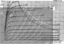
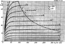
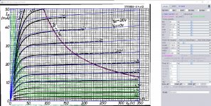
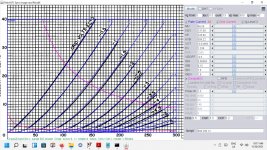
Can you check the G2 current data of your model? The Philips data sheet indicated G2 current of 5.3 mA at 210V plate, 20 mA plate current, and -2V bias. The chart on page 6 of 1968 data sheet showed the similar amount. So I would expect the 3rd (grid current) green line from top down should be around 5 mA.
If you agree, can you revise the model again? Appreciate your help.
Hi Koonw,
Thanks for the quick work on the model. I also tried Paint_KIP and could not figure out how to fix the model errors.
Can you check the G2 current data of your model? The Philips data sheet indicated G2 current of 5.3 mA at 210V plate, 20 mA plate current, and -2V bias. The chart on page 6 of 1968 data sheet showed the similar amount. So I would expect the 3rd (grid current) green line from top down should be around 5 mA.
If you agree, can you revise the model again? Appreciate your help.
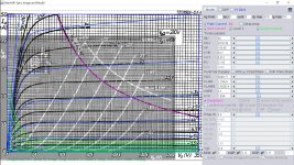
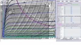
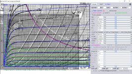
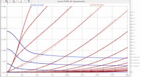
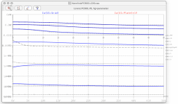
Here is Ig2 plot of the updated model (posted previously), nothing has been changed, just plot Ig2. Adjust params Kg2 and KVC will change Ig2 curve, params Screen current and Kink needs to be on, but the Kink is unchecked in the earliest model (think that is a bug) now included. Should you need to correct the model, you need the original curve, once in Paint, click on the Model, paste the model code and then Update. Adjust the X,Y ordinates to make sure it matches the original scale Ia/Va curve. As there is no Screen Current curve, you need to alter it if it's incorrect. I must have mistaken 0v instead of -2V, anyway the triode curve now lined much better. Thank you very much together we made better model.
Attachments
Last edited:
E81L model with Ig2 adjusted: ( also alter inter-electode capacitance yourself)
Code:
**** E81L ******************************************
 * Created on 11/09/2021 10:59 using paint_kip.jar
* [URL="http://www.dmitrynizh.com/tubeparams_image.htm"]Model Paint Tools: Trace Tube Parameters over Plate Curves, Interactively[/URL]
* Plate Curves image file: e81l.png
* Data source link: <plate curves URL>
*----------------------------------------------------------------------------------
.SUBCKT E81L P G2 G K ; LTSpice tetrode.asy pinout
* .SUBCKT E81L P G K G2 ; Koren Pentode Pspice pinout
+ PARAMS: MU=36 KG1=3018.36 KP=143.85 KVB=63.7 VCT=0.911 EX=2.145 KG2=8098.77 KNEE=5.888 KVC=2.384
+ KLAM=1.25E-8 KLAMG=2.992E-4 KNEE2=13.22 KNEX=11.12  KNK=5.126E-4 KNG=1.501E-5 KNPL=50 KNSL=11 KNPR=120 KNSR=29
+ CCG=3P CGP=1.4P CCP=1.9P VGOFF=-0.6 IGA=0.001 IGB=0.3 IGC=8 IGEX=1.86
* Vp_MAX=350 Ip_MAX=50 Vg_step=1 Vg_start=0 Vg_count=9
* X_MIN=37 Y_MIN=18 X_SIZE=832 Y_SIZE=606 FSZ_X=1296 FSZ_Y=736 XYGrid=false
* Rp=1400 Vg_ac=20 P_max=4.5 Vg_qui=-4 Vp_qui=300
* showLoadLine=n showIp=y isDHP=n isPP=n isAsymPP=n isUL=n showDissipLimit=y
* showIg1=y isInputSnapped=y addLocalNFB=n
* XYProjections=n harmonicPlot=y dissipPlot=n
* UL=0.43 EG2=210 gridLevel2=y addKink=y isTanhKnee=y advSigmoid=n
*----------------------------------------------------------------------------------
RE1  7 0  1G    ; DUMMY SO NODE 7 HAS 2 CONNECTIONS
E1   7 0  VALUE=  ; E1 BREAKS UP LONG EQUATION FOR G1.
+{V(G2,K)/KP*LOG(1+EXP((1/MU+(VCT+V(G,K))/SQRT(KVB+V(G2,K)*V(G2,K)))*KP))}
RE2  6 0  1G    ; DUMMY SO NODE 6 HAS 2 CONNECTIONS
E2  6 0  VALUE={(PWR(V(7),EX)+PWRS(V(7),EX))} ; Kg1 times KIT current
RE21 21 0 1
E21  21 0 VALUE={V(6)/KG1*ATAN((V(P,K)+KNEX)/KNEE)*TANH(V(P,K)/KNEE2)} ; Ip with knee but no slope and no kink
RE22 22 0 1 ; E22: kink curr deviation for plate
E22  22 0 VALUE={V(21)*LIMIT(KNK-V(G,K)*KNG,0,0.3)*(-ATAN((V(P,K)-KNPL)/KNSL)+ATAN((V(P,K)-KNPR)/KNSR))}
G1   P  K  VALUE={V(21)*(1+KLAMG*V(P,K))+KLAM*V(P,K) + V(22)}
* Alexander Gurskii screen current, see audioXpress 2/2011, with slope and kink added
RE43 43 K 1G ; Dummy
E43  43 G2 VALUE={0} ; Dummy
G2   43 K  VALUE={V(6)/KG2*(KVC-ATAN((V(P,K)+KNEX)/KNEE)*TANH(V(P,K)/KNEE2))/(1+KLAMG*V(P,K))-V(22)}
RCP  P K  1G     ; FOR CONVERGENCE
C1   K G  {CCG}  ; CATHODE-GRID 1
C2   G P  {CGP}  ; GRID 1-PLATE
C3   K P  {CCP}  ; CATHODE-PLATE
RE23 G 0 1G
GG G K VALUE={(IGA+IGB/(IGC+V(P,K)))*(MU/KG1)*
+(PWR(V(G,K)-VGOFF,IGEX)+PWRS(V(G,K)-VGOFF,IGEX))}
.ENDS
*$
Attachments
Last edited:
Refined model, triode curve better matched the original.
Code:
**** E81L ******************************************
* Created on 11/09/2021 11:30 using paint_kip.jar
* [URL="http://www.dmitrynizh.com/tubeparams_image.htm"]Model Paint Tools: Trace Tube Parameters over Plate Curves, Interactively[/URL]
* Plate Curves image file: e81l.png
* Data source link: <plate curves URL>
*----------------------------------------------------------------------------------
.SUBCKT E81L P G2 G K ; LTSpice tetrode.asy pinout
* .SUBCKT E81L P G K G2 ; Koren Pentode Pspice pinout
+ PARAMS: MU=36 KG1=1780.83 KP=247.42 KVB=308.31 VCT=0.7561 EX=1.866 KG2=4616.3 KNEE=0.0368 KVC=2.504
+ KLAM=1.25E-8 KLAMG=2.992E-4 KNEE2=22.16 KNEX=0.93  KNK=1.435E-4 KNG=1.411E-5 KNPL=37 KNSL=11 KNPR=120 KNSR=29
+ CCG=3P CGP=1.4P CCP=1.9P VGOFF=-0.6 IGA=0.001 IGB=0.3 IGC=8 IGEX=1.86
* Vp_MAX=350 Ip_MAX=50 Vg_step=1 Vg_start=0 Vg_count=9
* X_MIN=37 Y_MIN=18 X_SIZE=832 Y_SIZE=606 FSZ_X=1296 FSZ_Y=736 XYGrid=false
* Rp=1400 Vg_ac=20 P_max=4.5 Vg_qui=-4 Vp_qui=300
* showLoadLine=n showIp=y isDHP=n isPP=n isAsymPP=n isUL=n showDissipLimit=y
* showIg1=y isInputSnapped=y addLocalNFB=n
* XYProjections=n harmonicPlot=y dissipPlot=n
* UL=0.43 EG2=210 gridLevel2=y addKink=y isTanhKnee=y advSigmoid=n
*----------------------------------------------------------------------------------
RE1  7 0  1G    ; DUMMY SO NODE 7 HAS 2 CONNECTIONS
E1   7 0  VALUE=  ; E1 BREAKS UP LONG EQUATION FOR G1.
+{V(G2,K)/KP*LOG(1+EXP((1/MU+(VCT+V(G,K))/SQRT(KVB+V(G2,K)*V(G2,K)))*KP))}
RE2  6 0  1G    ; DUMMY SO NODE 6 HAS 2 CONNECTIONS
E2  6 0  VALUE={(PWR(V(7),EX)+PWRS(V(7),EX))} ; Kg1 times KIT current
RE21 21 0 1
E21  21 0 VALUE={V(6)/KG1*ATAN((V(P,K)+KNEX)/KNEE)*TANH(V(P,K)/KNEE2)} ; Ip with knee but no slope and no kink
RE22 22 0 1 ; E22: kink curr deviation for plate
E22  22 0 VALUE={V(21)*LIMIT(KNK-V(G,K)*KNG,0,0.3)*(-ATAN((V(P,K)-KNPL)/KNSL)+ATAN((V(P,K)-KNPR)/KNSR))}
G1   P  K  VALUE={V(21)*(1+KLAMG*V(P,K))+KLAM*V(P,K) + V(22)}
* Alexander Gurskii screen current, see audioXpress 2/2011, with slope and kink added
RE43 43 K 1G ; Dummy
E43  43 G2 VALUE={0} ; Dummy
G2   43 K  VALUE={V(6)/KG2*(KVC-ATAN((V(P,K)+KNEX)/KNEE)*TANH(V(P,K)/KNEE2))/(1+KLAMG*V(P,K))-V(22)}
RCP  P K  1G     ; FOR CONVERGENCE
C1   K G  {CCG}  ; CATHODE-GRID 1
C2   G P  {CGP}  ; GRID 1-PLATE
C3   K P  {CCP}  ; CATHODE-PLATE
RE23 G 0 1G
GG G K VALUE={(IGA+IGB/(IGC+V(P,K)))*(MU/KG1)*
+(PWR(V(G,K)-VGOFF,IGEX)+PWRS(V(G,K)-VGOFF,IGEX))}
.ENDS
*$
Attachments
Last edited:
Hi Koonw,
I managed to revise the grid current. See attached. However, I could not output the same model as your second note. There were a few added lines and changes in that model. If you have a new Paint_KIP.jar program, can you please share with me.
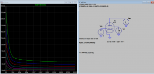
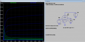
When I modified the model and plotted on LTspice, I found the model I modified did not show a high grid current at low plate voltage. However, it is not that critical for my simulation.
Below is my model modified according to your second note:
**** E81L ******************************************
* Created on 11/08/2021 20:53 using paint_kip.jar
* Model Paint Tools: Trace Tube Parameters over Plate Curves, Interactively
* Plate Curves image file: E81LPA.gif
* Data source link: <plate curves URL>
*----------------------------------------------------------------------------------
.SUBCKT E81L P G2 G K ; LTSpice tetrode.asy pinout
* .SUBCKT E81L P G K G2 ; Koren Pentode Pspice pinout
+ PARAMS: MU=36 KG1=3018.36 KP=143.85 KVB=63.7 VCT=0.911 EX=2.145 KG2=2753.58 KNEE=3.2 KVC=1.834
+ KLAM=1.25E-8 KLAMG=2.992E-4 KNEE2=20 KNEX=30 KNK=-0.044 KNG=0.006
+ CCG=3P CGP=1.4P CCP=1.9P VGOFF=-0.6 IGA=0.001 IGB=0.3 IGC=8 IGEX=2
* Vp_MAX=350 Ip_MAX=50 Vg_step=0.5 Vg_start=0 Vg_count=9
* X_MIN=80 Y_MIN=38 X_SIZE=1030 Y_SIZE=741 FSZ_X=1700 FSZ_Y=862 XYGrid=false
* Rp=1400 Vg_ac=20 P_max=4.5 Vg_qui=-2 Vp_qui=300
* showLoadLine=n showIp=y isDHP=n isPP=n isAsymPP=n isUL=n showDissipLimit=y
* showIg1=y isInputSnapped=y addLocalNFB=n
* XYProjections=n harmonicPlot=y dissipPlot=n
* UL=0.43 EG2=210 gridLevel2=y addKink=n isTanhKnee=y advSigmoid=n
*----------------------------------------------------------------------------------
RE1 7 0 1G ; DUMMY SO NODE 7 HAS 2 CONNECTIONS
E1 7 0 VALUE= ; E1 BREAKS UP LONG EQUATION FOR G1.
+{V(G2,K)/KP*LOG(1+EXP((1/MU+(VCT+V(G,K))/SQRT(KVB+V(G2,K)*V(G2,K)))*KP))}
RE2 6 0 1G ; DUMMY SO NODE 6 HAS 2 CONNECTIONS
E2 6 0 VALUE={(PWR(V(7),EX)+PWRS(V(7),EX))} ; Kg1 times KIT current
RE21 21 0 1
E21 21 0 VALUE={V(6)/KG1*ATAN((V(P,K)+KNEX)/KNEE)*TANH(V(P,K)/KNEE2)} ; Ip with knee but no slope and no kink
RE22 22 0 1 ; E22: kink curr deviation for plate
E22 22 0 VALUE={V(21)*LIMIT(KNK-V(G,K)*KNG,0,0.3)*(-ATAN((V(P,K)-KNPL)/KNSL)+ATAN((V(P,K)-KNPR)/KNSR))}
G1 P K VALUE={V(21)*(1+KLAMG*V(P,K))+KLAM*V(P,K) + V(22)}
* Alexander Gurskii screen current, see audioXpress 2/2011
RE43 43 K 1G ; Dummy, per Alex request
E43 43 G2 VALUE={0} ; Dummy, per Alex request
G2 43 K VALUE={V(6)/KG2*(KVC-ATAN((V(P,K)+KNEX)/KNEE)*TANH(V(P,K)/KNEE2))/(1+KLAMG*V(P,K))}
RCP P K 1G ; FOR CONVERGENCE
C1 K G {CCG} ; CATHODE-GRID 1
C2 G P {CGP} ; GRID 1-PLATE
C3 K P {CCP} ; CATHODE-PLATE
RE23 G 0 1G
GG G K VALUE={(IGA+IGB/(IGC+V(P,K)))*(MU/KG1)*
+(PWR(V(G,K)-VGOFF,IGEX)+PWRS(V(G,K)-VGOFF,IGEX))}
.ENDS
*$
I managed to revise the grid current. See attached. However, I could not output the same model as your second note. There were a few added lines and changes in that model. If you have a new Paint_KIP.jar program, can you please share with me.
When I modified the model and plotted on LTspice, I found the model I modified did not show a high grid current at low plate voltage. However, it is not that critical for my simulation.
Below is my model modified according to your second note:
**** E81L ******************************************
* Created on 11/08/2021 20:53 using paint_kip.jar
* Model Paint Tools: Trace Tube Parameters over Plate Curves, Interactively
* Plate Curves image file: E81LPA.gif
* Data source link: <plate curves URL>
*----------------------------------------------------------------------------------
.SUBCKT E81L P G2 G K ; LTSpice tetrode.asy pinout
* .SUBCKT E81L P G K G2 ; Koren Pentode Pspice pinout
+ PARAMS: MU=36 KG1=3018.36 KP=143.85 KVB=63.7 VCT=0.911 EX=2.145 KG2=2753.58 KNEE=3.2 KVC=1.834
+ KLAM=1.25E-8 KLAMG=2.992E-4 KNEE2=20 KNEX=30 KNK=-0.044 KNG=0.006
+ CCG=3P CGP=1.4P CCP=1.9P VGOFF=-0.6 IGA=0.001 IGB=0.3 IGC=8 IGEX=2
* Vp_MAX=350 Ip_MAX=50 Vg_step=0.5 Vg_start=0 Vg_count=9
* X_MIN=80 Y_MIN=38 X_SIZE=1030 Y_SIZE=741 FSZ_X=1700 FSZ_Y=862 XYGrid=false
* Rp=1400 Vg_ac=20 P_max=4.5 Vg_qui=-2 Vp_qui=300
* showLoadLine=n showIp=y isDHP=n isPP=n isAsymPP=n isUL=n showDissipLimit=y
* showIg1=y isInputSnapped=y addLocalNFB=n
* XYProjections=n harmonicPlot=y dissipPlot=n
* UL=0.43 EG2=210 gridLevel2=y addKink=n isTanhKnee=y advSigmoid=n
*----------------------------------------------------------------------------------
RE1 7 0 1G ; DUMMY SO NODE 7 HAS 2 CONNECTIONS
E1 7 0 VALUE= ; E1 BREAKS UP LONG EQUATION FOR G1.
+{V(G2,K)/KP*LOG(1+EXP((1/MU+(VCT+V(G,K))/SQRT(KVB+V(G2,K)*V(G2,K)))*KP))}
RE2 6 0 1G ; DUMMY SO NODE 6 HAS 2 CONNECTIONS
E2 6 0 VALUE={(PWR(V(7),EX)+PWRS(V(7),EX))} ; Kg1 times KIT current
RE21 21 0 1
E21 21 0 VALUE={V(6)/KG1*ATAN((V(P,K)+KNEX)/KNEE)*TANH(V(P,K)/KNEE2)} ; Ip with knee but no slope and no kink
RE22 22 0 1 ; E22: kink curr deviation for plate
E22 22 0 VALUE={V(21)*LIMIT(KNK-V(G,K)*KNG,0,0.3)*(-ATAN((V(P,K)-KNPL)/KNSL)+ATAN((V(P,K)-KNPR)/KNSR))}
G1 P K VALUE={V(21)*(1+KLAMG*V(P,K))+KLAM*V(P,K) + V(22)}
* Alexander Gurskii screen current, see audioXpress 2/2011
RE43 43 K 1G ; Dummy, per Alex request
E43 43 G2 VALUE={0} ; Dummy, per Alex request
G2 43 K VALUE={V(6)/KG2*(KVC-ATAN((V(P,K)+KNEX)/KNEE)*TANH(V(P,K)/KNEE2))/(1+KLAMG*V(P,K))}
RCP P K 1G ; FOR CONVERGENCE
C1 K G {CCG} ; CATHODE-GRID 1
C2 G P {CGP} ; GRID 1-PLATE
C3 K P {CCP} ; CATHODE-PLATE
RE23 G 0 1G
GG G K VALUE={(IGA+IGB/(IGC+V(P,K)))*(MU/KG1)*
+(PWR(V(G,K)-VGOFF,IGEX)+PWRS(V(G,K)-VGOFF,IGEX))}
.ENDS
*$
Attachments
I just wanted to send out a big thanks to all who've contributed their time and energy to building a fantastic library of tube models for LTspice here.
A friend wanted a design for a phono preamp using a hybrid FET-triode cascode first stage. I worked a bit in LTspice to come up with a proposed circuit, using models contributed by Adrian, Koonw, cogsngogs, Ayumi N., jackinnj (I'm sorry if I left anyone out). After building it, the real world device behaves almost exactly as predicted! The frequency response of the real preamp, as measured, is almost identical to the simulation's prediction. The only real difference is that the real world device has a very slight droop at high frequencies above 15kHz (very slight) while the simulation predicts no roll off at all until upwards of 40kHz. Real world stray capacitance is probably the cause of that. So, chalk one up for SPICE.
Thank you!
You are welcome, rongon!
Fine, that your friends hybrid amp worked as expected!
BTW, my new i5 model is getting now the "final polishing", and will be (if not something severe pops up) released soon. Main focus was to improve the convergence performance and also to get it accurate for remote cutoff triodes like the PC900, the ECC189 or the 6DS4.
BR Adrian
...as announced, here my first i5 triode model release!
The development took a lot of time, about a dozen beta versions, lot of testing...
Thanks to all involved testers:
rongon
Ray Waters
Achim
The i5 is probably the best tested triode spice model ever. Regarding convergence, I learnt that DC-coupled circuits are much more difficult. So I started to test my beta versions with a tube OpAmp circuit containing 10 triodes!
But the ultimate test circuit was a 1bit-ALU (Arithmetic-Logic-Unit) made with 39 (!!) triodes, challenging my beta versions a lot.
So, if a crazy guy wants to simulate a tube based number cruncher, this is possible now!
But back to the first i5 model:
It's the PC900/6HM5, a (semi) remote cutoff triode. For such triodes, the curves at higher Va voltages are special shaped. The i5 is the first model which is able to mimic such characteristics with a satisfying result.
All PC900/6HM5 electrode constructions seen so far were identical (although from different companies), so I assume that there is only 1 construction existing for that tube, and so I skipped the both manufacturer letters in the suffix - no need to distinguish between companies for this tube.
BR Adrian
Code:
*PC900 LTspice model based on the generic triode model from Adrian Immler, version i5
*A version log is at the end of this file
*100h BurnIn of 5 Lorenz tubes, sample selection and measurements done in Febr. 2021
*Params fitted to the measured values by Adrian Immler, Nov. 2021
*The high fit quality is presented at adrianimmler.simplesite.com
*History's best of tube decribing art (plus some new ideas) is merged to this new approach.
*@ neg. Vg, Ia accuracy is similar to Koren models, and unrivaled for remote cutoff triodes
*@ small neg. Vg, the "Anlauf" current is considered.
*@ pos. Vg, Ig and Ia accuracy is on a unrivaled level (including neg. Va range!)
*This offers new simulation possibilities like grid resistor bias, backward plate modulated stages,
*Audion radio circuits, low voltage amps, guitar distortion stages or pulsed stages.
*All PC900/6HM5 electrode designs found so far were identical => manufacturer not mentioned in the suffix
*                anode (plate)
*                | grid
*                | | cathode
*                | | |
.subckt PC900.i5 A G K
+ params:
*Parameters for space charge current Is (100% assigned to Ia @ Vg < 0)
+ mu   = 156   ;Determines the voltage gain @ constant Ia
+ rad  = 6k2   ;Differential anode resistance, set @ Iad and Vg=0V
+ Vct  = 0.288 ;Offsets the Ia-traces on the Va axis. Electrode material's contact potential
+ kp   = 270   ;Mimics the island effect
+ xs   = 1.5   ;Determines the curve of the Ia traces. Typically between 1.2 and 1.8
+ kIsr = 85m   ;Va-indepedent part of the Is reduction when gridcurrent occurs
+ kvdg  = 60   ;Va-depedent part of the Is reduction when gridcurrent occurs
*
*Parameters for assigning the space charge current to Ia and Ig @ Vg > 0
+ kB   = 0.16  ;Describes how fast Ia drops to zero when Va approaches zero.
+ radl = 780   ;Differential resistance for the Ia emission limit @ very small Va and Vg > 0
+ tsh  = 10    ;Ia transmission sharpness from 1th to 2nd Ia area. Keep between 3 and 20. Start with 20.
+ xl   = 1.5   ;Exponent for the emission limit
*
*Parameters of the grid-cathode vacuum diode
+ kg = 170     ;Inverse scaling factor for the Va independent part of Ig (caution - interacts with xg!)
+ Vctg = -0.55 ;Offsets the log Ig-traces on the Vg axis. Electrode material's contact potential
+ xg   = 1.1   ;Determines the curve of the Ig slope versus (positive) Vg and Va >> 0
+ VT   = 0.135 ;Log(Ig) slope @ Vg<0. VT=k/q*Tk (cathodes absolute temp, typically 1150K)
+ rTr  = 0.55  ;ratio of VT for Igr. Typically 0.8
+ kVT=0        ;Va dependant koeff. of VT
+ gft1 = 0.05  ;reduces the steering voltage around Vg=-Vg0, for finetuning purposes
+ gft1a= 0.3   ;reduces the steering voltage around Vg=-Vg=. Effect decreases with 1/(1+kB*Va)
+ gft2 = 0.2   ;finetunes the Igr drop @ incrasing Va and around Vg=-Vg0
*
*Parameters for the caps
+ cag  = 0p37  ;From datasheet
+ cak  = 0p08  ;From datasheet
+ cgk  = 3p3   ;From datasheet
*
*special purpose parameters
+ os = 1       ;Overall scaling factor, if a user wishes to simulate manufacturing tolerances
+ murc = 48    ;Mu of the remote cutoff triode
+ ksrc = 1k38  ;Inverse Iarc gain factor for the remote cuttoff triode
+ kprc = 106   ;Mimics the island effect for the remote cotoff triode
+ Vbatt = 0    ;heater battery voltage for direct heated battery triodes
+ Vdrmax = 100 ;max voltage of internal Vg drop, for convergence improvements
*
*Calculated parameters
+ Iad = {100/rad} ;Ia where the anode a.c. resistance is set according to rad.
+ ks = {pow(mu/(rad*xs*Iad**(1-1/xs)),-xs)} ;Reduces the unwished xs influence to the Ia slope
+ ksnom = {pow(mu/(rad*1.5*Iad**(1-1/1.5)),-1.5)} ;Sub-equation for calculating Vg0
+ Vg0 = {Vct + (Iad*ks)**(1/xs) - (Iad*ksnom)**(2/3)} ;Reduces the xs influence to Vct.
+ kl = {pow(1/(radl*xl*Ild**(1-1/xl)),-xl)} ;Reduces the xl influence to the Ia slope @ small Va
+ Ild = {sqrt(radl)*1m} ;Current where the Il a.c. resistance is set according to radl.
*
*Space charge current model
Rak A K 100G ;avoids "floating net" errors
Bft   ft 0 V=1/(1+pow(2*abs(v(G,Ki)+Vg0),3)) ;an auxiliary voltage to finetune the triode around Vg=-Vg0
Bggi GGi 0 V=(v(Gi,Ki)+Vg0)*(1/(1+kIsr*max(0, v(G,Ki)+Vg0))) - gft1*v(ft) - gft1a*v(ft)/(1+kB*v(Ahc)) ;Effective internal grid voltage.
Bahc Ahc 0 V=uramp(v(A,Ki)) ;Anode voltage, hard cut to zero @ neg. value
Bst   St 0 V=uramp(max(v(GGi)+v(A,Ki)/(mu), v(A,Ki)/kp*ln(1+exp(kp*(1/mu+v(GGi)/(1+v(Ahc)))))));Steering volt.
Bs    Ai Ki I=os/ks*pow(v(St),xs) ;Langmuir-Childs law for the space charge current Is
Bstrc Strc 0 V=uramp(max(v(GGi)+v(Ahc)/(murc), v(Ahc)/kprc*ln(1+exp(kprc*(1/murc+v(GGi)/(1+v(Ahc)))))));FOR REMOTE CUTOFF TUBES ONLY
Bsrc   Ai Ki I=os/ksrc*pow(v(Strc),xs) ;FOR REMOTE CUTOFF TUBES ONLY
*
*Anode current limit @ small Va
.func smin(z,y,k) {pow(pow(z+1f, -k)+pow(y+1f, -k), -1/k)} ;Min-function with smooth trans.
.func ssmin(z,y,k) {min(min(z,y), smin(z*1.003,y*1.003,k))};smin-function which suppresses small residual differencies
Ra  A Ai 1
Bgl Gi A I=uramp(i(Ra)-ssmin(1/kl*pow(v(Ahc),xl),i(Ra),tsh)) ;Ia emission limit
*
*Grid model
Rgk G K 10G ;avoids "floating net" errors
Bvdg G Gi I=1/kvdg*pow(v(G,Gi),1.5) ;Reduces the internal effective grid voltage when Ig rises
Bcoh G Gi I=pow(uramp(v(G,Gi)-Vdrmax),2) ;A convergence help which softly limits the internal Vg voltage drop.
Rgip G Gi 1G ;avoids some warnings
.func fVT() {VT*exp(-kVT*sqrt(v(A,Ki)))}
.func Ivd(Vvd, kvd, xvd, VTvd)  {if(Vvd < 3, 1/kvd*pow(VTvd*xvd*ln(1+exp(Vvd/VTvd/xvd)),xvd), 1/kvd*pow(Vvd, xvd))} ;Vacuum diode function
Bgvd G Ki I=Ivd(v(G,Ki) + Vctg + min(0,v(A,Ki)/mu), kg/os, xg, fVT()) ;limits the internal Vg for convergence reasons
Bstn Stn 0 V=v(GGi)+min(0,v(A,Ki))/mu ;special steering voltage, sensitive to negative Anodevoltages only
*Bgr Gi Ai I= ivd(v(Stn),ks/os, xs, rTr*fVT())/(1+(kB+v(ft)*gft2)*v(Ahc));Is reflection to grid when Va approaches zero
Bgr Gi Ai I=(ivd(v(Stn),ks/os, xs, rTr*fVT())+os/ksrc*pow(v(GGi),xs))/(1+(kB+v(ft)*gft2)*v(Ahc));FOR REMOTE CUTOFF TUBES ONLY
Bs0 Ai Ki  I=uramp(ivd(v(Stn),ks/os, xs, rTr*fVT()) - os/ks*pow(v(Stn),xs))
Bbatt Ki K V=Vbatt/2 ;for battery heated triodes; Offsets the average cathode potential to the half heater battery voltage
*
*Caps
C1 A G {cag}
C2 A K {cak}
C3 G K {cgk}
.ends
*
*Version log
*i1 :Initial version
*i2 :Pin order changed to the more common order A G K (Thanks to Markus Gyger for his tip)
*i3 :bugfix of the Ivd-function: now also usable for larger Vvd
*i4: Rgi replaced by a virtual vacuum diode (better convergence). ft1 deleted (no longer needed)
;2 new prarams for Ig finetuning @ Va and Vg near zero. New overall skaling factor os for aging etc.
*i5: improved convergence performance. PosVg/NegVa area now correct. Also accurate now for remote cutoff triodes!
Attachments
Last edited:
Thank you Adrian!!!
This is great. I will definitely be giving this new model a test drive, and soon.
I have an .asy worked up for a phono preamp with this class of RF triode as the input stage. I've collected a few models (including your recent PC97.i4), so I have something to compare this to.
Thank you for contributing so much of your time, energy, knowledge and skill to this project.
Oh, a question...
If I wanted to model stray capacitances, could I simply change the lines
*Parameters for the caps
+ cag = 0p37 ;From datasheet
+ cak = 0p08 ;From datasheet
+ cgk = 3p3 ;From datasheet
to this?
*Parameters for the caps
+ cag = 1p7 ;0p37 From datasheet plus 0p7 for strays
+ cak = 0p78 ;0p08 From datasheet plus 0p7 for strays
+ cgk = 4p0 ;3p3 From datasheet plus 0p7 for strays
That's adding 0.7pF to each internal interelectrode capacitance, in an attempt to account for typical in-circuit stray capacitances. Is that reasonable?
Last edited:
Hi Rongon
Thanks for your feedback.
Regarding the caps: Yes, you can simply change the lines as you proposed. Note that for cag, 0p37+0p7=1p07 instead of 1p7.
When it comes to the difficult issue of parasitic caps of a circuit, it may be also an approach to add a cap of x pF or so from each net to earth (or GND). Each cap may be adjusted considering the length of the assigned net, to come closer to reality.
BR Adrian
Did I make zhe correct 6J4WA model?
MODEL:
**** 6J4WA ******************************************
* Created on 11/29/2021 13:49 using paint_kit.jar 3.1
* Model Paint Tools: Trace Tube Parameters over Plate Curves, Interactively
* Plate Curves image file: 6J4WA.JPG
* Data source link:
*----------------------------------------------------------------------------------
.SUBCKT TRIODE_6J4WA 1 2 3 ; Plate Grid Cathode
+ PARAMS: CCG=3P CGP=1.4P CCP=1.9P RGI=2000
+ MU=7.568 KG1=1908.08 KP=20 KVB=0.01465 VCT=7.812E-5 EX=1.204
* Vp_MAX=300 Ip_MAX=40 Vg_step=15 Vg_start=0 Vg_count=5
* Rp=4000 Vg_ac=55 P_max=40 Vg_qui=-48 Vp_qui=300
* X_MIN=32 Y_MIN=52 X_SIZE=602 Y_SIZE=405 FSZ_X=1149 FSZ_Y=600 XYGrid=false
* showLoadLine=n showIp=y isDHT=n isPP=n isAsymPP=n showDissipLimit=y
* showIg1=n gridLevel2=n isInputSnapped=n
* XYProjections=n harmonicPlot=n dissipPlot=n
*----------------------------------------------------------------------------------
E1 7 0 VALUE={V(1,3)/KP*LOG(1+EXP(KP*(1/MU+(VCT+V(2,3))/SQRT(KVB+V(1,3)*V(1,3)))))}
RE1 7 0 1G ; TO AVOID FLOATING NODES
G1 1 3 VALUE={(PWR(V(7),EX)+PWRS(V(7),EX))/KG1}
RCP 1 3 1G ; TO AVOID FLOATING NODES
C1 2 3 {CCG} ; CATHODE-GRID
C2 2 1 {CGP} ; GRID=PLATE
C3 1 3 {CCP} ; CATHODE-PLATE
D3 5 3 DX ; POSITIVE GRID CURRENT
R1 2 5 {RGI} ; POSITIVE GRID CURRENT
.MODEL DX D(IS=1N RS=1 CJO=10PF TT=1N)
.ENDS
*$

No problem, 6j4wa model:
Code:
**** 6J4WA ** Advanced Grid Current **********************************
* Created on 11/30/2021 10:19 using paint_kit.jar 3.1
* [url=http://www.dmitrynizh.com/tubeparams_image.htm]Model Paint Tools: Trace Tube Parameters over Plate Curves, Interactively[/url]
* Plate Curves image file: 6j4wa.png
* Data source link:
*----------------------------------------------------------------------------------
.SUBCKT 6J4WA 1 2 3 ; Plate Grid Cathode
+ PARAMS: CCG=9.5P  CGP=3.3P CCP=0.2P
+ MU=69.26 KG1=137.09 KP=226.84 KVB=509.22 VCT=-0.03469 EX=1.234
+ VGOFF=-0.6 IGA=0.00093 IGB=0.15 IGC=7.6 IGEX=1.9
* Vp_MAX=300 Ip_MAX=40 Vg_step=0.5 Vg_start=0 Vg_count=13
* Rp=4000 Vg_ac=55 P_max=2.5 Vg_qui=-48 Vp_qui=300
* X_MIN=36 Y_MIN=70 X_SIZE=809 Y_SIZE=542 FSZ_X=1296 FSZ_Y=736 XYGrid=false
* showLoadLine=n showIp=y isDHT=n isPP=n isAsymPP=n showDissipLimit=y
* showIg1=y gridLevel2=y isInputSnapped=n
* XYProjections=n harmonicPlot=n dissipPlot=n
*----------------------------------------------------------------------------------
E1 7 0 VALUE={V(1,3)/KP*LOG(1+EXP(KP*(1/MU+(VCT+V(2,3))/SQRT(KVB+V(1,3)*V(1,3)))))}
RE1 7 0 1G  ; TO AVOID FLOATING NODES
G1 1 3 VALUE={(PWR(V(7),EX)+PWRS(V(7),EX))/KG1}
RCP 1 3 1G   ; TO AVOID FLOATING NODES
C1 2 3 {CCG} ; CATHODE-GRID
C2 2 1 {CGP} ; GRID=PLATE
C3 1 3 {CCP} ; CATHODE-PLATE
RE2 2 0 1G
EGC 8 0 VALUE={V(2,3)-VGOFF} ; POSITIVE GRID THRESHOLD
GG 2 3 VALUE={(IGA+IGB/(IGC+V(1,3)))*(MU/KG1)*(PWR(V(8),IGEX)+PWRS(V(8),IGEX))}
.ENDS
*$
Attachments
- Home
- Amplifiers
- Tubes / Valves
- Vacuum Tube SPICE Models