Morning lineup
My ECC86 model is on my website: http://adrianimmler.simplesite.com
However, for your purposes, the cogsncogs model will do it.
cheers, Adrian
My ECC86 model is on my website: http://adrianimmler.simplesite.com
However, for your purposes, the cogsncogs model will do it.
cheers, Adrian
THanks, Adrian
-------
Well I tried to download your ECC86 model.
But it is impossible to get .txt or .zip for download.
So, I have to settle for cogsncogs model.
In fact I didd learn german language in school.
But I have forgot most of it. I am 69 years old, soon 70.
-------
Well I tried to download your ECC86 model.
But it is impossible to get .txt or .zip for download.
So, I have to settle for cogsncogs model.
In fact I didd learn german language in school.
But I have forgot most of it. I am 69 years old, soon 70.
Last edited:
Hi lineup
Yes, unfortunately, simplesite doesn't provide convenient means for filesharing. So I do that with dropbox, but it is not a really good solution...
all the best, Adrian
PS: Here the code of my ECC86-i2 model:
Yes, unfortunately, simplesite doesn't provide convenient means for filesharing. So I do that with dropbox, but it is not a really good solution...
all the best, Adrian
PS: Here the code of my ECC86-i2 model:
Code:
*ECC86 LTspice model based on the generic triode model from Adrian Immler, version i2
*A version log is at the end of this file
*Params fitted to measured values of a Zaerix sample by Adrian Immler, Oct. 2018
*The high fit quality is presented at adrianimmler.simplesite.com
*History's best of tube decribing art (plus some new ideas) is merged to this new approach.
*@ neg. Vg, Ia accuracy is similar to Koren or Ayumi models.
*@ small neg. Vg, the "Anlauf" current is considered.
*@ pos. Vg, Ig and Ia accuracy is on a unrivaled level.
*This offers new simulation possibilities like bias point setting with MOhm grid resistor,
*Audion radio circuits, low voltage amps, guitar distortion stages or pulsed stages.
*                anode (plate)
*                | grid
*                | | cathode
*                | | |
.subckt ECC86_i2 A G K
.params
*Parameters for the space charge current @ Vg <= 0
+ mu   = 23 ;Determines the voltage gain @ constant Ia
+ rad  = 1180 ;Differential anode resistance, set @ Iad and Vg=0V
+ Vct  = 0.73 ;Offsets the Ia-traces on the Va axis. Electrode material's contact potential
+ kp   = 66 ;Mimics the island effect
+ xs   = 1.4 ;Determines the curve of the Ia traces. Typically between 1.2 and 1.8
*
*Parameters for assigning the space charge current to Ia and Ig @ Vg > 0
+ kB   = 3 ;Describes how fast Ia drops to zero when Va approaches zero.
+ radl = 425 ;Differential resistance for the Ia emission limit @ very small Va and Vg > 0
+ tsh  = 6 ;Ia transmission sharpness from 1th to 2nd Ia area. Keep between 3 and 20. Start with 20.
+ xl   = 1.4 ;Exponent for the emission limit
*
*Parameters of the grid-cathode vacuum diode
+ Rgi  = 135 ;Internal grid resistor. Causes an Ia reduction @ Ig > 0.
+ kg = 520 ;Inverse scaling factor for the Va independent part of Ig (caution - interacts with xg!)
+ Vctg = -0.23 ;Offsets the log Ig-traces on the Vg axis. Electrode material's contact potential
+ xg   = 1 ;Determines the curve of the Ig slope versus (positive) Vg and Va >> 0
+ VT   = 0.104 ;Log(Ig) slope @ Vg<0. VT=k/q*Tk (cathodes absolute temp, typically 1150K)
*
*Parameters for the caps
+ cag  = 1p3    ;From Philips datasheet. May lead to gain-decrease @ highest audible frequencies!
+ cak  = 1p8    ;From Philips datasheet
+ cgk  = 3p     ;From Philips datasheet
*
*Calculated parameters
+ Iad = 100/rad  ;Ia where the anode a.c. resistance is set according to rad.
+ ks = pow(mu/(rad*xs*Iad**(1-1/xs)),-xs) ;Reduces the unwished xs influence to the Ia slope
+ ksnom = pow(mu/(rad*1.5*Iad**(1-1/1.5)),-1.5) ;Sub-equation for calculating Vg0
+ Vg0 = Vct + (Iad*ks)**(1/xs) - (Iad*ksnom)**(2/3) ;Reduces the xs influence to Vct.
+ kl = pow(1/(radl*xl*Ild**(1-1/xl)),-xl) ;Reduces the xl influence to the Ia slope @ small Va
+ Ild = sqrt(radl)*1m ;Current where the Il a.c. resistance is set according to radl.
*
*Space charge current model
Bggi GGi 0 V=v(Gi,K)+Vg0 ;Effective internal grid voltage.
Bahc Ahc 0 V=uramp(v(A,K)) ;Anode voltage, hard cut to zero @ neg. values
Bst   St 0 V=max(v(GGi)+v(Ahc)/(mu), v(Ahc)/kp*ln(1+exp(kp*(1/mu+v(GGi)/(1+v(Ahc))))));Steering volt.
Bs    Ai K I=ft1()/ks*pow(v(St),xs) ;Langmuir-Childs law for the space charge current Is
.func ft1() {1+(1+tanh(4*v(GGi)))/20} ;Finetuning-function for better overall fit at pos Vg
*
*Anode current limit @ small Va
.func smin(x,y,k) {pow(pow(x+1f, -k)+pow(y+1f, -k), -1/k)} ;Min-function with smooth trans.
Ra  A Ai 1
Bgl Gi A I=min(i(Ra)-smin(1/kl*pow(v(Ahc),xl),i(Ra),tsh),i(Bgvd)*exp(4*v(G,K))) ;Ia emission limit
*
*Grid model
Rgi G Gi {Rgi} ;Internal grid resistor for "Ia-reduction" @ Vg > 0
.func Ivd(Vvd, kvd, xvd, VTvd)  {1/kvd*pow(VTvd*xvd*ln(1+exp(Vvd/VTvd/xvd)),xvd)} ;Vacuum diode function
Bgvd Gi K I=Ivd(v(G,K)+Vctg-1m*sqrt(v(Ahc)), kg, xg, VT) ;Grid-cathode vacuum diode
.func ft2() {7*(1-tanh(3*(v(G,K)+Vg0)))} ;Finetuning-func. improves ig-fit @ Vg near -0.5V, low Va.
Bgr Gi Ai I=ft1()*ivd(v(GGi),ks, xs, 0.8*VT)/(1+ft2()+kB*v(Ahc));Is reflection to grid when Va approaches zero
Bs0 Ai K  I=ft1()*ivd(v(GGi),ks, xs, 0.8*VT)/(1+ft2()) - ft1()/ks*pow(v(GGi),xs) ;Compensates neg Ia @ small Va and Vg near zero

*Caps
C1 A G {cag}
C2 A K {cak}
C3 G K {cgk}
.ends
*
*Version log
*i1 :Initial version
*i2 :Pin order changed to the more common order „A G K“ (Thanks to Markus Gyger for his tip)(...)
When I remember right, I still should have somewhere an ECC86 sample... I hope to find it, for a sim-versus-real-tube comparison.
Hi all
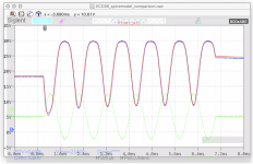
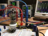
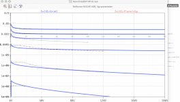
I finally found my ECC86 sample!
So I did exactly the same test setup as in spice (see #2895), and measured the anode voltage with the scope.
Red is simulation, Blue is measured.
It is up to you to build your own opinion about the ECC86_i2 model!

Happy Easter!
Adrian
Attachments
6BN11 model
*
* Generic pentode model: 6BN11_AN
* Copyright 2003--2008 by Ayumi Nakabayashi, All rights reserved.
* Version 3.10, Generated on Sat Nov 01 18:19:03 2014
* Plate
* | Screen Grid
* | | Control Grid
* | | | Cathode
* | | | |
.SUBCKT 6BN11 A G2 G1 K
BGG GG 0 V=V(G1,K)+0.80333486
BM1 M1 0 V=(0.016690499*(URAMP(V(G2,K))+1e-10))**-1.028498
BM2 M2 0 V=(0.59323756*(URAMP(V(GG)+URAMP(V(G2,K))/24.370897)))**2.528498
BP P 0 V=0.0032099434*(URAMP(V(GG)+URAMP(V(G2,K))/41.081176))**1.5
BIK IK 0 V=U(V(GG))*V(P)+(1-U(V(GG)))*0.0021774044*V(M1)*V(M2)
BIG IG 0 V=0.0016049717*URAMP(V(G1,K))**1.5*(URAMP(V(G1,K))/(URAMP(V(A,K))+URAMP(V(G1,K)))*1.2+0.4)
BIK2 IK2 0 V=V(IK,IG)*(1-0.4*(EXP(-URAMP(V(A,K))/URAMP(V(G2,K))*15)-EXP(-15)))
BIG2T IG2T 0 V=V(IK2)*(0.75853563*(1-URAMP(V(A,K))/(URAMP(V(A,K))+10))**1.5+0.24146437)
BIK3 IK3 0 V=V(IK2)*(URAMP(V(A,K))+3175)/(URAMP(V(G2,K))+3175)
BIK4 IK4 0 V=V(IK3)-URAMP(V(IK3)-(0.001722887*(URAMP(V(A,K))+URAMP(URAMP(V(G2,K))-URAMP(V(A,K))))**1.5))
BIP IP 0 V=URAMP(V(IK4,IG2T)-URAMP(V(IK4,IG2T)-(0.001722887*URAMP(V(A,K))**1.5)))
BIAK A K I=V(IP)+1e-10*V(A,K)
BIG2 G2 K I=URAMP(V(IK4,IP))
BIGK G1 K I=V(IG)
* CAPS
CGA G1 A 0.03p
CGK G1 K 7.2p
C12 G1 G2 4.8p
CAK A K 2.8p
.ENDS
This is a long shot - anyone ever come across a 6EW6 or 6BN11 model?
*
* Generic pentode model: 6BN11_AN
* Copyright 2003--2008 by Ayumi Nakabayashi, All rights reserved.
* Version 3.10, Generated on Sat Nov 01 18:19:03 2014
* Plate
* | Screen Grid
* | | Control Grid
* | | | Cathode
* | | | |
.SUBCKT 6BN11 A G2 G1 K
BGG GG 0 V=V(G1,K)+0.80333486
BM1 M1 0 V=(0.016690499*(URAMP(V(G2,K))+1e-10))**-1.028498
BM2 M2 0 V=(0.59323756*(URAMP(V(GG)+URAMP(V(G2,K))/24.370897)))**2.528498
BP P 0 V=0.0032099434*(URAMP(V(GG)+URAMP(V(G2,K))/41.081176))**1.5
BIK IK 0 V=U(V(GG))*V(P)+(1-U(V(GG)))*0.0021774044*V(M1)*V(M2)
BIG IG 0 V=0.0016049717*URAMP(V(G1,K))**1.5*(URAMP(V(G1,K))/(URAMP(V(A,K))+URAMP(V(G1,K)))*1.2+0.4)
BIK2 IK2 0 V=V(IK,IG)*(1-0.4*(EXP(-URAMP(V(A,K))/URAMP(V(G2,K))*15)-EXP(-15)))
BIG2T IG2T 0 V=V(IK2)*(0.75853563*(1-URAMP(V(A,K))/(URAMP(V(A,K))+10))**1.5+0.24146437)
BIK3 IK3 0 V=V(IK2)*(URAMP(V(A,K))+3175)/(URAMP(V(G2,K))+3175)
BIK4 IK4 0 V=V(IK3)-URAMP(V(IK3)-(0.001722887*(URAMP(V(A,K))+URAMP(URAMP(V(G2,K))-URAMP(V(A,K))))**1.5))
BIP IP 0 V=URAMP(V(IK4,IG2T)-URAMP(V(IK4,IG2T)-(0.001722887*URAMP(V(A,K))**1.5)))
BIAK A K I=V(IP)+1e-10*V(A,K)
BIG2 G2 K I=URAMP(V(IK4,IP))
BIGK G1 K I=V(IG)
* CAPS
CGA G1 A 0.03p
CGK G1 K 7.2p
C12 G1 G2 4.8p
CAK A K 2.8p
.ENDS
Hi all
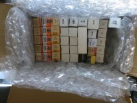
Just note that I got a parcel from a Swiss Tubeophile with some dozens of tubes borrowed, for the sake of creating tube spice models based on this tubes.
I'm happy to see several of each type, so that I can select the most representative one for spice model fitting.
So, I will interrupt my "Russian NOS tube program" (see my post #2737) and priorize this borrowed West tubes.
In addition, a parcel with a bunch of ECC86 tubes, also borrowed for the same sake, is on the way
@ Zonnebloem,
I can offer you a PC97 model in two weeks, if that is ok for you. At the moment, my "burn-in bench" is running a set of Philips 6922 tubes, so the PC97 tubes have to wait...
best regards, Adrian
Attachments
The world needs a killer 6922 / E88CC / ECC88 / 6DJ8 model!
The PC97 model will be most welcome too. I'm curious how that class of tube will model. I see there's also a sleeve of 6HM5 and a PC900. It will be interesting to see how different those turn out from PC97. They should all be pretty similar.
Cool beans!
The PC97 model will be most welcome too. I'm curious how that class of tube will model. I see there's also a sleeve of 6HM5 and a PC900. It will be interesting to see how different those turn out from PC97. They should all be pretty similar.
Cool beans!
Hi all
Here the last Russian NOS spice model, before I switch to the parcel mentioned in my last post...
It's the 6N14P, intended for cascode circuits. Model matched to the most representative out of 10 burned in triodes.
best regards, Adrian
Here the last Russian NOS spice model, before I switch to the parcel mentioned in my last post...
It's the 6N14P, intended for cascode circuits. Model matched to the most representative out of 10 burned in triodes.
best regards, Adrian
Code:
*6N14P LTspice model based on the generic triode model from Adrian Immler, version i4
*A version log is at the end of this file
*100h BurnIn of 5 Reflector factory tubes, sample selection and measurements done in April 2021
*Params fitted to the measured values by Adrian Immler, April 2021
*The high fit quality is presented at adrianimmler.simplesite.com
*History's best of tube decribing art (plus some new ideas) is merged to this new approach.
*@ neg. Vg, Ia accuracy is similar to Koren.
*@ small neg. Vg, the "Anlauf" current is considered.
*@ pos. Vg, Ig and Ia accuracy is on a unrivaled level.
*This offers new simulation possibilities like bias point setting with MOhm grid resistor,
*Audion radio circuits, low voltage amps, guitar distortion stages or pulsed stages.
*             adjusted i4 version
*             |  anode (plate)
*             |  | grid
*             |  | | cathode
*             |  | | |
.subckt 6N14P.i4 A G K
+ params:
*Parameters for the space charge current @ Vg <= 0
+ mu   = 27    ;Determines the voltage gain @ constant Ia
+ rad  = 2k46  ;Differential anode resistance, set @ Iad and Vg=0V
+ Vct  = 0.4   ;Offsets the Ia-traces on the Va axis. Electrode material's contact potential
+ kp   = 132   ;Mimics the island effect
+ xs   = 1.37  ;Determines the curve of the Ia traces. Typically between 1.2 and 1.8
*
*Parameters for assigning the space charge current to Ia and Ig @ Vg > 0
+ kB   = 1.1   ;Describes how fast Ia drops to zero when Va approaches zero.
+ radl = 150   ;Differential resistance for the Ia emission limit @ very small Va and Vg > 0
+ tsh  = 8     ;Ia transmission sharpness from 1th to 2nd Ia area. Keep between 3 and 20. Start with 20.
+ xl   = 1.2   ;Exponent for the emission limit
*
*Parameters of the grid-cathode vacuum diode
+ kvdg  = 65   ;virtual vacuumdiode. Causes an Ia reduction @ Ig > 0.
+ kg = 1k1     ;Inverse scaling factor for the Va independent part of Ig (caution - interacts with xg!)
+ Vctg = 0.0   ;Offsets the log Ig-traces on the Vg axis. Electrode material's contact potential
+ xg   = 1.5   ;Determines the curve of the Ig slope versus (positive) Vg and Va >> 0
+ VT   = 0.13  ;Log(Ig) slope @ Vg<0. VT=k/q*Tk (cathodes absolute temp, typically 1150K)
+ kVT=30m      ;Va dependant koeff. of VT
+ Vft2 = 0 gft2 = 0;finetunes the gridcurrent @ low Va and Vg near zero
*
*Parameters for the caps
+ cag  = 0p25  ;From datasheet (valid for 1 triode; for second triode use 1p8)
+ cak  = 2p8   ;From datasheet (valid for 1 triode; for second triode use 1p15)
+ cgk  = 4p7   ;From datasheet (valid for 1 triode; for second triode use 2p55)
*
*special purpose parameters
+ os = 1       ;Overall scaling factor, if a user wishes to simulate manufacturing tolerances
*
*Calculated parameters
+ Iad = {100/rad} ;Ia where the anode a.c. resistance is set according to rad.
+ ks = {pow(mu/(rad*xs*Iad**(1-1/xs)),-xs)} ;Reduces the unwished xs influence to the Ia slope
+ ksnom = {pow(mu/(rad*1.5*Iad**(1-1/1.5)),-1.5)} ;Sub-equation for calculating Vg0
+ Vg0 = {Vct + (Iad*ks)**(1/xs) - (Iad*ksnom)**(2/3)} ;Reduces the xs influence to Vct.
+ kl = {pow(1/(radl*xl*Ild**(1-1/xl)),-xl)} ;Reduces the xl influence to the Ia slope @ small Va
+ Ild = {sqrt(radl)*1m} ;Current where the Il a.c. resistance is set according to radl.
*
*Space charge current model
Bggi GGi 0 V=v(Gi,K)+Vg0 ;Effective internal grid voltage.
Bahc Ahc 0 V=uramp(v(A,K)) ;Anode voltage, hard cut to zero @ neg. value
Bst   St 0 V=uramp(max(v(GGi)+v(A,K)/(mu), v(A,K)/kp*ln(1+exp(kp*(1/mu+v(GGi)/(1+v(Ahc)))))));Steering volt.
Bs    Ai K I=os/ks*pow(v(St),xs) ;Langmuir-Childs law for the space charge current Is
*
*Anode current limit @ small Va
.func smin(z,y,k) {pow(pow(z+1f, -k)+pow(y+1f, -k), -1/k)} ;Min-function with smooth trans.
Ra  A Ai 1
Bgl Gi A I=min(i(Ra)-smin(1/kl*pow(v(Ahc),xl),i(Ra),tsh),i(Bgvd)*exp(4*v(G,K))) ;Ia emission limit
*
*Grid model
Bvdg G Gi I=1/kvdg*pwrs(v(G,Gi),1.5) ;Reduces the internal effective grid voltage when Ig rises
Rgip G Gi 1G ;avoids some warnings
Cvdg G Gi 0p1;this small cap improves convergence
.func fVT() {VT*exp(-kVT*sqrt(v(A,K)))}
.func Ivd(Vvd, kvd, xvd, VTvd)  {if(Vvd < 3, 1/kvd*pow(VTvd*xvd*ln(1+exp(Vvd/VTvd/xvd)),xvd), 1/kvd*pow(Vvd, xvd))} ;Vacuum diode function
Bgvd Gi K I=Ivd(v(G,K) + Vctg, kg/os, xg, fVT())
.func ft2() {gft2*(1-tanh(3*(v(G,K)+Vft2)))} ;Finetuning-func. improves ig-fit @ Vg near -0.5V, low Va.
Bgr Gi Ai I=ivd(v(GGi),ks/os, xs, 0.8*VT)/(1+ft2()+kB*v(Ahc));Is reflection to grid when Va approaches zero
Bs0 Ai K  I=ivd(v(GGi),ks/os, xs, 0.8*VT)/(1+ft2()) - os/ks*pow(v(GGi),xs) ;Compensates neg Ia @ small Va and Vg near zero
*
*Caps
C1 A G {cag}
C2 A K {cak}
C3 G K {cgk}
.ends
*
*Version log
*i1 :Initial version
*i2 :Pin order changed to the more common order A G K (Thanks to Markus Gyger for his tip)
*i3 :bugfix of the Ivd-function: now also usable for larger Vvd
*i4: Rgi replaced by a virtual vacuum diode (better convergence). ft1 deleted (no longer needed)
;2 new prarams for Ig finetuning @ Va and Vg near zero. New overall skaling factor os for aging etc.
Attachments
I have several 6DJ8 models.The world needs a killer 6922 / E88CC / ECC88 / 6DJ8 model!
--
Cool beans!
But I am not at all sure which model is the best/correct.
I would love a good 6DJ8 spice model, too.
I run Multisim simulator.
Here is a good 6DJ8 spice model.The world needs a killer 6922 / E88CC / ECC88 / 6DJ8 model!
It is advanced and I have tested it.
Enjoy!
Code:
.subckt 6dj8 1 2 3 ; p g c; new model
+ params: mu=28 ex=1.3 kg1=330 kp=320 kvb=300 rgi=2000
+ ccg=2.3p cgp=2.1p ccp=.7p ; add .7pf to adjacent pins; .5 to others.
e1 7 0 value=
+{v(1,3)/kp*ln(1+exp(kp*(1/mu+v(2,3)/sqrt(kvb+v(1,3)*v(1,3)))))}
re1 7 0 1g
g1 1 3 value={(pwr(v(7),ex)+pwrs(v(7),ex))/kg1}
rcp 1 3 1g ; to avoid floating nodes in mu-follower
c1 2 3 {ccg} ; cathode-grid; was 1.6p
c2 2 1 {cgp} ; grid-plate; was 1.5p
c3 1 3 {ccp} ; cathode-plate; was 0.5p
d3 5 3 dx ; for grid current
r1 2 5 {rgi} ; for grid current
.model dx d(is=1n rs=1 cjo=10pf tt=1n)
.endsThis is a E88CC model.The world needs a killer 6922 / E88CC / ECC88 / 6DJ8 model!
My testrun shows it is good.
Code:
.subckt e88cc 1 2 3
+ params: mu=36.34 ex=1.35 kg1=129.3 kp=292.92 kvb=217.61
+ rgi=2000
+ ccg=3.1p cgp=1.4p ccp=0.18p

e1 7 0 value={v(1,3)/kp*ln(1+exp(kp*(1/mu+v(2,3)/sqrt(kvb+v(1,3)*v(1,3)))))}
re1 7 0 1g
g1 1 3 value={ (pwr(v(7),ex)+pwrs(v(7), ex))/(2*kg1) }
rcp 1 3 1g ; to avoid floating nodes in mu-follower
c1 2 3 {ccg} ; cathode grid
c2 2 1 {cgp} ; grid-plate
c3 1 3 {ccp} ; cathode-plate
d3 5 3 dx ; for grid current
r1 2 5 {rgi} ; for grid current
.model dx d(is=1n rs=1 cjo=10pf tt=1n)
.endsCan you tell us the source of these two models?
-----
It is:
paengdesign
Spice Model Package 7/7 Triodes
Link: paengdesign | Research Design Engineering for Audio Nation
-----
It is:
paengdesign
Spice Model Package 7/7 Triodes
Link: paengdesign | Research Design Engineering for Audio Nation
Hi all
Just want to give you an update what's going on with my borrowed west tubes.
In the meantime the PhilipsECG 6922 as well as the electro-harmonix 6922 are burnt in. I couldn't burnin both types in parallel, as my bench allowes max. 6 noval-based tubes...
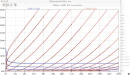
All the PhilipsECG 6922 are now measured and a golden Sample is selected, but I hesitated to create a spicemodel, as I realized that the EH 6922s construction is not identical but similar, so there was a certain chance that the EH would deliver the same behaviour - and selecting a golden Sample out of 20 instead of 10 is much better, it will be representative in much more aspects.
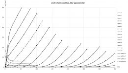
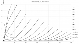
This morning, I measured the first EH 6922, and it turned out that it behaves different:
-a bit larger mu
-more linear (less "bendy")
-by far less present island effect (=the extra rounded kinks at high Va values)
-needs a bit less grid current for same positive grid voltage
So, it is better to generate TWO 6922 models.
The PhilipsECG 6922 will be generated the next days.
The EH 6922 will need a bit more time. I first have to measure all and select best sample.
best regards, Adrian
PS: The PC97 tubes and also the ECC86 tubes (generously borrowed from lineup!) are burning in. PC97 is on half way to the goal of 100 hours!
Just want to give you an update what's going on with my borrowed west tubes.
In the meantime the PhilipsECG 6922 as well as the electro-harmonix 6922 are burnt in. I couldn't burnin both types in parallel, as my bench allowes max. 6 noval-based tubes...
All the PhilipsECG 6922 are now measured and a golden Sample is selected, but I hesitated to create a spicemodel, as I realized that the EH 6922s construction is not identical but similar, so there was a certain chance that the EH would deliver the same behaviour - and selecting a golden Sample out of 20 instead of 10 is much better, it will be representative in much more aspects.
This morning, I measured the first EH 6922, and it turned out that it behaves different:
-a bit larger mu
-more linear (less "bendy")
-by far less present island effect (=the extra rounded kinks at high Va values)
-needs a bit less grid current for same positive grid voltage
So, it is better to generate TWO 6922 models.
The PhilipsECG 6922 will be generated the next days.
The EH 6922 will need a bit more time. I first have to measure all and select best sample.
best regards, Adrian
PS: The PC97 tubes and also the ECC86 tubes (generously borrowed from lineup!) are burning in. PC97 is on half way to the goal of 100 hours!
Attachments
Last edited:

- Home
- Amplifiers
- Tubes / Valves
- Vacuum Tube SPICE Models