I should say 'lift under'. And the '5' is missing from "6HA5 3f4 Spice model:". It's been a long night...I like how the curves of the 6HA5 look in the high Vg-Vp region (they don't curve under), but not too happy about the 0Vg curve.

I think you are referring to the Ayumi pctube library, if so, *.inc is for PSpice, *.mod is for SIMetrix. As mentioned, to use the *.inc models in LTSpice, you need to replace all the "^" with "**".
That helps. Thanks!
Spice models for RS1019 and PL36
I think this is best place to ask. My son have shown interest to tube amplifiers. We have started to learn things with Microcap. Microcap have some tube models and I have also installed Korren model library. We however have some odd tubes to play with. Line output pentodes PL36 and Siemens RS1019 TX tetrodes. Do anyone possibly have spice models for these? PL36 is of cource same as EL36 Siemens RS1019 is same as QQE03/20 or Telefunken 6252 Telefunken data sheet seems to contain most information about this tube. Juha
I think this is best place to ask. My son have shown interest to tube amplifiers. We have started to learn things with Microcap. Microcap have some tube models and I have also installed Korren model library. We however have some odd tubes to play with. Line output pentodes PL36 and Siemens RS1019 TX tetrodes. Do anyone possibly have spice models for these? PL36 is of cource same as EL36 Siemens RS1019 is same as QQE03/20 or Telefunken 6252 Telefunken data sheet seems to contain most information about this tube. Juha
EL36/PL36 SPICE Model
Not perfect, but it's about as close I can get...
Not perfect, but it's about as close I can get...
Code:
*
* Generic pentode model: EL36_AN
* Copyright 2003--2008 by Ayumi Nakabayashi, All rights reserved.
* Version 3.10, Generated on Tue Jan 14 10:23:19 2014
*               Plate
*               | Screen Grid
*               | | Control Grid
*               | | | Cathode
*               | | | |
.SUBCKT EL36_AN A G2 G1 K
BGG   GG   0 V=V(G1,K)+1
BM1   M1   0 V=(0.062823603*(URAMP(V(G2,K))+1e-10))**-0.63677761
BM2   M2   0 V=(0.70199163*(URAMP(V(GG)+URAMP(V(G2,K))/4.7435734)))**2.1367776
BP    P    0 V=0.004449656*(URAMP(V(GG)+URAMP(V(G2,K))/6.7573076))**1.5
BIK   IK   0 V=U(V(GG))*V(P)+(1-U(V(GG)))*0.0025785721*V(M1)*V(M2)
BIG   IG   0 V=0.002224828*URAMP(V(G1,K))**1.5*(URAMP(V(G1,K))/(URAMP(V(A,K))+URAMP(V(G1,K)))*1.2+0.4)
BIK2  IK2  0 V=V(IK,IG)*(1-0.4*(EXP(-URAMP(V(A,K))/URAMP(V(G2,K))*15)-EXP(-15)))
BIG2T IG2T 0 V=V(IK2)*(0.960918328*(1-URAMP(V(A,K))/(URAMP(V(A,K))+10))**1.5+0.039081672)
BIK3  IK3  0 V=V(IK2)*(URAMP(V(A,K))+875)/(URAMP(V(G2,K))+875)
BIK4  IK4  0 V=V(IK3)-URAMP(V(IK3)-(0.0032482599*(URAMP(V(A,K))+URAMP(URAMP(V(G2,K))-URAMP(V(A,K))))**1.5))
BIP   IP   0 V=URAMP(V(IK4,IG2T)-URAMP(V(IK4,IG2T)-(0.0032482599*URAMP(V(A,K))**1.5)))
BIAK  A    K I=V(IP)+1e-10*V(A,K)
BIG2  G2   K I=URAMP(V(IK4,IP))
BIGK  G1   K I=V(IG)
* CAPS
CGA   G1  A  1.1p
CGK   G1  K  10.8p
C12   G1  G2 7.2p
CAK   A   K  8p
.ENDStube data
Thank you. Bellow few links to the data sheets. There is not much available about Siemens RS-1019 RS 1019, Tube RS1019; Röhre RS 1019 ID28311, Double Tetrode kirppuja.fi/Literature/S/Siemens/Tubes/03/RS1019.pdf Equivalent Telefunken and Philips data sheets are better frank.pocnet.net/sheets/128/6/6252.pdf frank.pocnet.net/sheets/030/q/QQE03-20.pdf Two alternatives for Philips PL36 frank.pocnet.net/sheets/010/p/PL36.pdf frank.pocnet.net/sheets/030/p/PL36.pdf Good source for data if you did not already know electron Tube Data sheets - Q Juha PS I am sorry I do not know wht new line characters disappears from my posting
Thank you. Bellow few links to the data sheets. There is not much available about Siemens RS-1019 RS 1019, Tube RS1019; Röhre RS 1019 ID28311, Double Tetrode kirppuja.fi/Literature/S/Siemens/Tubes/03/RS1019.pdf Equivalent Telefunken and Philips data sheets are better frank.pocnet.net/sheets/128/6/6252.pdf frank.pocnet.net/sheets/030/q/QQE03-20.pdf Two alternatives for Philips PL36 frank.pocnet.net/sheets/010/p/PL36.pdf frank.pocnet.net/sheets/030/p/PL36.pdf Good source for data if you did not already know electron Tube Data sheets - Q Juha PS I am sorry I do not know wht new line characters disappears from my posting
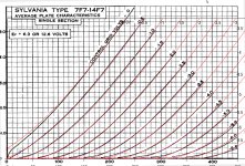
Got a fresh 7F7 model I generated based off http://www.jogis-roehrenbude.de/Roehren-Geschichtliches/Loctal-Roehren/7F7/7F7.pdf
reminder to ltspice users: replace all "^"'s with **
I haven't tested this in ltspice because I'm not sure how to do it
reminder to ltspice users: replace all "^"'s with **
Code:
*
* Generic triode model: 7F7
* Copyright 2003--2008 by Ayumi Nakabayashi, All rights reserved.
* Version 3.10, Generated on Tue Jan 14 10:59:43 2014
*           Plate
*           | Grid
*           | | Cathode
*           | | |
.SUBCKT 7F7 A G K
BGG   GG   0 V=V(G,K)+0.66534914
BM1   M1   0 V=(0.0017376631*(URAMP(V(A,K))+1e-10))^-0.1908445
BM2   M2   0 V=(0.88713066*(URAMP(V(GG)+URAMP(V(A,K))/64.954673)+1e-10))^1.6908445
BP    P    0 V=0.00073891459*(URAMP(V(GG)+URAMP(V(A,K))/73.218835)+1e-10)^1.5
BIK   IK   0 V=U(V(GG))*V(P)+(1-U(V(GG)))*0.00049855131*V(M1)*V(M2)
BIG   IG   0 V=0.0003694573*URAMP(V(G,K))^1.5*(URAMP(V(G,K))/(URAMP(V(A,K))+URAMP(V(G,K)))*1.2+0.4)
BIAK  A    K I=URAMP(V(IK,IG)-URAMP(V(IK,IG)-(0.00038464666*URAMP(V(A,K))^1.5)))+1e-10*V(A,K)
BIGK  G    K I=V(IG)
* CAPS
CGA   G    A 1.6p
CGK   G    K 2.4p
CAK   A    K 2p
.ENDSAttachments
Has anyone tried the 71A spice model form the Ayumi pctube library?
*
* Generic triode model: 71A
* Copyright 2003--2008 by Ayumi Nakabayashi, All rights reserved.
* Version 3.10, Generated on Sat Mar 8 22:41:45 2008
* Plate
* | Grid
* | | Cathode
* | | |
.SUBCKT 71A A G K
BGG GG 0 V=V(G,K)+-0.99999999
BM1 M1 0 V=(0.058225528*(URAMP(V(A,K))+1e-10))^-0.29538374
BM2 M2 0 V=(0.83547598*(URAMP(V(GG)+URAMP(V(A,K))/2.8256337)+1e-10))^1.7953837
BP P 0 V=0.00034434696*(URAMP(V(GG)+URAMP(V(A,K))/3.3820645)+1e-10)^1.5
BIK IK 0 V=U(V(GG))*V(P)+(1-U(V(GG)))*0.00021307994*V(M1)*V(M2)
BIG IG 0 V=0.00017217348*URAMP(V(G,K))^1.5*(URAMP(V(G,K))/(URAMP(V(A,K))+URAMP(V(G,K)))*1.2+0.4)
BIAK A K I=URAMP(V(IK,IG)-URAMP(V(IK,IG)-(0.00033568367*URAMP(V(A,K))^1.5)))+1e-10*V(A,K)
BIGK G K I=V(IG)
* CAPS
CGA G A 7.5p
CGK G K 3.2p
CAK A K 2.9p
.ENDS
I get strange results with it. Simple triode gain stage with 1600R in the cathode and 10K in the anode biases with the anode above the anode supply (Va=200V), and the cathode at 1.2KV!
Try this as Micro-Cap uses LIMIT(x,min,max) instead of URAMP.Where is the variable URAMP defined and what value range is expected?
Juha
Code:
* Generic pentode model: EL36_AN
* Copyright 2003--2008 by Ayumi Nakabayashi, All rights reserved.
* Version 3.10, Generated on Tue Jan 14 10:23:19 2014
*               Plate
*               | Screen Grid
*               | | Control Grid
*               | | | Cathode
*               | | | |
.SUBCKT EL36_AN A G2 G1 K
BGG   GG   0 V=V(G1,K)+1
BM1   M1   0 V=(0.062823603*(LIMIT(V(G2,K),0,1e16)+1e-10))**-0.63677761
BM2   M2   0 V=(0.70199163*(LIMIT((V(GG)+LIMIT(V(G2,K),0,1e16)/4.7435734),0,1e16)))**2.1367776
BP    P    0 V=0.004449656*(LIMIT((V(GG)+LIMIT(V(G2,K),0,1e16)/6.7573076),0,1e16))**1.5
BIK   IK   0 V=STP(V(GG))*V(P)+(1-STP(V(GG)))*0.0025785721*V(M1)*V(M2)
BIG   IG   0 V=0.002224828*LIMIT(V(G1,K),0,1e16)**1.5*(LIMIT(V(G1,K),0,1e16)/(LIMIT(V(A,K),0,1e16)+LIMIT(V(G1,K),0,1e16))*1.2+0.4)
BIK2  IK2  0 V=V(IK,IG)*(1-0.4*(EXP(-LIMIT(V(A,K),0,1e16)/LIMIT(V(G2,K),0,1e16)*15)-EXP(-15)))
BIG2T IG2T 0 V=V(IK2)*(0.960918328*(1-LIMIT(V(A,K),0,1e16)/(LIMIT(V(A,K),0,1e16)+10))**1.5+0.039081672)
BIK3  IK3  0 V=V(IK2)*(LIMIT(V(A,K),0,1e16)+875)/(LIMIT(V(G2,K),0,1e16)+875)
BIK4  IK4  0 V=V(IK3)-LIMIT(V(IK3)-(0.0032482599*(LIMIT(V(A,K),0,1e16)+LIMIT(LIMIT(V(G2,K),0,1e16)-LIMIT(V(A,K),0,1e16),0,1e16))**1.5),0,1e16)
BIP   IP   0 V=LIMIT(V(IK4,IG2T)-LIMIT(V(IK4,IG2T)-(0.0032482599*LIMIT(V(A,K),0,1e16)**1.5),0,1e16),0,1e16)
BIAK  A    K I=V(IP)+1e-10*V(A,K)
BIG2  G2   K I=LIMIT(V(IK4,IP),0,1e16)
BIGK  G1   K I=V(IG)
* CAPS
CGA   G1  A  1.1p
CGK   G1  K  10.8p
C12   G1  G2 7.2p
CAK   A   K  8p
.ENDS
Last edited:
If you have a "failed to converge..." or "Matrix is singular" error, try changing this line:
BM1 M1 0 V=(0.062823603*(LIMIT(V(G2,K),0,1e16)+1e-10))**-0.63677761
to:
BM1 M1 0 V=(0.062823603*(LIMIT(V(G2,K),0,1e16)+1e-03))**-0.63677761
and possibly you can try to change all limit(x,0,1e16) values to limit(x,0,1e3) or some other maximum value.
BM1 M1 0 V=(0.062823603*(LIMIT(V(G2,K),0,1e16)+1e-10))**-0.63677761
to:
BM1 M1 0 V=(0.062823603*(LIMIT(V(G2,K),0,1e16)+1e-03))**-0.63677761
and possibly you can try to change all limit(x,0,1e16) values to limit(x,0,1e3) or some other maximum value.
Tube data (mail format corrected)
Bellow few links to the data sheets.
There are not much available about Siemens RS-1019
RS 1019, Tube RS1019; Röhre RS 1019 ID28311, Double Tetrode
Siemens RS1019
Equivalent Telefunken and Philips data sheets are better
Telefunken 6252
QQE03-20
Two alternatives for Philips PL36
PL36_1
fPL36_2
Good source for data if you did not already know
electron Tube Data sheets - Q
Juha
PS mail formatting corrected after I changed my profile to text only mode. Unfortunately I could not edit and correct the original post.
Which simulator are you using?
I'm using LTSpice.
Did you change all instances of ^ to **?I'm using LTSpice.
A Spice test model
Here's something that might interest some of the readers of this thread.
I use SiMetrix very often but I never try to create my own tube model and I just begin to study how to do. I found a trick to test models without having to edit the library file and "Re-Build catalog" every time I make a change. I create a very simple test Spice model.
Suppose you like to see what kind of current curve give this model with a 0.1 exponent :
.SUBCKT CURVE 1 G
B1 1 G I=V(1,G)^0.1
.ENDS
I create the next model to be able to test more complex models without having to write all the parameters but just passing them in a voltage form :
.SUBCKT TEST_CURVE 1 2 3 4 5 6 7 G
B1 1 G I=V(1,G)^V(2,G)
.ENDS
There is much more pins than needed but they don't have to be all used, the voltage across the model is between pins 1 and G like in the first model and the voltage representing the exponent between pins 2 and G. I associate the model to a automatically created 8 pins symbol and draw this little test circuit :
Then I choose the analysis permitting the current curve drawing, a sweep linear 0 to 1 VDC from device V1 with 1000 plot points :
Here's the curve you get when running the simulation with device V2 set at 0.1V, representing the 0.1 exponent in the model :
This curve look like a pentode or semiconductor curve. SiMetrix have a very useful feature for curves drawing, when you check the "Enable muti-step" case in the "Choose Analysis" dialog box and click on the "Define" button, the "Define Multi Step Analysis" dialog box appear :
As you can see, the multiple linear steps concern the V2 device, I choice 0V to 2V in 20 steps ... I should make it 21 steps to get 0.1V between each curves but that will do for the demonstration ... here's the result :
This way, you can easily pass as much parameters you need to test your models, just add some pins if needed. It is much faster than editing the model every time you make a small change, it is perfect for a tuning job, you just have to change the voltage of the concerned DC voltage sources or generate a bunch of curves to see which one fit what you need ...
Notice the multi step analysis is also very useful to draw the curves of any tubes models at any grid voltage you like.
Here's something that might interest some of the readers of this thread.
I use SiMetrix very often but I never try to create my own tube model and I just begin to study how to do. I found a trick to test models without having to edit the library file and "Re-Build catalog" every time I make a change. I create a very simple test Spice model.
Suppose you like to see what kind of current curve give this model with a 0.1 exponent :
.SUBCKT CURVE 1 G
B1 1 G I=V(1,G)^0.1
.ENDS
I create the next model to be able to test more complex models without having to write all the parameters but just passing them in a voltage form :
.SUBCKT TEST_CURVE 1 2 3 4 5 6 7 G
B1 1 G I=V(1,G)^V(2,G)
.ENDS
There is much more pins than needed but they don't have to be all used, the voltage across the model is between pins 1 and G like in the first model and the voltage representing the exponent between pins 2 and G. I associate the model to a automatically created 8 pins symbol and draw this little test circuit :
An externally hosted image should be here but it was not working when we last tested it.
Then I choose the analysis permitting the current curve drawing, a sweep linear 0 to 1 VDC from device V1 with 1000 plot points :
An externally hosted image should be here but it was not working when we last tested it.
Here's the curve you get when running the simulation with device V2 set at 0.1V, representing the 0.1 exponent in the model :
An externally hosted image should be here but it was not working when we last tested it.
This curve look like a pentode or semiconductor curve. SiMetrix have a very useful feature for curves drawing, when you check the "Enable muti-step" case in the "Choose Analysis" dialog box and click on the "Define" button, the "Define Multi Step Analysis" dialog box appear :
An externally hosted image should be here but it was not working when we last tested it.
As you can see, the multiple linear steps concern the V2 device, I choice 0V to 2V in 20 steps ... I should make it 21 steps to get 0.1V between each curves but that will do for the demonstration ... here's the result :
An externally hosted image should be here but it was not working when we last tested it.
This way, you can easily pass as much parameters you need to test your models, just add some pins if needed. It is much faster than editing the model every time you make a small change, it is perfect for a tuning job, you just have to change the voltage of the concerned DC voltage sources or generate a bunch of curves to see which one fit what you need ...
Notice the multi step analysis is also very useful to draw the curves of any tubes models at any grid voltage you like.
- Home
- Amplifiers
- Tubes / Valves
- Vacuum Tube SPICE Models