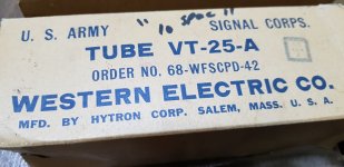
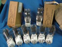
See there is Western Electric own made WE "VT-25" and "VT-25-A" in this image? The -A version is made also by Hytron for Wstern Electric, seems VT-25-A is not uplated VT-25 & just a VT-25 with oxide-coated filament .Some said the curve would be different, but curve is not updated? Practical test measurement can show the differences, I hope.
Attachments
Last edited:
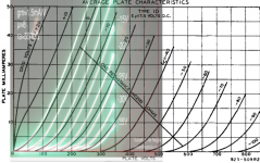
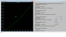
Here is the model with grid current based on original curve found on left bottom corner.
Code:**** 6N2P ** Advanced Grid Current ********************************** * Created on 05/28/2020 23:43 using paint_kit.jar 3.1 * [URL="http://www.dmitrynizh.com/tubeparams_image.htm"]Model Paint Tools: Trace Tube Parameters over Plate Curves, Interactively[/URL] * Plate Curves image file: 6n2p.png * Data source link: *---------------------------------------------------------------------------------- .SUBCKT 6N2P 1 2 3 ; Plate Grid Cathode + PARAMS: CCG=2P CGP=0.7P CCP=2.3P + MU=115.1 KG1=1406.05 KP=438.01 KVB=397.54 VCT=0.6005 EX=1.46 + VGOFF=-1.029 IGA=5.168E-4 IGB=0.07855 IGC=100.02 IGEX=1.958 * Vp_MAX=440 Ip_MAX=4 Vg_step=0.5 Vg_start=1 Vg_count=12 * Rp=4000 Vg_ac=55 P_max=1 Vg_qui=-48 Vp_qui=300 * X_MIN=130 Y_MIN=3 X_SIZE=1179 Y_SIZE=842 FSZ_X=1798 FSZ_Y=965 XYGrid=true * showLoadLine=n showIp=y isDHT=n isPP=n isAsymPP=n showDissipLimit=y * showIg1=y gridLevel2=y isInputSnapped=n * XYProjections=n harmonicPlot=n dissipPlot=n *---------------------------------------------------------------------------------- E1 7 0 VALUE={V(1,3)/KP*LOG(1+EXP(KP*(1/MU+(VCT+V(2,3))/SQRT(KVB+V(1,3)*V(1,3)))))} RE1 7 0 1G ; TO AVOID FLOATING NODES G1 1 3 VALUE={(PWR(V(7),EX)+PWRS(V(7),EX))/KG1} RCP 1 3 1G ; TO AVOID FLOATING NODES C1 2 3 {CCG} ; CATHODE-GRID C2 2 1 {CGP} ; GRID=PLATE C3 1 3 {CCP} ; CATHODE-PLATE RE2 2 0 1G EGC 8 0 VALUE={V(2,3)-VGOFF} ; POSITIVE GRID THRESHOLD GG 2 3 VALUE={(IGA+IGB/(IGC+V(1,3)))*(MU/KG1)*(PWR(V(8),IGEX)+PWRS(V(8),IGEX))} .ENDS *$
Fantastic job thanks...
")
There is a 6p44c triode connected curve here:
Кабинетный SE на 6П44С
You need an account to retrieve it. This will help a lot, you use paint.net to make an curve image with pentode and triode overlapping and in Paint tool turn on triode connected mode to adjust against the triode curve of the image.
Here are some more pentode triode trace curves
Attachments
AZ50 spice model
Just maked spice model for Philips AZ50.
Next step is install it in my amp, because Siemens GZ34 was finished after a long time.
.model AZ50 D(Is=1e-2 RS=204 Cjo=30p vj=2 N=23 bv=1550 mfg=Philips type=vacuum )
Just maked spice model for Philips AZ50.
Next step is install it in my amp, because Siemens GZ34 was finished after a long time.
.model AZ50 D(Is=1e-2 RS=204 Cjo=30p vj=2 N=23 bv=1550 mfg=Philips type=vacuum )
Attachments
Ray, here is:
.model GZ34 D(Is=1e-2 RS=36 Cjo=30p vj=2 N=80 bv=1500 mfg=TFK type=vacuum )
.model 6X4 D(Is=1e-2 RS=121 Cjo=20p vj=2 N=256 bv=1250 mfg=RCA type=vacuum )
.model 5R4GY D(Is=1e-2 RS=150 Cjo=30p vj=2 N=305 bv=3100 mfg=RCA type=vacuum )
.model EZ81 D(Is=1e-2 RS=53 Cjo=5p vj=2 N=163 bv=330 mfg=Mazda type=vacuum )
Maybe the thread isn't for this, but ...
AZ50 has the smallest voltage drop after the GZ34 rectifier, as far as I know.
Ik is only 2 mA smaller through my =C= 300B.
Sound is great. Bass may be a little less defined, but the mids and highs are beautiful. I expect more improvements after my Philips AZ50 "sits down"
Guys, if you have a Philips AZ50, go ahead.
And yes, spice model is OK.
Moderators, if you think this post is unnecessary, delete it. No problem.
Thanks Adrian. I'm looking forward to your 12AX7/ECC83 model.
Hi cogsnogs
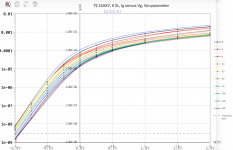
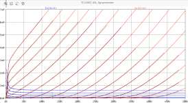
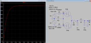
It took some time to create the Tung-Sol 12AX7 spice model, but the result has really not to be hidden!
It is based on detailed measurements from a "golden sample" out of 5 burnt-in and quality-tested tubes. "golden Sample" means this triode, which showes best match to the data sheet.
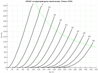
As you can see in the log(Ig) graph, my model copes to mimic the initial velocity grid current (the linear slopes at the left side of the graph), so that means you will be able to simulate biasing with grid resistor (e.g. 20 MOhm or so).
Be aware that this kind of bias setting is NOT (!!) recommended with JJ ECC83S tubes - my measurements showed extreme grid current tolerances for this tubes.
all the best, Adrian
Code:
*12AX7 LTspice model based on the generic triode model from Adrian Immler, version i4
*A version log is at the end of this file
*selection out of 5 new burnt-in Tung-Sol tubes and measurements done in May 2020
*Params fitted to the measured values by Adrian Immler, June 2020
*The high fit quality is presented at adrianimmler.simplesite.com
*History's best of tube decribing art (plus some new ideas) is merged to this new approach.
*@ neg. Vg, Ia accuracy is similar to Koren or Ayumi models.
*@ small neg. Vg, the "Anlauf" current is considered.
*@ pos. Vg, Ig and Ia accuracy is on a unrivaled level.
*This offers new simulation possibilities like bias point setting with MOhm grid resistor,
*Audion radio circuits, low voltage amps, guitar distortion stages or pulsed stages.
* anode (plate)
* | grid
* | | cathode
* | | |
.subckt 12AX7.TSi4 A G K
.params
*Parameters for the space charge current @ Vg <= 0
+ mu = 94.3 ;Determines the voltage gain @ constant Ia
+ rad = 39k2 ;Differential anode resistance, set @ Iad and Vg=0V
+ Vct = 0.28 ;Offsets the Ia-traces on the Va axis. Electrode material's contact potential
+ kp = 950 ;Mimics the island effect
+ xs = 1.5 ;Determines the curve of the Ia traces. Typically between 1.2 and 1.8
*
*Parameters for assigning the space charge current to Ia and Ig @ Vg > 0
+ kB = 0.9 ;Describes how fast Ia drops to zero when Va approaches zero.
+ radl = 750 ;Differential resistance for the Ia emission limit @ very small Va and Vg > 0
+ tsh = 12 ;Ia transmission sharpness from 1th to 2nd Ia area. Keep between 3 and 20. Start with 20.
+ xl = 1.5 ;Exponent for the emission limit
*
*Parameters of the grid-cathode vacuum diode
+ kvdg = 450 ;virtual vacuumdiode. Causes an Ia reduction @ Ig > 0.
+ kg = 5k2 ;Inverse scaling factor for the Va independent part of Ig (caution - interacts with xg!)
+ Vctg = 0.1 ;Offsets the log Ig-traces on the Vg axis. Electrode material's contact potential
+ xg = 1.5 ;Determines the curve of the Ig slope versus (positive) Vg and Va >> 0
+ VT = 0.1 ;Log(Ig) slope @ Vg<0. VT=k/q*Tk (cathodes absolute temp, typically 1150K)
+ Vft2 = -0.1 gft2 = 0;finetunes the gridcurrent @ low Va and Vg near zero
*
*Parameters for the caps
+ cag = 1p7 ;From datasheet
+ cak = 0p34 ;From datasheet
+ cgk = 1p6 ;From datasheet
*
*special purpose parameters
+ os = 1 ;Overall scaling factor, if a user wishes to simulate manufacturing tolerances
*
*Calculated parameters
+ Iad = 100/rad ;Ia where the anode a.c. resistance is set according to rad.
+ ks = pow(mu/(rad*xs*Iad**(1-1/xs)),-xs) ;Reduces the unwished xs influence to the Ia slope
+ ksnom = pow(mu/(rad*1.5*Iad**(1-1/1.5)),-1.5) ;Sub-equation for calculating Vg0
+ Vg0 = Vct + (Iad*ks)**(1/xs) - (Iad*ksnom)**(2/3) ;Reduces the xs influence to Vct.
+ kl = pow(1/(radl*xl*Ild**(1-1/xl)),-xl) ;Reduces the xl influence to the Ia slope @ small Va
+ Ild = sqrt(radl)*1m ;Current where the Il a.c. resistance is set according to radl.
*
*Space charge current model
Bggi GGi 0 V=v(Gi,K)+Vg0 ;Effective internal grid voltage.
Bahc Ahc 0 V=uramp(v(A,K)) ;Anode voltage, hard cut to zero @ neg. value
Bst St 0 V=uramp(max(v(GGi)+v(A,K)/(mu), v(A,K)/kp*ln(1+exp(kp*(1/mu+v(GGi)/(1+v(Ahc)))))));Steering volt.
Bs Ai K I=os/ks*pow(v(St),xs) ;Langmuir-Childs law for the space charge current Is
*
*Anode current limit @ small Va
.func smin(z,y,k) {pow(pow(z+1f, -k)+pow(y+1f, -k), -1/k)} ;Min-function with smooth trans.
Ra A Ai 1
Bgl Gi A I=min(i(Ra)-smin(1/kl*pow(v(Ahc),xl),i(Ra),tsh),i(Bgvd)*exp(4*v(G,K))) ;Ia emission limit
*
*Grid model
Bvdg G Gi I=1/kvdg*pwrs(v(G,Gi),1.5) ;Reduces the internal effective grid voltage when Ig rises
Rgip G Gi 1G ;avoids some warnings
.func Ivd(Vvd, kvd, xvd, VTvd) {if(Vvd < 3, 1/kvd*pow(VTvd*xvd*ln(1+exp(Vvd/VTvd/xvd)),xvd), 1/kvd*pow(Vvd, xvd))} ;Vacuum diode function
Bgvd Gi K I=Ivd(v(G,K) + Vctg - uramp(-v(A,K)/mu), kg/os, xg, VT)
.func ft2() {gft2*(1-tanh(3*(v(G,K)+Vft2)))} ;Finetuning-func. improves ig-fit @ Vg near -0.5V, low Va.
Bgr Gi Ai I=ivd(v(GGi),ks/os, xs, 0.8*VT)/(1+ft2()+kB*v(Ahc));Is reflection to grid when Va approaches zero
Bs0 Ai K I=ivd(v(GGi),ks/os, xs, 0.8*VT)/(1+ft2()) - os/ks*pow(v(GGi),xs) ;Compensates neg Ia @ small Va and Vg near zero
*
*Caps
C1 A G {cag}
C2 A K {cak}
C3 G K {cgk}
.end
*
*Version log
*i1 :Initial version
*i2 :Pin order changed to the more common order âA G Kâ (Thanks to Markus Gyger for his tip)
*i3 :bugfix of the Ivd-function: now also usable for larger Vvd
*i4: Rgi replaced by a virtual vacuum diode (better convergence). ft1 deleted (no longer needed)
;2 new prarams for Ig finetuning @ Va and Vg near zero. New emission skaling factor ke for aging etc.Attachments
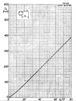
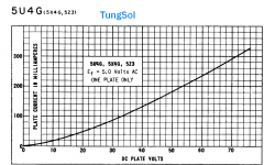
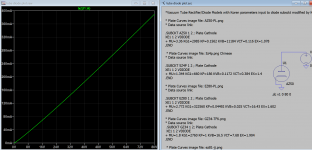
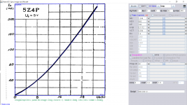
I wish to share with you all this new approach of mine to model vacuum rectifiers/diodes in attached VT-Diode.inc Vacuum Tube Rectifier/Diode modeled with Koren parameters input to diode sub-circuit adopted from triode model, i.e grid model is being excluded, left with only diode model, only Koren parameter is extracted from I/V rectifier curve using Paintool or ExtractModel.
Koonw.
Koonw.
Attachments
Last edited:
How to change PSUD2 model in LT spice model and vice versa.
Take for example the 6D22S tube rectifier.
PSUD2 model is:
VT, 0, 1.2646; 0.00677, 5000, 99, 1
In LT spice that model will be:
* 6D22S rectifier
.SUBCKT 6D22S 1 2
b1 1 2 i = 6.77E-3 * uramp (V (1,2)) ** 1.2646
Cpk 1 2 10P
.ends 6D22S
You can easily convert SUBCKT model in to PSUD2. Example with GZ30 (BTW, beautiful Mullard rectifier):
.SUBCKT GZ30 A K
* 3/2 power law, formulated as v * sqrt (v) for convergence
b1 A K i = 1.9e-3 * uramp (V (A, K)) ** 1.44
.ENDS GZ30
in to PSUD2 it will be:
VT, 0, 1.440, 0.00190, 1500, 99, 1
I hope I didn't make some typo. But I believe you understand me.
Mr Duncan, I hope you have nothing against this recommendation of mine.
Best DIYing
Last edited:
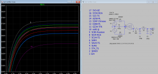
Some models run very slowly when sim, now I have used different value for the fitting the I/V curves, so here is the update version. I'll add more later so you can add any model as long as it has I/V curve in datasheet.I wish to share with you all this new approach of mine to model vacuum rectifiers/diodes in attached VT-Diode.inc Vacuum Tube Rectifier/Diode modeled with Koren parameters input to diode sub-circuit adopted from triode model, i.e grid model is being excluded, left with only diode model, only Koren parameter is extracted from I/V rectifier curve using Paintool or ExtractModel.
Koonw.
Attachments
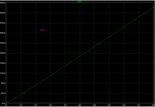
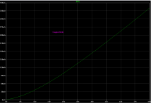
Convert /rectified AC to DC first using silicon, significantly speed up the simulation time.Some models run very slowly when sim, now I have used different value for the fitting the I/V curves, so here is the update version. I'll add more later so you can add any model as long as it has I/V curve in datasheet.
Attachments
Convert /rectified AC to DC first using silicon, significantly speed up the simulation time.
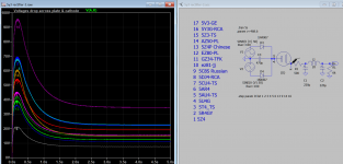
After gaining some speeds in simulation, I am finally able to plot something for sharing, hope you enjoy looking.
Attachments
- Home
- Amplifiers
- Tubes / Valves
- Vacuum Tube SPICE Models