Got a couple of these 6jd5 tubes to test with them, very inexpensive. Some may find use for it. Curves taken with beam plate tied to the plate. Traced with my home made curve tracer. I have no way of measuring grid current in my setup. The driver in the curve tracer starts giving up at 50ma which would be close to the top of curves. Using a LME49810.
Attachments
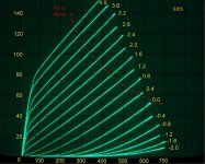
I've run some 6JD5 curves with +6 volts on the grid. Nothing melted, but they sure got warm.
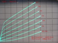
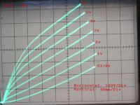
Some brands of 6JD5's have a really nice sharp low voltage knee, and others don't. I've got a project in the works using these in Class A2 or AB2 (haven't decided yet), and ran some curves on different brands: GE, Zenith, Sylvania, DuMont. The DuMont and Zenith were very similar with the knee at about 80 volts. The Sylvania had the knee at about 120 volts.
GE was the worst, with not much of a knee to speak of. In fact the GE curves didn't look remotely like the others, and I wonder if they just re-labeled a different tube as 6JD5.
Attachments
At the time, it never occurred to me to take grid current readings (I did these traces more than a year ago). I had to modify my homebrew tracer by adding a power MOSFET source follower to provide enough grid drive.
However, Joe Sousa posted 6JD5 traces on the RadioMuseum forum:
6JD5 Forward grid bias
He also ran a g1 I-V curve that shows about 40mA grid current when g1 voltage is +6V (worst case is with low plate voltage of 50V). Note, that his traces are labeled "6JD5 GE", but in an email exchange, he confirmed that it was a typo, and was actually a Sylvania tube.
In fact, it was Joe's work that originally sparked my interest in these tubes. He also ran curves for 6JK5, 6JH5, 6HV5 and 6HS5.
6JK5 Forward grid bias
6JH5 Forward grid bias
6HV5A Forward grid bias
6HS5 Forward grid bias
Notice that all of these other tubes are similar to the GE 6JD5 that I traced, in that none of them have a low voltage knee, making them less desirable for class A2 operation. And coincidentally, all of these other tubes that he traced were GE brand. I'm wondering if this may be a characteristic unique to the GE tubes, and maybe other brands such as Sylvania might have the more desirable low voltage knee.
At the time, it never occurred to me to take grid current readings (I did these traces more than a year ago). I had to modify my homebrew tracer by adding a power MOSFET source follower to provide enough grid drive.
Thanks Robert
Can you share your circuit of the mod? Did you use a source resistor or ccs?
Alfredo
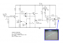
I used a 500 ohm source resistor. A CCS was unnecessary. The MOSFET is an NDP603 which was what I happened to have on hand. I've attached the circuit of my complete grid voltage step generator. The whole curve tracer is sync'd to power line frequency, so that I can use a simple AC line supply for the plate sweep voltage. Originally, my grid drive circuit was completely opposite polarity, and used a -15V supply and PNP transistors to generate negative grid voltages. And it didn't use the op amp. I just connected the wiper of R2 to the tube grid, since a negatively biased grid draws no significant current.
When I went to do the positive grid curve traces, it was easier just to build a new circuit with opposite polarity devices rather than modify the existing one. I included the op amp in the new circuit, because I was already using an LM3900 for plate current sensing, and had 3 unused ones in the quad package. This gave a bit more grid voltage range. This curve tracer circuit is in a constant state of flux, and I don't have a finalized design. I want to get the grid drive circuit to a point where it can cover a wide range from negative to positve voltages, without having to switch circuits.
BTW, What brand of 6JD5 did you use for your traces?
Attachments
Hi!
Thanks for sharing these curves. I have used these tubes in Class A1 only so far and at high plate voltages with good results. I used them as output tube and also as driver for the 211.
I mainly used the 6HS5 and 6HV5A.
Some info here:
VinylSavor: Tube of the Month : The 6HV5A
VinylSavor: Tube of the Month: The 6HS5
Best regards
Thomas
Looks like +6V on the 6JD5 g1 only gets one up to 100 to 120 mA plate current with a 100 V knee. Unless one can get the g1 voltage up a bunch more, these look to be only usefull with exorbitantly high B+. Cost around $5 is not too bad, but...
For a reality comparison:
21HB5A were available for the last few years at $1 each. These can do 550 mA at just 0V on g1, and with just a 65 V knee. (or 300 mA with just a 40V knee, or 120 mA at a mere 20V knee) Max B+ rating is 770 V, and peak plate voltage rating 6000V. With 800 mA peak current rating. These work with quite practical OTs. They also have the same size plate as the 6HS5 (which is rated at 30 W). And they're fairly linear..... especially (in fact outstandingly) in a still practical screen drive mode.
Beam triodes = eye candy only
Last edited:
I have to admit that my initial enthusiasm for beam triodes has faded. At first glance, they looked very promising as a tube that could produce reasonable power at low plate voltage, but after plotting a few loadlines and encountering a few tubes where the knee voltage was higher than expected, they don't seem quite as appealing. That's part of the reason why I put the project on the shelf for a couple of years. Even so, I'll probably still build some sort of amp with them, just to see what they are capable of in practise.
The beam triodes (BTs) seem to be horizontal outputs (HOs) that have had g2 deleted. Now if they would have made some with g1 deleted instead, we would be sailing into high linearity screen drive mode for cheap. But the existing $5 dollar BT tubes requiring 2X to 3X more costly magnetics just doesn't cut it for me.
An interesting scheme came up recently in the latest screen drive thread. Instead of driving the g2 (or even the latest dual drive of g2 and g1/Mu), fix the g2 DC voltage at say 1/4 of it's usual level and drive the cathode negative with a P-channel MosFet follower (g1 connected to the cathode, Mosfet drain to B-). The large voltage swing at the cathode injects the driver power into the output effectively. 50% or so more power output could result from the same tube, compared to the usual grounded cathode mode. (since the increased effective B+ occurs when minimum voltage drop is across the tube)
So one can now use a modest B+ and a modest B- and greatly improve power handling. Uses extremely linear, effective, g2 drive besides. Not exactly a triode, but the Rp is similar to the BTs for a decent size HO like 6HJ5 say (also $5, 5K Ohm Rp). I think George (Tubelab) got around 150 Watts in normal grounded cathode with a pair of these in class B, P-P (6HJ5). I would expect more like 200 to 250 Watts available from a pair in this cathode/g2 drive mode. All this from a 24 Watt P-P tube set!!
Some little mini HOs, the 6GF5, are available for super screen driver (or cathode/Mosfet gate driver here) stages at $1 still (fully max rated at 770 V B+ like the big ones still).
13GB5, 16/21GY5 (like 21HB5 but with a plate cap), 21/29KQ5 and 17GJ5 HOs are still available at $1 each.
Last edited:
- Status
- This old topic is closed. If you want to reopen this topic, contact a moderator using the "Report Post" button.
- Home
- Amplifiers
- Tubes / Valves
- Class A2 6JD5 Curves