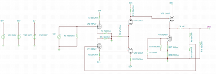
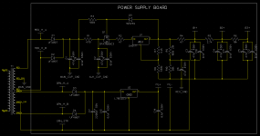
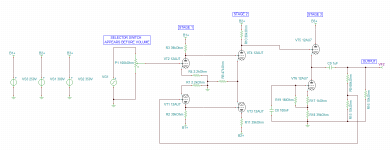
I am building a line stage in a "glass op-amp" type fashion. It has two grounded cathode stages DC coupled to a long tail. The long tail is DC coupled to a current sourced cathode follower. A feedback loop sets the gain. The power supply uses an active regulator. The schematics are attached.
I am having some issues with noise and a selector switch that does not completely isolate the signals. When the switch is in another position, you can hear the music pretty clearly with the volume up. What switches do not do this? On some El-cheapo solid state units I repaired for a client I had the same problem.
I will discuss the noise issues as soon as I am advised on the switch problem. Also, what do you think of the design? It sounds very good. The distortion is low and is very punchy.
Attachments
I am having some issues with noise and a selector switch that does not completely isolate the signals. When the switch is in another position, you can hear the music pretty clearly with the volume up. What switches do not do this?
The problem may not be with the switch. It could be with the wires that go to and from the switch.
The best way to switch signals is to have balanced signals that go to a double pole switch and have the signals in cables that are twisted pair and shielded, grounded on ONE end. Lacking balanced signals you can still use shield cable right up to the switch terminal.
Also never run the cables parallel to each other. They should come to the switch from different angles.
This same applies to EVERY wire in the ampler, do not rn any in parallel, cross them only at right angles and make full use of the 3 dimensional space.
You can test the switch. Get a signal ganerator and place a test tone on one side and check the other with a good, high impedance AC micro voltmeter.
What I'm suggesting is that th signals are jumping over because via the electric fields. So use both eletrocstatic shields on the signal wires and the "inverse square law" (distance).
I am having some issues with noise and a selector switch that does not completely isolate the signals.
The Capacitive coupling between switch contacts/ lines is the
Major problem resulting in CrossTalk.
Suggested solutions: Decrease signal line impedances. Cascade switch
contacts and terminate Off position lines to Ground.
Switch Quality has a relatively minor effect on this coupling.
As suggested by Chris, electric fields are the Major problem.
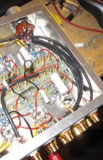
The cables are shielded. The way I have it wired is with shielded two-conductor cable. The black cable carries the left channel signal, the red, the right. The shield is grounded on one end (RCA jack bank). I take it the wires may be too close (see photo).
Attachments
Last edited:
The cables are shielded. The way I have it wired is with shielded two-conductor cable. The black cable carries the left channel signal, the red, the right. The shield is grounded on each end. I take it the wires may be too close (see photo).
Odd that you'd place left and right channles inside the same cable. You will have a worse cross talk problem that way, although your ears will not notice so much.
Also never ground BOTH ends of a shield. That allows current to flow. Only ever ground ONE end only. With one end grounded there is no way current can flow. Avoid ground loops.
One thing you might do is duplicate that resister you have across the input. I think you might be useing one resister after the switch. Better to place the resister directly on each input jack. Now your un-selected leads are terminated .
It does make a difference where physically the resister is. Current flows through that resister and of course in th wires it connects to. Placing it on the input jack keeps the current out of the amp and out of the switch,
Also, the over all grounding plan matters. The input should be ground near the jack, even using non-isolated jacks. Then the signal grounds are star ground and finally the star ground connects to the input jack ground stud. There is also a safety ground near where the AC comes in. All the shields conect to the signal ground one one end only. This way zero current flows in the chassis or the shields.
It seems you posted before I edited. The shields are connected at only one end (the ground of the RCA's.
I do not have resistors across the inputs, just the volume control. Should I place, maybe a 100k on each input jack from signal to ground?
One thing you might do is duplicate that resister you have across the input. I think you might be useing one resister after the switch. Better to place the resister directly on each input jack. Now your un-selected leads are terminated .
I do not have resistors across the inputs, just the volume control. Should I place, maybe a 100k on each input jack from signal to ground?
I do not have resistors across the inputs, just the volume control. Should I place, maybe a 100k on each input jack from signal to ground?
Yes try it. But remove the resistor you have now or else you'd have two in parallel for the selected input.
Placing the resister after the switch allows you to only use one resister but placing it before the switch keep some of the signal out of the switch and the wires. Also your sources will continue to "see" a load when they are unselected.
So you end up with multiple copies of R5. The schematic remains the same. Just that now you mound R5 on the input jack and because you have several jacks you use several resisters but only one is switched in at a time. The unselected ones are just loads for the sources.
Last edited:
Oh, R5 is a volume control. You can't have a 100K resister in parallel with a 100K volume control. It would mess it up. Make the grounding resistors 10X bigger (at least) then the volume control. So use 1M resisters. But maybe even make the pot smaller. The pot in effect determines the input impedance of the preamp. 25K would work. You'd get slightly less thermal noise too.
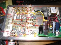
Now to address some of the hum and hiss issues. I tore apart the grounds and signal cables for better wiring.
I labeled a photo for where my various ground points are. The main star point is a solder lug that makes contact with the chassis. Where do you advise I run the ground wires based upon that layout?
The previous layout had a low level hum that changed with the volume. Changing around tubes varied hiss levels. There was some low level buzz that changed with the volume as well. There was a ground loop somewhere because I, while diking around, occasionally had AM radio interference.
I uploaded a revised schematic denoting which stage is which and some other info as well. Note the right channel is not entirely built.
Attachments
Now to address some of the hum and hiss issues. I tore apart the grounds and signal cables for better wiring.....
The firt thing I'd do to address the hum problem is TIGHTLY twist all the AC wires. The mains wires and the heater wires and the transformer leaders. All of these should not show any air gap. Some people will go as far as 8 turns per inch but 4 turns per inch might be fine. The current in each wire cancels the field made by the other wire. If the wires are touching the field is nearly zero at 8 wires diameters distant.
No not coil up and zip tie "extra" AC wire. It needs to be twisted with it's partner and cut short and routed as close to the chassis as can be
Many times DC heaters can be more of a problem then AC. If there is no regulator the recifier noise can be hard to get rid of. A simple lm317 can remove that noise.
Here you can see a spring reverb unit I built. notice the green and yellow heater wire. It is solid #18 wire I twist using a drill motor. I'll make up 10 feet of it at a time. It is about 8 turns per inch. Also all other AC is twisted by the stranded kind just does not hold a tight twist
https://www.dropbox.com/s/nes72pnq0wsbbeg/guts%20angle%20view.jpg
Here is a small 5W guitar amp. The layout is not perfect but I tried to mostly copy the 1950's vintage Fender. All the transformer leads are twisted and as short and direct as possible. All AC wires cross others at 90 degrees angles to minimize contact. Also more of the same green/yellow heater wire I make with the drill and a vice.
https://www.dropbox.com/s/vhj9ykofaodw936/guts.jpg
What seems to matter the most is the last 1/2 inch of wire before the tube sockets. Make sure there are no loops in the AC. Also if the heater wire is stuck to the chassis, flat and the signal wire to the grid comes in like a dive bomber then the two are at 90 degree angle and have minimal coupling
Shields do not work with AC mains and heater wire, the field is magnetic not electric
Route heater wire to output tubes first, then to input tubes. So there is less current in the wires going to the input tubes. Hum does the most harm in the input tubes because it gets amplified more. So if heaters are in parallel the output tube is first in the chain.
Use tube shields. They protect the tubes and hopefully shield out hum and noise.
Finally if you still have hum. Cut the heater leads and hook up some AA batteries. They will power the heaters long enough for a test. Is the hum gone? if so the heaters were the route. If the hum is still there your heater system is good and hum must be in the high voltage system.
Here is Merlin's grounding page. This is best modern practice.
http://www.valvewizard.co.uk/Grounding.pdf
Last edited:
The heaters are all regulated DC (7812 regulator) and elevated to 120 volts. If the heaters are regulated DC, why would hum and wire twisting be an issue?
I also think the zip tied AC Wires are far enough from the small signals to avoid hum inducement, or is this not the issue?
I also think the zip tied AC Wires are far enough from the small signals to avoid hum inducement, or is this not the issue?
My plan is this.
1. Have only a single very short wire run from the main filter cap, transformer center tap, and LM317 ground to a lug. This is the main star point.
2. Revise the regulator board to remove the potential dividers, which will be built point-to-point. Merlin advised there should no long interstage ground wires from the stage ground to the filter cap ground. My existing design violates this rule. Building the potential divider near each amplification stage should correct this fault.
3. Create separate stars for each of the three stages for each channel. I made the unit so both channels share a star.
4. My design uses feedback, so Merlin advised grounding the output jack to the first stage. I did not do this before. I ran it directly to the main star point.
5. Ground each RCA jack in the input bank to the first stage ground. I did this.
6. Run the safety ground through a hum blocking network to the main star point. I did not do this.
Now, here is where Merlin is not so clear. Where should I connect the chassis to the circuit ground? For a single channel unit, he says at the input jack. For multichannel, the point where the channels meet. I am doing stereo, two separate channels. This is not covered.
The heaters are all regulated DC (7812 regulator) and elevated to 120 volts. If the heaters are regulated DC, why would hum and wire twisting be an issue?
I also think the zip tied AC Wires are far enough from the small signals to avoid hum inducement, or is this not the issue?
OK regulated DC is not gong to contribute to hum, still I'd twist them so they don't pick up "whatever" and act as a conduit for it.
AC mains wires are never "far enough away" Certainly if they are inside the same chassis as the signal wire they are very close. Even the wire in the walls of the house cause hum in a high gain amplifier. This is why people use balanced microphone cables, common mode noise is pervasive in the environment. Some people who build preamps for recording (gains is up to abot 65dB) will place the power supply on the floor and still use mu-metal shields on the input transformers. HiFi preamps are not so sensitive but the goal is "no audible hum" is hard to get to unless you do everything you can think of.
The easy way is fully balanced audio. I have yet to make a completely balanced system as the standard for consumer hi fi does not use this.
It would be nice if all consumer equipment, especially turntables, took advantage of balanced topology. I guess they did not for cost reasons.
It would be nice if all consumer equipment, especially turntables, took advantage of balanced topology. I guess they did not for cost reasons.
The easy way is fully balanced audio. I have yet to make a completely balanced system as the standard for consumer hi fi does not use this.
It would be nice if all consumer equipment, especially turntables, took advantage of balanced topology. I guess they did not for cost reasons.
Yes. back in the Tube era the added cost for balanced audio is just about double. You need expensive transformers on both ends of every cable and twice as many tubes and more power and more heat.
This stuff was expensive. The old Hammond organs used in larger size churches were balanced. At the time, one of these larger systems could sell for more than the median price of a house in the US. Quality commercial audio used to be very expensive. But the pro-audio gear has been using balanced connections for at least the last 60 years.
I've always thought at a DIYer should build something he can't buy. Why not take the leads from a phono cartridge and treat them as balanced and keep the concept going all the way through to the power amps? But insted we tend to copy old consumer-level designs.
My next project will be a microphone preamp with in-built optical compressor/limiter. It will have balanced XLR input and outputs and I'd like to maintain a balanced topology inside. I'm only working with breadboard experiment now. I'm looking at the LA-2 compressor as a model
I worked hard at properly re-wiring the unit.
There is still some issues with the volume pot grounding still. There is some faint buzz that disappears when the chassis is touched with the volume up. It is a stereo volume pot. The case of the pot measures 5 ohms between the pot case and the chassis. How should I ground this stereo pot?
Also, I have some radio station interference along with the buzz when AM 1400 is broadcasting during the day. They increase their transmitter power in the morning. Without tube shields, more microphonic tubes pick up AM 1400 clearly audibly when your hand is placed in close proximity. The first stage is the most sensitive to this problem. Is this normal? Can it be remedied?
- Status
- This old topic is closed. If you want to reopen this topic, contact a moderator using the "Report Post" button.
- Home
- Amplifiers
- Tubes / Valves
- Cleaning Up the Noise + Selector Switch Anomalie