Because it makes it better. PSU is not an amplifier circuit or at least it should not take part in it.an electronic regulator is an ss amplifier,
why will i add an ss amp to my tube amp?
I never refuse newer technology if it brings an advantage. I leave the purism to religious people....

Because it makes it better.
a matter of perspective....
a matter of perspective....
Less IMD that has nothing to with the signal is not a perspective. It's a fact.
It's a fact.
oh i won't argue.....just that i do not buy into it...
I'm fully aware of Stephie's work - it was me that linked it, above. But that was the year 1999, and that work has been extended, and - more importantly - corrected subsequently. Dmitry Nizhgorodov performed some useful measurements that showed that the hum products at idle were distortion harmonics of the electrical ac-heat waveform. Dmitry's investigation showed that the hum-harmonics of ac-heat did not diminish sufficiently with frequency of the ac-heating current, to allow a thermal explanation - at higher frequency, the heating-and-cooling cycle becomes shorter, and for a constant thermal mass, the hum-amplitude would decline as frequency rises; but measurements showed that even for 600Hz heating, no decline in hum output was seen.
Dmitry's measurements are here:
On Correlation Between Residual DHT Filament Hum and AC Frequency
This work was performed the collaboration and encouragement of Stephie, and should be taken as superceding the 1999 Bench experiments. Neglecting very lighweight filaments (eg battery triodes), the thermal-variation theory of hum has been completely discredited.
We have to picture the DHT as a Grounded-grid amplifier, to see how this hum-harmonics are generated - with the ac-heat waveform as the (low-impedance) input. The mains fundamental is nulled at idle by the hum-pot, as well as it can be. The nulling is achieved by equalizing the effective ac-amplitude around the centre-tap, where the anode-current is returned to ground. But this null is only valid in the region of the triode curves, near to the operating point; at larger swings, we move into a different curves-region, and the null is lost. In these regions the IMD rises sharply, and shows up easily in a spectrum analyser.
Arguments about ac-heating are perfectly easily settled by simple measurements. Any kind of computer and soundcard is enough to resolve the large amounts of IMD generated by ac-heating, so there is no excuse not to measure.
There are already a number of good assessments posted on our forum, but this one from Bela (euro21 here) shows a direct comparison of ac- and dc- heating of 300Bs (5V, as per the type 71A in the OP's question).
http://www.diyaudio.com/forums/tubes-valves/258870-sound-300b-set-satoru-kobayashi.html#post4030013
The power output in these plots is only 1W, but the ac-heated PP sample (the RIGHT-hand picture) is already generating large numbers of sidebands - the mains-fundamental sidebands (±50Hz in this case) are only 50dB down. Keep in mind that these sidebands will arise around every tone in the music, creating a widespread fog across the spectrum (a fog is rather like what it sounds like, too). This is certainly not my idea of Hi-fi.
Thanks. I've read Dmitry's contribution, but need to refresh my memory about it.
AJT what was the purpose of your intial question? I am sorry if you didn't like the response but that is. If you think that SS should not have a place in your amps then why bother? You just live with that limitation without aguing.
i am just asserting my right not to use regulators in my amp, in your amp
you are perfectly within your right to use them if it pleases you....
technical superiority notwithstanding....
how to enjoy your music is not a matter for argumentation....imho...
i am just asserting my right not to use regulators in my amp, in your amp
you are perfectly within your right to use them if it pleases you....
technical superiority notwithstanding....
how to enjoy your music is not a matter for argumentation....imho...
I am not questioning your rights and your opinion. I just don't understand why you asked me. I told you that it is not just technical but then you concluded that you are not interested because you don't like SS in your amps. I cannot see the logic, sorry. Never mind.....
I'm fully aware of Stephie's work - it was me that linked it, above. But that was the year 1999, and that work has been extended, and - more importantly - corrected subsequently. Dmitry Nizhgorodov performed some useful measurements that showed that the hum products at idle were distortion harmonics of the electrical ac-heat waveform. Dmitry's investigation showed that the hum-harmonics of ac-heat did not diminish sufficiently with frequency of the ac-heating current, to allow a thermal explanation - at higher frequency, the heating-and-cooling cycle becomes shorter, and for a constant thermal mass, the hum-amplitude would decline as frequency rises; but measurements showed that even for 600Hz heating, no decline in hum output was seen.
Dmitry's measurements are here:
On Correlation Between Residual DHT Filament Hum and AC Frequency
This work was performed the collaboration and encouragement of Stephie, and should be taken as superceding the 1999 Bench experiments. Neglecting very lighweight filaments (eg battery triodes), the thermal-variation theory of hum has been completely discredited.
We have to picture the DHT as a Grounded-grid amplifier, to see how this hum-harmonics are generated - with the ac-heat waveform as the (low-impedance) input. The mains fundamental is nulled at idle by the hum-pot, as well as it can be. The nulling is achieved by equalizing the effective ac-amplitude around the centre-tap, where the anode-current is returned to ground. But this null is only valid in the region of the triode curves, near to the operating point; at larger swings, we move into a different curves-region, and the null is lost. In these regions the IMD rises sharply, and shows up easily in a spectrum analyser.
Yes, Dmitry's work convincingly demonstrates that residual heater noise is the amplified second harmonic of heater voltage, and not thermal modulation. But it doesn't say anything about IMD distortion.
Arguments about ac-heating are perfectly easily settled by simple measurements. Any kind of computer and soundcard is enough to resolve the large amounts of IMD generated by ac-heating, so there is no excuse not to measure.
There are already a number of good assessments posted on our forum, but this one from Bela (euro21 here) shows a direct comparison of ac- and dc- heating of 300Bs (5V, as per the type 71A in the OP's question).
http://www.diyaudio.com/forums/tubes-valves/258870-sound-300b-set-satoru-kobayashi.html#post4030013
The power output in these plots is only 1W, but the ac-heated PP sample (the RIGHT-hand picture) is already generating large numbers of sidebands - the mains-fundamental sidebands (±50Hz in this case) are only 50dB down. Keep in mind that these sidebands will arise around every tone in the music, creating a widespread fog across the spectrum (a fog is rather like what it sounds like, too). This is certainly not my idea of Hi-fi.
I looked at it, and it is not convincing. First, why comparing apples to oranges (I mean PP and SE amps)? Second, in both graphs there is a lot of noise from AC and its harmonics, not necessarily coming from the heaters. Third, what you believe to be 50 Hz IMD in the PP graph looks to me like noise.
Last edited:
Yes, Dmitry's work convincingly demonstrates that residual heater noise is the amplified second harmonic of heater voltage, and not thermal modulation. But it doesn't say anything about IMD distortion.
Dispensing with thermal theory of hum is essential to clear the way to explain the mechanisms of hum (at idle) and IMD as electrical input. Dmitry also confirms the expected result that dc heating yields no hum components. Now we can explain the outcome of both hum and IMD as the uncancelled components of grounded-grid amplification.
If you are not satisfied with this explanation, you can confirm it easily enough.
0. Obtain Triode curves for your DHTs.
1. Draw a load-line for your own DHT amplifier on the triode curves.
2. At different points on the load-line, draw vectors for grounded-grid input: a Vgk and Vak combined vector.
3. The input amplitude will be 0.5 x (peak heat waveform): So for 300B (5V heat) it will be 2 x 1.414 x 5 = ~3.5V
4. The peak output current represents the scale of the effect at the physical ends of the filament, so the total output will be lower, overall.
5. it is also obvious from this exercise that the nulling of the hum at idle cannot null the IMD vector at large swings, especially with a reactive (speaker) load, where the load-line opens out into an ellipse. For this to be accurate the triode curves must be real, and not simplified, as some data sheets draw them. There are quite a few traced curves available for different valves. Ale Moglia has traced some useful DHT types.
I looked at it, and it is not convincing. First, why comparing apples to oranges (I mean PP and SE amps)? Second, in both graphs there is a lot of noise from AC and its harmonics, not necessarily coming from the heaters. Third, what you believe to be 50 Hz IMD in the PP graph looks to me like noise.
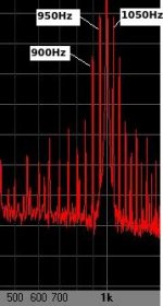
Well PP is very unlikely to make the ac-heated example perform worse. It is perfectly clear to me that the 1KHz signal has -50dB spurs at 950 and 1050Hz. Are you viewing on a small screen?
I have taken the liberty of taking a detail of Bela's FFT to expand and highlight the 1KHz sidebands.
But if you are not satisfied, what is stopping you from measuring it and doing the ac & dc comparison yourself?
Attachments
If you are not satisfied with this explanation, you can confirm it easily enough.
0. Obtain Triode curves for your DHTs.
1. Draw a load-line for your own DHT amplifier on the triode curves.
2. At different points on the load-line, draw vectors for grounded-grid input: a Vgk and Vak combined vector.
3. The input amplitude will be 0.5 x (peak heat waveform): So for 300B (5V heat) it will be 2 x 1.414 x 5 = ~3.5V
4. The peak output current represents the scale of the effect at the physical ends of the filament, so the total output will be lower, overall.
5. it is also obvious from this exercise that the nulling of the hum at idle cannot null the IMD vector at large swings, especially with a reactive (speaker) load, where the load-line opens out into an ellipse. For this to be accurate the triode curves must be real, and not simplified, as some data sheets draw them. There are quite a few traced curves available for different valves. Ale Moglia has traced some useful DHT types.
You are substituting the issue. The argument wasn't about whether or not AC-heated DHT have residual hum. The real issue was IMD caused by filament hum under conditions of low harmonic distortion.
Well PP is very unlikely to make the ac-heated example perform worse. It is perfectly clear to me that the 1KHz signal has -50dB spurs at 950 and 1050Hz. Are you viewing on a small screen?
I have taken the liberty of taking a detail of Bela's FFT to expand and highlight the 1KHz sidebands.
Well, may be or may be not. PP data are particularly suspicious because, at least in theory, PP should be largely free of residual hum, as it cancels the 2nd harmonic. Then, how come 50 and 100 Hz fundamentals are lower than 1050 and 1100 IMD signals? Something doesn't match here. I tried to copy and paste the graph to expand it on the x axis, but it didn't work. Looking carefully, there are additional closely spaced bands in the vicinity of the 1 kHz band. Provided that this is a screenshot, it is a plausible proposition that this is noise.
But if you are not satisfied, what is stopping you from measuring it and doing the ac & dc comparison yourself?
I have determined for myself that AC filaments in a 2A3 PP amp do not cause audible IMD. From Steve's paper, IMD from residual filament hum with 6.3 VAC filament voltage is about 0.12% at moderate amplifier power. For 2A3 or 4P1L it should be 0.04-0.05%.
The real issue is whether filament-borne IMD is any different from IMD caused by complexity of musical signal. I am thinking of something like 6A3 stage, with filament fed by either AC, or DC from a lead battery. Apply a mixture of 400 Hz and 1000 Hz to input and measure 600 Hz and 1400 Hz at the output, then compare the levels to filament-borne IMD. Need to buy spectrum analyzer software.
This has all been known since the 1920s (and possibly before).
Read The Thermionic Vacuum Tube Physics and Electronics by H.J. Van Der Bijl.
That's a big book. What particular chapters you are referring to?
I use Rod's regulators in my 71A Parallel Feed Headphone amp prototype and am quite satisfied.
Please note that in no way I am trying to bash Rod's regulators. In your application DC regulators are totally justified.
I did a more relevant test myself. The A4 piano sound (440 Hz fundamental) was picked up by a high quality condenser microphone and amplified by a PP tube amplifier whose driver (26) and output (2A3) tubes were AC-heated. The speaker and the piano were in different rooms. I asked my daughter (a trained musician and piano tech) lo listen to the amplified sound for the presence of IMD tones with ±60 and 120 Hz, which would be approximately C5, B4, G4, and E4. She couldn't detect any.
Has your daughter absolute pitch?
I have determined for myself that AC filaments in a 2A3 PP amp do not cause audible IMD.
Can you please post your measurements?
From Steve's paper, IMD from residual filament hum with 6.3 VAC filament voltage is about 0.12% at moderate amplifier power. For 2A3 or 4P1L it should be 0.04-0.05%.
Just out of curiosity, how did you find those numbers?
Can you please post some more detailed calculations?
Last edited:
Has your daughter absolute pitch?
Probably more than that. She never uses tuning fork or any other reference sound in her work. She claims she can hear inharmonicity in piano sounds.
Can you please post your measurements?
There were no measurements. I said there was no IMD audible to a trained musician.
Just out of curiosity, how did you find those numbers?
Can you please post some more detailed calculations?
Please look at Steve's paper here:
Effects of AC Heating Power Applied to Directly Heated Triodes
The IMD table is at the end of the article. The data are for DHT with 6.3 V filament. For 2.5 V and 2.1 V filaments, hum values and IMD should be proportionally less.
Probably more than that. She never uses tuning fork or any other reference sound in her work. She claims she can hear inharmonicity in piano sounds.
Amazing! Congratulations to her!
There were no measurements. I said there was no IMD audible to a trained musician.
OK, so far we must trust in your words and your daughter's ears.
Please look at Steve's paper here:
Effects of AC Heating Power Applied to Directly Heated Triodes
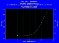
The IMD table is at the end of the article. The data are for DHT with 6.3 V filament. For 2.5 V and 2.1 V filaments, hum values and IMD should be proportionally less.
Sorry, the law of proportionality is not evident, but it is not linear for sure, actually raw data fit reasonably well with a Gaussian.
Then, your numbers are meaningless.
Rod's effort to explain us a phenomenon deserves at least some measurements and calculations.
Attachments
Last edited:
You are substituting the issue. The argument wasn't about whether or not AC-heated DHT have residual hum. The real issue was IMD caused by filament hum under conditions of low harmonic distortion.
There is no need to restrict our view to a narrow range of conditions. The mechanism by which filament-supply hum and filament-supply IMD arise are the same thing: Grounded-grid ampification of a large, and imperfectly-nulled input waveform. I have given a full explanation, which you can confirm or deny to your own satisfaction - But - please excuse those of us who will not accept anecdotal accounts, informal listening tests or interpretive examination of dusty old reports as a substitute for real measurements and analysis.
Clinging to the near-20-year-old Bench write-up is leading you astray. It is based upon speculation that thermal variation causes hum. The theory was bogus, and so the whole write-up is dubious.
The lab bench is where theory, calculations and computer-simulations meet their Ruler, as Jim Williams puts it.
OK, so far we must trust in your words and your daughter's ears.
Sorry, the law of proportionality is not evident, but it is not linear for sure, actually raw data fit reasonably well with a Gaussian.
Then, your numbers are meaningless.
Rod's effort to explain us a phenomenon deserves at least some measurements and calculations.
Hi Popilin! Thank you - yes, I agree - and the measurements are not difficult to take.
Hi Popilin! Thank you - yes, I agree - and the measurements are not difficult to take.
Hi Rod! On the contrary thank you!
You have explained the phenomenon better than any textbook, even more, you have teached us the best way to avoid it.
Nevertheless, warn you that in a time that people use computers and smartphones daily, a big number of them still believe that AC in the heaters is the best.
We have a saying here: There is no deaf worse than he who will not listen.
- Status
- This old topic is closed. If you want to reopen this topic, contact a moderator using the "Report Post" button.
- Home
- Amplifiers
- Tubes / Valves
- 71A Tube Filament: AC or DC ?