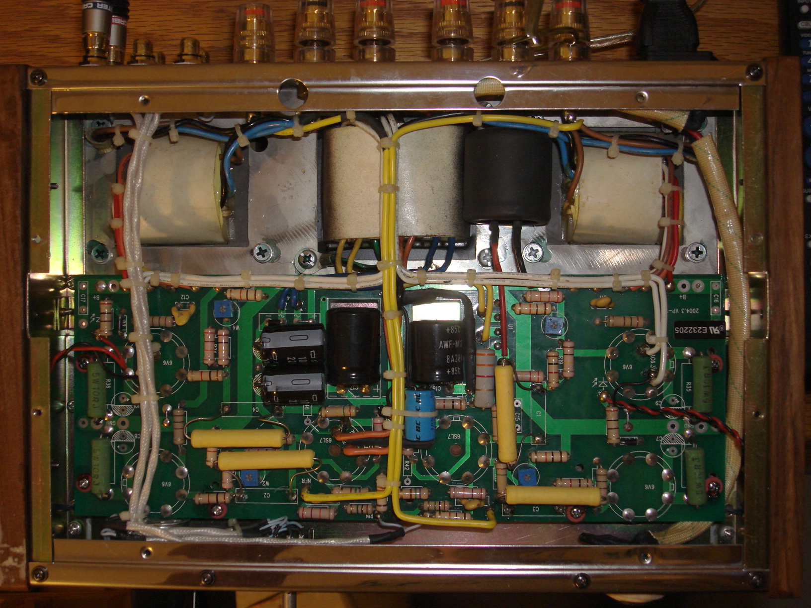
I have a 2x6SL7 4x6V6 push pull amp, Dared VP-16, and the voltage over a fixed resistive load sinks with frequency. For 5 ohm, with low audible output through the other channel, it began with 0.5 V and it sank evenly to 0 V at 20k Hz, a 20 Hz to 20k Hz sine sweep. This is read from a multimeter. Perhaps it assumes a 60 Hz signal, I don't know. The amp sounds a bit dark, but not as much as these figures suggest. Is this something any of you can help me with? I can upload a photo of the circuit board, if that helps.
Last edited:
More then likely it's poor response from your multimeter. Can you be very specific regarding the make and model number. If it's a garden variety digital, or even analogue meter, (rat shack, harbor freight & the like) they don't read well past several hundred cycles. You need a purpose designed wideband AC voltmeter for doing audio sweeps.This is read from a multimeter. Perhaps it assumes a 60 Hz signal, I don't know.
A schemo of the circuit would be better than a piccie of the circuit board. An o'scope would be better than a multimeter. Most multimeters are designed to operate at typical line frequencies (50, 60Hz -- some to 400Hz aircraft line AC) not audio frequencies.
Does this design include gNFB? If it sounds a bit dark, this could be due to excessive gNFB. That's what I got when employing too much gNFB with my designs.
Does this design include gNFB? If it sounds a bit dark, this could be due to excessive gNFB. That's what I got when employing too much gNFB with my designs.
http://www.diyaudio.com/forums/atta...037357-rasping-sound-dared-vp-16-dsc08404.jpg
The better multimeter is a CEN-TECH P3772 which reads Hz. AC 40 Hz to 400 Hz. I know nothing about tube amps.
The better multimeter is a CEN-TECH P3772 which reads Hz. AC 40 Hz to 400 Hz. I know nothing about tube amps.
Last edited:
... This is read from a multimeter. Perhaps it assumes a 60 Hz signal, I don't know. The amp sounds a bit dark, but not as much as these figures suggest. Is this something any of you can help me with? I can upload a photo of the circuit board, if that helps.[/QUOTE]
Unless the meter is special made for higher frequencies it will read just as you observe red there are two things you can do:
1) build a good AC to DC converter and then measure the DC from that. Basically all need is a good switching diode and a good capacitor and a high value resister. Better ones that are good to say 1% error on small signals needs a couple op amps and one more diode. But the simple and cheap passive device can work
2) If you have an audio input on your computer you can measure the voltage across your load resister with the computer. You will liley have to scale the rage so it only goes up to 1 volt. You can't do absolute measurements but you only need relative valiues. These measurements can be very good and detailed. Use the output side of the audio interface as a tone generator to drive the amp. You can do frequency sweeps and measure the responses. First verify your system by using a wire in place of the amp. You can also, with the right FFT software measure harmonic distortion and just about "anything".
3) I ave an old vacuum tune AC meter that goes up to 300KHz and is calibrated in dB. These are very easy to use and available on eBay for not a lot.
The computer interface is best best bet, software can be free.
I have found digital volt meters, specifically Sears 82140, can't read music frequencies, only 50-60 hz.
I have found my Simpson 260 Analog meter (200 kohm/volt) reads music quite well on the 20 VAC scale on the speaker outputs of my ST70 amp. That is when everything is new in the amp (tubes, e-caps) and B+ is reading right, I can get 17.5 VAC peaks on the 8 ohm taps. As a result, you can't buy a Simpson 260 anymore, it is "obsolete". You could buy the Sears 82140 over several years at any of 1500 outlets across the nation.
The Simpson VTVM somebody gave me, a 60's relic, also reads AC music with the "RF probe" a capacitor in series with the input in a little plastic shell. (I put the capacitor in series with the 260 on AC scales with clip leads. Smaller capacitors can detect RF oscillations instead of music).
This response curve thing is important to people who recap the tone generator on Hammond B/C3 organs. The output curve must be set flat so the 84 tones sound the same. The only guy who got a decent response from his DVM, had some cheap Ch***** brand DVM that you can't buy the same thing again anywhere. The Fluke manual for their RMS reading meter doesn't address the frequency response issue.
Scopes break 2 weeks after you buy them, unless you buy new IMHO. The last one I bought, the boards were glued in where you couldn't change the electrolytic capacitors without breaking the control rods.
Last edited:
The problem resolved itself when I put in the original c1-c4 caps. The paper in oil sounded a bit dark. Thank you for your help. I also did try bigger caps than the original but the sound was about the same. 0.22 uF vs 0.60 uf. The photo wasn't totally accurate because the original and the paper in oil were in series, a futile attempt at lowering the voltage and extending the life of the tubes. 0.11 uF vs 0.22 uF stock. When alone the paper in oil also were dark-sounding.
The sound was a bit more powerful with 0.60 uF but I'm afraid the rest of the design could suffer. I wish I knew more about this. Is there a good book for a beginner on tubes?
The sound was a bit more powerful with 0.60 uF but I'm afraid the rest of the design could suffer. I wish I knew more about this. Is there a good book for a beginner on tubes?
This Tube Amplifier Debugging Page has been useful to me for repairing tube amps. Designing tube amps, I dis-reccommend RCA Radiotron Handbook 1961 edition and Electronics for Scientists, 1968 edition. Wikipedia is better. There is another book people recommend here but I never bought it. There are some free old textbooks available for download at Technical books online
- Status
- This old topic is closed. If you want to reopen this topic, contact a moderator using the "Report Post" button.
- Home
- Amplifiers
- Tubes / Valves
- Weak treble