My favorite is the Fairchild FPQ1N50 - no longer in production, but I have a stash for purposes like this. It also has low input and reverse transfer capacitance, lower than the IR part Eli mentioned. The Zetex part he mentioned is attractive, but is limited in practical power dissipation to ~1/2 W, unless you glue on a heat sink. I got another part from IXYS when the Fairchild part dried up - a 2A, 600V part. It's not as good as the Fairchild (Crss is good, but Ciss is a bit high at 240 pF).
I haven't been looking lately, as I still have some of the Fairchild parts, but Alpha and Omega is a good vendor of advanced mosfets, and Digikey stocks a fair number of them. It's a good idea to look first at the smallest current parts for a given voltage rating, to keep the die size (and associated capacitance) to a minimum.
Edit - The Alpha Omega part AOT1N60 is better (much) than even the Fairchild part - maybe I'll get me some...
Last edited:
....more than whats drawn to correct that too.
not sure what drawing...?
Attachments
What drawing? #13...
As for #68, Driving impedance is not equal without 1/Mu cathode feedback
from the drain, to mimic the effect Mu has upon the top side impedance...
But we also know in the context of driven loads that are equal, and a closed
loop: Locally "equal" driving impedance isn't critical to class AB1 operation.
Primitive concertinas that operate half blind certainly do work. Caves or not.
Even the blind side isn't totally blind, once the GNF loop is closed.
The plate load for the second stage should be across VGS, as that gives you
a constant current source essentially for free.
If you choose to do neither, then there is no advantage to the P-CH splitter.
You would have a better choice of easily obtainable MOSFETs in N-CH...
Last edited:
The Zetex part he mentioned is attractive, but is limited in practical power dissipation to ~1/2 W, unless you glue on a heat sink.
Mouser stocks 2 parts that might be worth a tumble: 532-322400B00 and 532-575200B00.
I don't like those clip-on heat sinks - I find them flimsy and unreliable. I just glue a piece of aluminum to the package with Arctic Silver epoxy. I suspect that even JB Weld would work as adhesive for a high thermal resistance application like this, as it's metal filled.
I don't like those clip-on heat sinks - I find them flimsy and unreliable. I just glue a piece of aluminum to the package with Arctic Silver epoxy. I suspect that even JB Weld would work as adhesive for a high thermal resistance application like this, as it's metal filled.
Do you bother to blacken the aluminum pieces that you use?
We really need a fully differential phase splitter that can drive DC into grids.
Impedances both so ridiculously low it won't matter if they equal or not...
Something like the concept shown in #41, but with more details worked out.
Fully differential op-amps are certainly available, but thats sorta cheating....
Impedances both so ridiculously low it won't matter if they equal or not...
Something like the concept shown in #41, but with more details worked out.
Fully differential op-amps are certainly available, but thats sorta cheating....
What drawing? #13...
good one, thanks
As for #68.....
I was sleepy and on my way to bed
 so I have to repost it
 maybe Im clueless already, but what you guys consider optimal in the end, will probably be out of my reach anyway
Attachments
I'm just sayin' if you not gonna leverage any advantage offered by P,
you would be better served with N, superior in every other respect.
Plain old concertina will work fine with either type...
No, wait... You are using a unique feature of P, I just didn't see it...
If plate is comfortably above B/2, then you can direct couple just
as you've drawn. With N would have to do something more to drop
the coupling voltage below B/2. Maybe this advantage makes P
worth its weight even in this most simplified circuit?
-----
So, thats 3 advantages for P.
1) Direct coupling at 3/4 B+
2) Free CCS by strapping plate resistor across VBE or VGS
3) Equal impedance split, if we feed Drain/Mu back to Cathode
Advantages for N.
1) Works in traditional circuit without modifications
2) Better gm and less capacitance than P
3) Cheap and plentiful
Last edited:
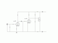
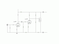
ehh...what  did I accidentally turn the ZVN0545 mosfet upside down ?
btw, I tried to find a mosfet equal to the suggested ZVN0545, on capacitance parameters
but seems impossible to beat
output and reverse capacitance might be matched by a few others, but input capacitance will be higher
btw, I tried to find a mosfet equal to the suggested ZVN0545, on capacitance parameters
but seems impossible to beat
output and reverse capacitance might be matched by a few others, but input capacitance will be higher
Yeah, that symbol is drawn a bit weird.
Channel arrow looks like N, but gate connection oriented like P.
Suppose I should still have read that as N, just tripped me up.
If thats really a symbol for N? You probably can't direct couple.
Unless you gonna run the plate at some crazy low voltage...
Would have to be below 1/2 B+, would not recommend.
Maybe i nitpick over nothing. Usual direct coupling is 1/3 B+.
With the other 2/3 devoted to the plate resistor, or plate and
cathode resistors. It works just fine, and always has..
I suggest the higher plate voltage offered by P, at 3/4 B+.
Resistor across VGS holding the plate at constant current.
Will find almost 1/2 B+ headroom either end can swing...
I don't know whats the headroom on the old way? Has to
be a lot less than 1/3, to leave something for the plate...
Last edited:
- Status
- This old topic is closed. If you want to reopen this topic, contact a moderator using the "Report Post" button.
- Home
- Amplifiers
- Tubes / Valves
- SS phase splitters?

