... so I have a bunch of these nice "super" 6BG6-GA (7027A in disguise) gathering dust, just burning for me to build a nice amplifier around them.
For this design, I want to try zero global feedback, which means extracting the maximum performance from the output configuration & local feedback. Distortion trumps power, but I'd still like to get reasonable efficiency. Triode class AB2 is one option, but I'm thinking I would rather run ultra-linear, with a separate screen winding to allow a higher B+ on the plates, and another separate winding for cathode feedback. Having not tried the latter before, and wanting to 'get it right' (or close to right) with a set of custom-wound OPTs, all sorts of questions about distributed load winding ratios come to mind…
For a start, the optimal Pentode loading appears to be 6.6k, which SY also suggests is a good loading for Triode strapped operation. One might then assume then that this would also be a good load for UL operation - would that be a correct statement?
Second, I'm having a hard time figuring out the optimal UL% to use. I am presently reading R. Moers' article on calculating the optimal UL%, but it seems that 43% is commonly recommended by the original manufacturers for this broad family of valves, apparently on the vague premise that about 25% gives most of the distortion reduction, but there is more to gain with yet more screen feedback. I am also uncertain how the screen FB would be affected, if at all, by running a separate winding at a lower DC potential than the plates.
Third, I haven't yet decided how much winding to put under the cathodes. What Crowhurst calls "modified ultra-linear" subtracts the full UL percentage from the primary and places it in the cathode winding, such that the screens simply tie straight to a regulated supply. This achieves the maximum cathode feedback without reversing the polarity of the screen drive (and neatly eliminates one winding), but at a typical UL ratio of 43%, it demands an awful lot of voltage from the driver stage. Drive swing and heater breakdown considerations may set a practical upper bound, but I wonder if there is an optimization / distortion null (maybe an IMD minima?) to be obtained by choosing the right ratio of cathodes to screen winding, or if the benefit of the larger 43% vs. a lesser UL% is largely wasted, unnecessarily burdening the drive stage? I note that the Quad II apparently uses only a 10% winding at the cathode.
Finally, in some distributed load implementations (MacIntosh, etc.), I have seen the appearance of an extra small-value choke at the plates of the output tubes, and I'm curious as to the purpose of this. Stability? Reduced IMD?
Between plate load impedance, bias point, plate & screen supply voltages, screen winding % and cathode winding %, I don't think I could possibly explore the universe of possible solutions on my own. I'll keep reading as much reference material as I can lay my hands on, but I'm hoping the resident experts will come out of the woodwork and help guide me towards a good configuration for some custom OPTs.
43% of voltage (hence also number of turns) has been the accepted "standard" for Ultralinear taps. If you go back and start researching the beginnings of Ultralinear you will find that 43% is the optimum minum distortion configuration for EL34 tubes (20% for max power). Also appropriate for EL84. Once you start talking about other tubes then other ratios actually apply but since these are hardly ever documanted folks just assume that 43% will suit every tube.
An old paper by Fritz Langford Smith (Editor of Radiotron Designers Handbook) suggests 5 to 10% is what best suits 6V6. I have seen seen at least one KT88 amp which used 50% taps.
Next you state you want to combine cathode feedback and ultralinear. The thing to recognize here is that the Ultralinear feedback is the voltage applied between screen and cathode. If you apply 10% NEGATIVE cathode feedback then the ultralinear taps will want to be around 30% to give you the same Ultralinear operation as 10 + 30 = 40%.
If you look at Plitron VDV2100 CFB/H Torroidal Output Trannies (for example) you will see that it offeres exactly this, 10% cathode feedback windings with UL taps at 30%.
They also have a 2100-SSCR which is 40% Ultralinear in a separate winding.
There are a few weird arrangements around, probably the weirdest is the Jadis JA80 (4 x KT88 in Class A for 80 Watts) which uses about 50% Ultralinear with 10% POSITIVE cathode feedback to arive back at the approximately 40% point again.
If you want the Fritz Langford Smith articles (From Radiotronics Magazine) send me a PM. They would be too big to post here (approx 500KB). They were in 3 parts, a quick google of "Radiotronics Ultralinear" suggested that a couple of the parts may be available on some sites.
Cheers,
Ian
Last edited:
Thanks Ian,
I'll send you a PM about the paper - I may already have it, but if not I would definitely like a copy. Over the years I've been collecting papers on Ultra-Linear / Distributed Loading from around the web. The two best sources I've found recently are the Pearl Audio archive and this page.
I still need to digest some of these articles, but I think I have the basic winding rules figured out... To summarize: cathode winding + plate winding are in series driving the load, so whatever percentage winding is used at the cathode must be subtracted from the plate winding in order that the tube sees the same total load impedance. The cathode winding will also subtract voltage from Vg2-k, so the cathode winding percentage should also be subtracted from the UL tap or winding, as you note. However the screen grid does not really participate in driving the load, and so the percentage selected for the screen connection does not really affect the other windings.
Where I could use some help is in the optimization...
Giving my last post a bit more thought, let me try and be a bit more methodical than just posting a laundry list of questions... I'll start with the most essential one: does anyone have any data or experience on what the optimum UL ratio is for the 7027A / super-6BG6 is?
I may need to go make some measurements to figure that out, though I don't have all the bits 'n bobs needed to do that just yet. It seems to me that once the basic tube characteristic is linearized with g2 feedback, then any other feedback applied (including cathode feedback) will simply reduce distortion further. So I suspect if I can get the UL ratio tuned well first, then deciding what cathode feedback ratio to use will be a much simpler matter, provided there isn't some hidden gotcha or overlooked advantage lurking.
As suggested here:
http://www.diyaudio.com/forums/tubes-valves/234964-best-pp-opt-30-100w-range-2.html
the OPT you want is not going to be cheap. Tertiary windings require quite some additional work and re-design but I think they are worth the price and represent the best solution even if you had tubes which usually do not require lower G2 voltage.
For cathode feedback you can ask for 10%. This should be enough to drastically reduce plate resistance even in pentode/tetrode connection. The amount of dB's depends on the tube and operations. However it should be in the range between 6 and 12 dB.
Thanks 45.
I know the OPTs won't be cheap, but I consider it a good place to put the budget saved by going with an oddball NOS tube instead of the high-demand / high-dollar audiophile stuff (300B, KT88, etc.). I think the investment is worthwhile - a good OPT and output tube are the foundation of the amplifier ... the preceding stages and power supply circuits can be changed around at relatively little expense.
10% sounds like a sensible value for the CFB windings.
I'm now reading the "Adjustable distributed load discussion" thread, so maybe I'll decide to try and measure my tubes with a transformer on hand, in the search for that optimal UL ratio.
-----
Anyone have any insights into the little plate chokes?
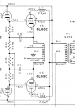
See attached schematic of the McIntosh MC40 output stage, which shows 2.2uF chokes. Strictly for stability, or is there more to it?
I know the OPTs won't be cheap, but I consider it a good place to put the budget saved by going with an oddball NOS tube instead of the high-demand / high-dollar audiophile stuff (300B, KT88, etc.). I think the investment is worthwhile - a good OPT and output tube are the foundation of the amplifier ... the preceding stages and power supply circuits can be changed around at relatively little expense.
10% sounds like a sensible value for the CFB windings.
I'm now reading the "Adjustable distributed load discussion" thread, so maybe I'll decide to try and measure my tubes with a transformer on hand, in the search for that optimal UL ratio.
-----
Anyone have any insights into the little plate chokes?
See attached schematic of the McIntosh MC40 output stage, which shows 2.2uF chokes. Strictly for stability, or is there more to it?
Attachments
CFB works best with high prevalence, high Mu tubes. It is a complete waste to use CFB with low to medium Mu triodes. The point of diminishing returns (required driver vs. lowered Rp) falls between 10% to 15% for most pentodes. You can go upwards to 20% with low prevalence, low amplification pentodes. However, your drive requirements can get ridiculous pretty quick if you don't think things through. I love CFB with high prevalence sweep pentodes. For example, a 6JG6 with 15% CFB basically becomes a triode with an Rp of 640 ohms and a Mu of 6.3
Chad: first the chokes, I'm pretty sure that their reason for existence, being so small in value, is to control spurious oscillations and/or HF ringing, and not fundamentally part of the architecture of the Mac.
I've been conducting lots of simulations and analysis of different kinds of beam pentodes and have come to the conclusion that there is a first order relationship between the optimum plate/G2 "swing" ratio and the ratio between of the gm between G1 and G2. You have already found in the literature from the Golden days that the 43% (impedance, mind you, not voltage ratio! i would prefer these stated in terms of voltage ratio as being far more useful in analysis) number is far from universal. Sweep tubes, for example, have a very high gm for G2 and intuitively I would assume them to want a lower ratio of G2 swing vs plate swing because of the far greater effect on plate current that G2 swing has.
Good luck, I'll be watching posts here, very interesting!
Rene
When one says 10% CFB, is this 10% of the anode voltage and thus 10% of the primary turns?
The Langford-Smith articles are on the Pearl web site.
It is a percentage of the primary turns, thus a voltage ratio. If we are talking about a SE transformer, then there is an extra tertiary winding that has X% of the whole primary turns. With PP transformers, there is normally a center tapped tertiary winding that is X% of the whole primary winding.
Last edited:
It easy in our minds to expect too much of an "optimum percentage" for the screen taps. Each of the functions, distortion, output impedance, and power output, changes monotonically. There really isn't some "optimum" general choice.
As far as the McIntosh amplifier, those small chokes are for parasitic suppression. The output valves are biased almost off, so will try to excite primary resonances regularly during the duty cycle. The other polarity valve's cathode winding is bifilarly coupled, so helps to damp this, but no coupling is perfect, especially anode to anode.
All good fortune,
Chris

Anyone have any insights into the little plate chokes?
See attached schematic of the McIntosh MC40 output stage, which shows 2.2uF chokes. Strictly for stability, or is there more to it?
Take a look at Miles Prower's Vixen where he uses similar chokes, and describes how to wind them, and why he uses them, on 807s (forerunner to 6L6 family, including 7027a)
Thanks everyone for the replies. I'm now immersed in even more reading... I still see conflicting reports on whether an optimal UL feedback percentage exists or not.
Chris - you may be right, that the functions all vary monotonically. I think it would be rather nice if true, as it would simplify the design / decision process considerably. I'm curious what has lead you to this conclusion.
For the moment (having not digested all the literature nor made any measurements), I'm inclined to believe that there is indeed a "best" UL ratio, unique for each tube type (or maybe a "best compromise" according to the designer's preference - lowest THD, lowest high-order HD, lowest IMD, etc.). Considering that the response to screen grid drive is known to be slightly non-linear, and the same can be said of control grid drive (otherwise we wouldn't be trying to improve it!), it seems plausible then, that the control and screen grid non-linearities could conceivably achieve partial cancellation at some particular ratio. I've read somewhere (now I can't remember which paper!) that cancellation of particular harmonics can be achieved by adjusting the UL ratio.
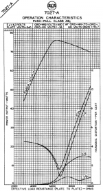
Where this all gets rather complicated and messy – to the point of making me wonder if a big investigation into this would be worth the return on effort – seems to be that a given tube's distortion profile will change depending on load impedance and operating point. This is clearly shown in some tube datasheets, which show curves of distortion vs. load impedance. Here, for example is the 7027A datasheet chart for power and distortion vs. load, at a given PP operating point. Further, there is the consideration of how the distortion changes with power level - perhaps at, say, 1W of output, the optimal ratio is different from 35W, and what the datasheet curve shows is really at the edge of the power envelope, where the output stage is skirting the edge of clipping behaviour (in which case this curve is perhaps a lot less meaningful than a 1W curve).
JLH:
The drive requirements do indeed get a bit silly with excessive CFB. Interesting comment about perveance - makes sense. What, in your estimation, counts as a "high perveance" tube (it's not a commonly listed spec)? Pretty much all the usual 6L6-oid power pentodes? Just looking at transconductance as a stand-in, I see the 6550 and EL34 look to be roughly double the gm (and appear to have larger cathode areas) of the 7027A.
prairieboy:
Thanks for the tip on Vixen. Unfortunately, having tried to search, I haven't yet turned up the description regarding plate choke purpose and winding method that you mentioned. It seems Mr. Prower is a rather prolific poster... my searches have either turned up nearly nothing, or hundreds of results! If possible, could you point me to the specific thread / site? ... or in lieu of that, a synopsis of the salient points would be nice.
Chris - you may be right, that the functions all vary monotonically. I think it would be rather nice if true, as it would simplify the design / decision process considerably. I'm curious what has lead you to this conclusion.
For the moment (having not digested all the literature nor made any measurements), I'm inclined to believe that there is indeed a "best" UL ratio, unique for each tube type (or maybe a "best compromise" according to the designer's preference - lowest THD, lowest high-order HD, lowest IMD, etc.). Considering that the response to screen grid drive is known to be slightly non-linear, and the same can be said of control grid drive (otherwise we wouldn't be trying to improve it!), it seems plausible then, that the control and screen grid non-linearities could conceivably achieve partial cancellation at some particular ratio. I've read somewhere (now I can't remember which paper!) that cancellation of particular harmonics can be achieved by adjusting the UL ratio.
Where this all gets rather complicated and messy – to the point of making me wonder if a big investigation into this would be worth the return on effort – seems to be that a given tube's distortion profile will change depending on load impedance and operating point. This is clearly shown in some tube datasheets, which show curves of distortion vs. load impedance. Here, for example is the 7027A datasheet chart for power and distortion vs. load, at a given PP operating point. Further, there is the consideration of how the distortion changes with power level - perhaps at, say, 1W of output, the optimal ratio is different from 35W, and what the datasheet curve shows is really at the edge of the power envelope, where the output stage is skirting the edge of clipping behaviour (in which case this curve is perhaps a lot less meaningful than a 1W curve).
JLH:
The drive requirements do indeed get a bit silly with excessive CFB. Interesting comment about perveance - makes sense. What, in your estimation, counts as a "high perveance" tube (it's not a commonly listed spec)? Pretty much all the usual 6L6-oid power pentodes? Just looking at transconductance as a stand-in, I see the 6550 and EL34 look to be roughly double the gm (and appear to have larger cathode areas) of the 7027A.
prairieboy:
Thanks for the tip on Vixen. Unfortunately, having tried to search, I haven't yet turned up the description regarding plate choke purpose and winding method that you mentioned. It seems Mr. Prower is a rather prolific poster... my searches have either turned up nearly nothing, or hundreds of results! If possible, could you point me to the specific thread / site? ... or in lieu of that, a synopsis of the salient points would be nice.
Attachments
centraltexastubeguy - interesting conclusion about plate / g2 AC voltage ratio vs. g1 / g2 gm ratio. I'll make note of this for future reference.
tcqanh - the CFB winding is of opposite phase to the plate winding... as the plate voltage on a tube decreases with signal, the cathode voltage of the same tube would increase.
tcqanh - the CFB winding is of opposite phase to the plate winding... as the plate voltage on a tube decreases with signal, the cathode voltage of the same tube would increase.
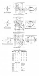
I don't remember where I found this little comparison of output stage circuits - it's been in my audio archive for almost 10 years - but it's interesting, if slightly tangential to this thread. Looks to somewhat duplicate some of the information in Crowhurst's book "Understanding Hi-Fi Circuits". I'll post it here in case someone finds it useful.
[Edit] - It is missing the circuit diagrams for some of the more interesting variations. I'll try and post the pertinent schematics this weekend. "Unity Coupling" is the McIntosh circuit. "Modified Ultralinear" is what the Quad II output could be considered, for a UL ratio of 10% with 10% CFB.
[Edit] - It is missing the circuit diagrams for some of the more interesting variations. I'll try and post the pertinent schematics this weekend. "Unity Coupling" is the McIntosh circuit. "Modified Ultralinear" is what the Quad II output could be considered, for a UL ratio of 10% with 10% CFB.
Attachments
Last edited:
Thanks everyone for the replies. I'm now immersed in even more reading... I still see conflicting reports on whether an optimal UL feedback percentage exists or not.
It doesn't. For example see the attachment. They soon found that 43% doesn't work really well for the 6V6.....
Ideally you should experiment all solutions to know the best (compromise). I have found by chance that 50% UL works really well for tubes like EL84, ECL/PCL 82 and this makes the transformer windings much more practical. The transformer "ideality" should also taken into account.
Inverse polarity respect to the corresponding plate as you want negative feedback.tcqanh said:Hi all,
Does Cathode FB winding have the same direction of DC current or inverse direction to primary winding ?
Regards,
QA.
Attachments
Last edited:
Inverse polarity respect to the corresponding plate as you want negative feedback.
I meant overall polarity. If one doesn't know the polarity it can be found just trying while monitoring the gain closed loop vs open loop.
This looks like a topic to really attract attention of the technically curious! Cool!
Speaking of being immersed in the "classic" literature, I'll iterate something: be careful when interpreting experimental data of others, when it comes to the presentation of tapping ratios. The original Hafler-Keroes paper and later, in 1955 a very detailed article by Langsford-Smith both speak of the ratios as impedance and not voltage ratios. Far from being interchangeable. Why an impedance and not voltage means of ratio measurement, I don't know. Personally, a voltage ratio is both more intuitive to visualize and directly translates to percent of turns for the tapping. Oh, well.
Everything I have both read and tried on different kinds of simulations has convinced me that the optimum UL ratio depends a lot on certain tube characteristics, which includes chosen operating points, etc.
As a long time magnetics engineer, I most heartily agree with the several posts regarding how difficult it is to execute a proper transformer, and how things like tapping, added windings, etc, only make this effort not linearly but exponentially more difficult.
Not to discourage necessary complexity, just to be careful that there is a beneficial net result and not unnecessary and performance destroying side effects. Obviously, there can be good ones, witness the Mac and its multitude of windings and yet its good reputation (for operation in class B, no less).
From the transformer winding standpoint, an optimum tapping is one which occurs at the end of a layer, if layer wound. For a toroid, again mechanically speaking, it really does not much matter. So, for a layer wound (applies to EI, cut C cores, a few other lamination configurations), if you have 600 turns total in five layers, the center tap is kind of cruddy to do (happens at 2.5 layers), G2 taps of multiples of 120 turns from the plates happen on the layer edges (a good thing). So, don't go strictly by the percentage value but by how the unit is layered.
I like that we, collectively, appear to be gaining real understanding on just what and how UL really works, perhaps the only area of truly new learning compared to the giants of the tube past.
We seem to finally be getting away from explaining UL as "feedback" in the classic sense of error detection and correction, and seem to be focusing more and more on what I believe is the real reason UL works: the dynamic altering of the tube's operation by taking advantage of the G2 gm and thus constantly changing conditions due to the percentage of plate swing which is being applied to the G2. I know, way oversimplified but so is calling that connection "feedback".
I'm really seriously thinking of executing my ground-up amplifier using a standard, PP transformer (no UL, in other words) and mechanizing the G2 connection via MOSFETS so both the static G2 voltage and the percentage of coupled swing can be varied and hopefully an optimum operating set of conditions be established.
Now, if only I could inherit enough so work does not get in the way....HMM!
Rene
Chris - you may be right, that the functions all vary monotonically. I think it would be rather nice if true, as it would simplify the design / decision process considerably. I'm curious what has lead you to this conclusion.
There are very good curves in the Mullard amplifier book. It was reprinted by Ed Dell's group a few years ago, so should be available somewhere.
The Keroes and Hafler choice was made as a good sweet spot, where most of the gains had been acheived and most of the downsides were still further away, but *all* of the functions continue in the same directions with tap-percentage changes in the same directions. Not linearly, which allows for a sweet spot.
All good fortune,
Chris
but *all* of the functions continue in the same directions with tap-percentage changes in the same directions.
Hmm, don't quite understand that.
All the early papers I've read clearly indicate that there is no an asymptote but actually a reversal of at least some characteristics, indicating not monotonicity but an actual sweet spot. I think the assumption at least Hafler/Keroes made which is not correct, is the assertion that a single value of tapping at 43% impedance was optimum no matter what. Lansgford-Smith did not think that there is a universal tapping point after he got thru with his experiments. But all of them conclude that a properly executed UL is better than either pentode or triode, for composite reasons to be sure but, better than either.
Just the way I see it, more than willing to be shown differently.
Rene
- Status
- This old topic is closed. If you want to reopen this topic, contact a moderator using the "Report Post" button.
- Home
- Amplifiers
- Tubes / Valves
- UL / Distributed Load - Screen vs. CFB Winding Ratios