Hi, Perhaps this may be a quick question:
So I am in the process of designing a ribbon microphone. I am getting alot of my info from "http://www.diyaudiocomponents.com" and was wondering what a suitable preamp would be for a 4mm wide 2.5u thick ribbon in between two neodymium magnets (2"x1/4"x1/4").
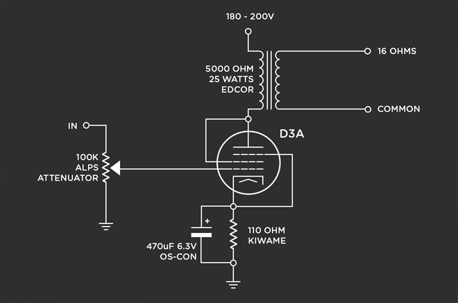
I prefer a simple and minimal component count preamp design and I think I landed on one. Check out the image below. A single pentode wired like a triode? Whatever it may be, I enjoy the concept of single stage amps.
Being that I didnt fabricate the microphone yet, I dont know the impedance of the ribbon. But when I do measure the impedance of the microphone, what is the process for setting the proper resistor value at the input to match the impedance?
I also heard somebody mutter the idea of using a potentiometer to accommodate a wide range of impedances. But my question as well is how do you tell by ear that the microphone is loaded properly?
Some Preamps have input attenuation and output (gain) control. Should I consider all that? This one schematic I supplied doesn't feature any of those.
So I am in the process of designing a ribbon microphone. I am getting alot of my info from "http://www.diyaudiocomponents.com" and was wondering what a suitable preamp would be for a 4mm wide 2.5u thick ribbon in between two neodymium magnets (2"x1/4"x1/4").
I prefer a simple and minimal component count preamp design and I think I landed on one. Check out the image below. A single pentode wired like a triode? Whatever it may be, I enjoy the concept of single stage amps.
An externally hosted image should be here but it was not working when we last tested it.
Being that I didnt fabricate the microphone yet, I dont know the impedance of the ribbon. But when I do measure the impedance of the microphone, what is the process for setting the proper resistor value at the input to match the impedance?
I also heard somebody mutter the idea of using a potentiometer to accommodate a wide range of impedances. But my question as well is how do you tell by ear that the microphone is loaded properly?
Some Preamps have input attenuation and output (gain) control. Should I consider all that? This one schematic I supplied doesn't feature any of those.
This will be extremely noisy. A ribbon impedance is likely to be an ohm or less, and the equivalent noise resistance of a pentode will be 1k or more. If you use a step up transformer (30:1 is typical), the source impedance seen by the tube is going to be several hundred ohms, which is at least in the ballpark for triodes- then you have to fight the effect of the input capacitance on the transformer... Tube preamps for low output, low source impedances are NOT trivial to design!
Oh wait, I dont know if this adds to your statement, but on the microphone, there will be a step up transformer inside from Edcor.
EDCOR - RMX1
This transformer is 1:37. The output DCR of the transformer is 87 Ohms. Will this make it more apropriate for a tube preamp to function less obnoxiously?
EDCOR - RMX1
This transformer is 1:37. The output DCR of the transformer is 87 Ohms. Will this make it more apropriate for a tube preamp to function less obnoxiously?
D3a is a MUCH better choice. This still won't be ultra quiet, but it will be a phuc-ton quieter than a 6AU6!
You'll want a much quieter supply (DC on heaters, elevated heater potential, common mode filtering, snubbered HT secondary), since a pentode will not have good power supply rejection.
You'll want a much quieter supply (DC on heaters, elevated heater potential, common mode filtering, snubbered HT secondary), since a pentode will not have good power supply rejection.
If I were to use a D3A in this schematic, should I go about using this similar layout, (no cathode resister) etc or should I do cathode bypass like this:
How would you recommend going about redesigning for the D3A? What about impedance matching? attenuators for load matching?
The power supply I'm not too worried about, I have some chokes I can use etc.
How would you recommend going about redesigning for the D3A? What about impedance matching? attenuators for load matching?
The power supply I'm not too worried about, I have some chokes I can use etc.
RCA was/is famous for their "velocity", AKA ribbon, microphones. They used a SUT into a 6SL7. Other than RIAA equalization, this situation is quite analogous to that found in handling a LOMC phono cartridge.
If you're willing to "wrestle an alligator", consider the Russian 6C45П (6s45p), as the 1st tube the signal "hits". That tube, like the 5842, comes perilously close to oscillating, while being stored in its cardboard box. EXTREME measures that suppress parasitic oscillation are very much in order. Place a 5.6 KOhm carbon composition "stopper" on both grid connection points. Place a 100 Ω carbon film "stopper" on the plate connection point. Finally, place ferrite beads on the heater power wires, as close to the socket as you can get.
If you're willing to "wrestle an alligator", consider the Russian 6C45П (6s45p), as the 1st tube the signal "hits". That tube, like the 5842, comes perilously close to oscillating, while being stored in its cardboard box. EXTREME measures that suppress parasitic oscillation are very much in order. Place a 5.6 KOhm carbon composition "stopper" on both grid connection points. Place a 100 Ω carbon film "stopper" on the plate connection point. Finally, place ferrite beads on the heater power wires, as close to the socket as you can get.
Oh man, I never heard about this Russian magic before,
DIY 6c45 Amplifier
sounds like a cult classic. It probably isnt realistic to have a 6s45p be OTL right?
In fact, is there a OTL preamp thats minimal like this? Regardless, Im realy starting to dig this mini magic trick
DIY 6c45 Amplifier
sounds like a cult classic. It probably isnt realistic to have a 6s45p be OTL right?
In fact, is there a OTL preamp thats minimal like this? Regardless, Im realy starting to dig this mini magic trick
You might end up going through *two* input transformers to get things acceptably quiet, one in the mic and one in the preamp. Ribbon mic output levels are measured in mouse farts per furlong, and that's on a good day. Sounds like a fun project, fersure. What are you using for magnets?
All good fortune,
Chris
All good fortune,
Chris
If I were to use a D3A in this schematic, should I go about using this similar layout, (no cathode resister) etc or should I do cathode bypass like this:
That's a very odd circuit choice. All you really want your mike preamp following the 1:37 transformer to do is give you 60-80dB of flat, quiet gain and be able to drive the (usually) 2-10k impedance of the recorder or console. You're not going to get that much gain out of one stage and you'll want variability of gain as well.
Before embarking on a design, it helps to specify the target. I've given you a couple of pieces of it- you need to fill in the rest. What's the environment for the preamp (studio or location)? Length of cable to the recording device or mixing console? Input impedance of the recording device or console? Level needed by the recorder or console?
You may have gathered that is is a very advanced project, and it is; besides circuit design, layout, power, grounding, mechanical isolation will all be ultra-critical and can't be picked up willy-nilly from web searches. You might consider doing a simple chip-based design first, get it debugged and working, then move on to a tube design. You'll save a lot of money this way, you'll at least have your mike up and running during the LONG process of getting the tube unit running, and you'll attack the super-hard problem of the tube unit after having learned a lot of lessons from the chip-based unit. You will at minimum need a good signal generator and oscilloscope as well as a good voltmeter before even beginning this.
To put it in perspective, I've been designing and building tube gear for 45 years, and when I did my ribbon mikes two years ago, I found it to be a daunting project and not trivial to get right.
Hy SY,
The scenario I would be using this amp arrangement would be casual / partial studio set up. I don't envision running around with the amp I would design with it. I have made a few tube amplifiers, but none for recording. Call this project my entry project into audio "recording".
In the immediate, my macbook pro is acting as my archiving tool (Input impedance: > 20 kΩ). As you can see that this is my entry project into recording
One of the big challenges is that I haven't physically constructed the microphone yet so I cant get precise figures on the output of the design yet (only estimations).
Im looking for a great simple / minimal design for this scenario. That russian tube was winning me over for its capabilities.
You really need another transformer at the input to the tube.
The Edcor in the mic only raises the ribbon signal to normalish microphone levels - a few millivolts at most. A single triode wired pentode will not only not have enough gain but will also be noisy. You really need a 1:10 step up microphone transformer at the input to the stage. This will give you another 20dB of gain which, with the 30dB or so you will get from the 6AU6 will be just about enough for most applications and improve the noise by nearly 20dB
Cheers
Ian
You're going to have fun with ribbon tensions and things. I haven't ever actually built a ribbon microphone, but I've tested plenty, and reribbonned several. Cleanliness is definitely close to godliness; they draw in every iron filing within a kilometre radius.
Treat the microphone and the preamplifier as two different projects. The output of the transformer on the mic itself should give a nice 200Ω balanced circuit that you can wire into an XLR and test in any decent mic preamplifier; you'll know it works all right. Then the preamplifier gets an input transformer (when everyone was designing round tubes all professional mic inputs had transformers) giving you about a 1k balanced input impedance, an output transformer (not essential, but nice) and maybe even a gain switch, and you can test it out with any decent lowZ dynamic microphone, and even put an instrument DI into it for those moments when you don't need a microphone, but do want an electric guitar to sound really good (and clean).
Since ribbons, large ribbons anyway, have a gentle HF rolloff, Wes Dooley recommends the option of a very gentle (sort of 3dB/octave gentle) HF boost, switchable. This should be possible with a tube preamp (not, you notice, easy) but I can't see how to with just one tube.
Power supply wise I see no advantage in tube rectifiers; solid state are cheaper, last longer, and leave enough space to put in another tube for advanced gain control, frequency tweaks, whatever. Just make sure the main smoothing caps have a little voltage reserve (one from my youth; if you use a tube rectifier, it needs a separate heater winding. The cathodes are right next to the heaters, and they're at +ve HT, while the heaters on the preamp tubes are almost at ground. Too much risk of shorts.)
Rectify and stabilise heater voltages, rather than go for a hum balance, and if possible put some electrostatic screening between diodes and signal; in a mic preamp you've got some very low levels at very high impedances.
Oh, I see most of my points have already been made. Never mind, independent corroboration is not a bad thing.
Last edited:
Hi chrispenycate, thanks for all the juicy tips.
I dont mind using input and output transformers for this level of amplification, (if it means appropriate results).
One of the major challenges I am trying to navigate is finding a hit-home design I can reference.
I never had to deal with input transformers, and I also dont know any rule of thumb formulas on how to match the impedance of them.
Impedance matching... still looking up information on it to make real opinions on exactly what I need. Tips?
Hi chrispenycate, thanks for all the juicy tips.
I dont mind using input and output transformers for this level of amplification, (if it means appropriate results).
One of the major challenges I am trying to navigate is finding a hit-home design I can reference.
I never had to deal with input transformers, and I also dont know any rule of thumb formulas on how to match the impedance of them.
Impedance matching... still looking up information on it to make real opinions on exactly what I need. Tips?
The rule of thumb for microphone input transformers the input impedance should look like about 10 times th source impedance of the microphone driving it. Most mics have a source impedance of 150 ohms or less so you should aim for an input impedance of 1500 ohms or so. 150K on the secondary of a 1:10 mic transformer will be reflected to the primary and look like about 1500 ohms. Suitable mic transformers are made by Jensen, Cinemag, Sowter and Lundahl.
If you want to look at a reference design look here:
Poor Man' s Tube Mic Pre Channel Strip (Eurochannel)
Cheers
ian
Hi Ruffrecords,
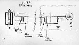
Thanks for giving some pointers. Just to clarify, I drew a little picture illustrating the area of contention.
So just to be sure:
This Ribbon mike is gonna have a very low impedance. To step up the voltage, I will be using the EDCOR RMX1:
http://www.edcorusa.com/p/345/rmx1
Its secondary is rated around 87ohms.
So to match the impedance on the input transformer (preamp side), the input transformers primary should be aprox 10 times the amount of dampening of the output of the RMX1 transformer.
So I should be looking for a input transformer with a value around 870 ohms? How precisely does the secondary correlate with this value and what does it mean for the rest of the amp. Does the secondary play an effect on the primary?
or is my diagram rather far off from what is being described here...
Attachments
Would something like this one work?
EDCOR - WSM600/15K
600ohms on the primary and 15k on the secondary? How do you address the load for the grid? other resistors required? etc stuff
EDCOR - WSM600/15K
600ohms on the primary and 15k on the secondary? How do you address the load for the grid? other resistors required? etc stuff
OK, you are confusing winding dc resistance with impedance and also output transformers with input ones.
The 0.4ohm and 87 ohm figures given for the Edcor ribbon mic transformer refer only to the dc resistance of those windings. Provided the inductance of both winding is high enough then the impedances are determined by the source and load impedances.
For the ribbon mic transformer the source impedance is the ribbon resistance itself which is probably around 0.1ohm. This is reflected by the transformer into the secondary by the turns ratio squared. So from the secondary the ribbon 'looks like' 0.1 x 37 x 37 ohms =~ 140 ohms. So, to the outside world, which knows nothing of what's inside your mic, it looks like a source of around 140 ohms, pretty much like many other mics.
In order not to lose too much signal, you want to aim for the mic pre to have an input impedance of around 10 times the mic impedance. If it was equal to the mic impedance, for example, you would lose 6dB of signal. Since most mic pres expect to be fed from mics with around 150 ohms source impedance, they are typically arranged to 'look like' 1500 ohms to the outside world. We are not trying to 'match' here, but simply to ensure minimal signal loss,
Now, if in a tube based mic pre you have a 1:10 input transformer, if you load the secondary with 150K, this will be reflected back to the primary by the turns ratio squared (10 X 10) and will 'look like' 150K/100 = 1500 to the outside world. So looking at the primary side, your 140 ohm mic is loaded with 1500 ohms.
However, your 140 ohms mic gets reflected to the secondary by you know what now, so it 'looks like' 140 X 100 = 14K at the secondary. So, looking at the secondary we have a source of 14K loaded by 150K.
The important lesson here is that transformers do not have an impedance - they simply reflect impedances connected across the primary and secondary windings. Of course, transformers need to be designed to work best with certain primary and secondary impedances which is why you will see them labelled as 15k: 150 for example but it is important to remember that these are not intrinsic values just preferred load values.
You picked the right ratio for your mic transformer but the model you chose is an output transformer - suffice to say it is designed to drive a 150 ohm load, not be driven by one. If you want to use an Edocr then a suitable model would be the MXL10.
Cheers
ian
- Status
- This old topic is closed. If you want to reopen this topic, contact a moderator using the "Report Post" button.
- Home
- Amplifiers
- Tubes / Valves
- Ribbon Microphone Preamp