Shot noise depends on I, but in a valve you never get pure shot noise because of space charge smoothing. This makes shot noise act more like thermal noise, which when expressed as current or voltage depends on slope resistance dV/dI. Hence your feeling is likely to be wrong. Physical intuition is often wrong, unless very carefully guided by a good theory.mm7 said:but I have a feeling that a noise does not depend on dV or dI. It should depend on absolute values of V or I.
You still seem to be persisting in wanting to use my gm estimate as though it were a good approximation which gives the correct variation with circuit parameters. It is an estimate - it gives a ball-park figure. That is all. Insert it into another formula at your peril.
Now to be a little less approximate, for a triode which accurately follows the 3/2 rule (i.e. few real triodes!) it can be shown that anode impedance rac = (2/3) Rdc (1 + (mu Vg/Va) ). The value of the last term depends on biasing, but broadly mu Vg/Va will be around -0.5 so we end up with rac = Rdc/3. Note that if you use this formula as it stands it will mislead you about the Va dependence, yet it does give a rough estimate.
At low currents some triodes are more like a 5/2 rule so you might get rac = Rdc/5. Still a valid estimate.
If you have a good test set to check, with FFT, the region between 50 to 400 Hz you can see that the noise floor is not so low as you think with also the harmonics multiple of to 60 Hz ( or 50Hz) .
The filtering you use is OK for line preamp but to kill the ac residual form rectifier the best way is regulated supply or battery.
Regarding the calculation on noise, the start point is only the Req that is related to any tube and declared in every data sheet.
Bye
Walter
The filtering you use is OK for line preamp but to kill the ac residual form rectifier the best way is regulated supply or battery.
Regarding the calculation on noise, the start point is only the Req that is related to any tube and declared in every data sheet.
Bye
Walter
Hi,
I wouldn't count on the Req in the datasheet to assure low noise performance at LF frequencies.
However, the lowest noise triodes (at LF as well) are invariably the ones sporting a frame grid type construction.
Other than that it's a matter of section of the tubes, lower Vf helps and, since I assume the mic can work with a low Zin, you could try worked at starved plate voltages (12 to 15VDC) and use a CCS as plate load to maximize the gain of the stage.
Ciao,")
Regarding the calculation on noise, the start point is only the Req that is related to any tube and declared in every data sheet.
I wouldn't count on the Req in the datasheet to assure low noise performance at LF frequencies.
However, the lowest noise triodes (at LF as well) are invariably the ones sporting a frame grid type construction.
Other than that it's a matter of section of the tubes, lower Vf helps and, since I assume the mic can work with a low Zin, you could try worked at starved plate voltages (12 to 15VDC) and use a CCS as plate load to maximize the gain of the stage.
Ciao,
The Req listed is the start point to make some calculations; the real circuit is always gives you the answer but you need a good test set.
A good solution to solve the problem is the use of ECC88 and the use of balanced circuit also to refuse the current common mode issues ( if not battery are used).
Every mic is balanced as the input transformer so will be easy to make the circuit.
Walter
A good solution to solve the problem is the use of ECC88 and the use of balanced circuit also to refuse the current common mode issues ( if not battery are used).
Every mic is balanced as the input transformer so will be easy to make the circuit.
Walter
Hi,
That model is actually a step down xformer according to the datasheet.
What you need is a SUT, no? LL has several models for that purpose, including for ribbon mics.
Also, the 1Meg you state is likely you gridleak resistor but that does not determine the actual input impedance.
Not sure I understand where you're going with all this but bottom line is that you just can't rely on noise figures given in datasheet. Anything else, including noise levels is determined by the circuit.
Ciao,
I use Lundahl LL1935 input transformer in 1:5 configuration.
That model is actually a step down xformer according to the datasheet.
What you need is a SUT, no? LL has several models for that purpose, including for ribbon mics.
Also, the 1Meg you state is likely you gridleak resistor but that does not determine the actual input impedance.
Not sure I understand where you're going with all this but bottom line is that you just can't rely on noise figures given in datasheet. Anything else, including noise levels is determined by the circuit.
Ciao,
First of all , do you use a balanced circuit?
If yes the use of ECC88 is very good because you got a high gain in addition with a 1:20 trafo (26 dB).
Please don't use an high value of resitor across the secondary of trafo.
If you mic has an impedance around 1 ohm, with a 1:20 ratio you can use a resistor of 20k that give you a reflected impedance on primary of 50 ohm that is fine.
Different if you use a 1:40 trafo ( I suggest this one), maybe 50k is enough to get about 40 ohms.
If you use the 6C45 it has a high Cag that can give you a roll off at high freq. if the input impedance is high.
Another reason to use the ECC88/6922 soviet is related to microphony that in this type is very low
Bye
Walter
Frank, yes the LL1935 is step down, but it can be used as SUT. This is recommend to me by Per Lundahl himself after I informed him about my setup and target.Hi,
That model is actually a step down xformer according to the datasheet.
What you need is a SUT, no? LL has several models for that purpose, including for ribbon mics.
Also, the 1Meg you state is likely you gridleak resistor but that does not determine the actual input impedance.
Not sure I understand where you're going with all this but bottom line is that you just can't rely on noise figures given in datasheet. Anything else, including noise levels is determined by the circuit.
There is already 1:37 SUT in the ribbon mic. Then from secondary of this ribbon SUT it comes to secondary of LL1935, so it works as 1:5 SUT.
Yes 1M is grid leak resistor. I read that it determines input impedance for tubes.
If it is not, could you please advise how to calculate an actual impedance.
I do not rely on numbers in data sheet, because it is most likely oriented for UHF/RF use. I just read good feedback about this tube as a low noise one.
However in my case this produces quite significant pink noise that I am trying to find how to reduce.
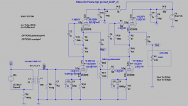
Here is my current schematic.
Attachments
Last edited:
"""Then from secondary of this ribbon SUT it comes to secondary of LL1935, so it works as 1:5 SUT."""
This is wrong!
if the signal comes from a trafo ( how much is the nominal output signal?) it is balanced.
So the use of a double triode as 6922 is fine
The schematic you post is too complicated for this job, in my opinion.
Walter
This is wrong!
if the signal comes from a trafo ( how much is the nominal output signal?) it is balanced.
So the use of a double triode as 6922 is fine
The schematic you post is too complicated for this job, in my opinion.
Walter
Why?"""Then from secondary of this ribbon SUT it comes to secondary of LL1935, so it works as 1:5 SUT."""
This is wrong!
It is 30uV from ribbon mic 1:37 traffo.if the signal comes from a trafo ( how much is the nominal output signal?)
what schematic would you propose?
Hi,
Not to mention all the unnecessarily high value caps, cathode bypasses where there's little point having them, why the 3K3 load at the output, etc., etc.
Also, if the mic already contains a SET, why the second one?
The secondary windings will also need proper loading (which the manufacturer can tell you).
The log pot has a frequency dependant Zout as well and, I don't know what this will be connected to on the output end but IMO, that's where a SE OTP comes in handy.
There's work to be done, flicker noise would be the least of my worries here. Sorry Mm7.
Ciao,
The schematic you post is too complicated for this job, in my opinion.
Not to mention all the unnecessarily high value caps, cathode bypasses where there's little point having them, why the 3K3 load at the output, etc., etc.
Also, if the mic already contains a SET, why the second one?
The secondary windings will also need proper loading (which the manufacturer can tell you).
The log pot has a frequency dependant Zout as well and, I don't know what this will be connected to on the output end but IMO, that's where a SE OTP comes in handy.
There's work to be done, flicker noise would be the least of my worries here. Sorry Mm7.
Ciao,
Last edited:
Req in data sheets applies to all mid frequencies. That is, above the point where 1/f noise is relevant and below the point where induced grid noise becomes a problem. Typically, this means from 10's of kHz up to 10's of MHz.
If you have grid current (possible with very low anode voltages but vaguely normal currents) then this can generate extra noise. This is a form of partition noise. It will also reduce input impedance.
If you have grid current (possible with very low anode voltages but vaguely normal currents) then this can generate extra noise. This is a form of partition noise. It will also reduce input impedance.
high value caps are calculated in LTSpice. Lower values shrink LF.
3K3 load at the output is impedance of my sound card (EMU0404) that this preamp will be used with.
At time when I've built the ribbon mic, I had information that 1:37 should be enough to bring ribbon level to level of dynamic mic. Then I've built preamp based on 12AX7 and found high white noise level, so I've added input SUT.
I would agree that 1:150 transformer would be better. But existing schematic works well sound-wise, except the pink noise. BTW previous one, same topology, but built on 12AX7 and 6N23P tubes did not have flicker noise.
Regarding the use of two trafo it is wrong because each one must have a proper optimal Z load.
With the configuration you are trying this aspect is not satisfied.
About the nominal output voltage is 30 microvolt at the output of ribbon?
With ratio of 37 you will have 1,1 mV at the output of the trafo.
In this case you need absolutely a Fet stage (balanced configured and battery powered) to increase minumum of 26 db (20 times ) the signal. In this case you get about 25 mV that is enough to drive a tube stage with a proper s/n.
No way to have a good results, as quality sound and s/n ratio, with a very little voltage on input of a tube stage and more is the gain more you can get a "wind" noise (white noise) at the output
With a additional fet stage ( as Schoeps and others manufact.) you will find a right solution
Walter
Last edited:
If you have grid current (possible with very low anode voltages but vaguely normal currents) then this can generate extra noise. This is a form of partition noise. It will also reduce input impedance.
Anode voltages are about 100V. How to check if there is grid current? If I put 1uF on grid, it should stop grid current. So if noise will disappear it means it was caused by grid current?
Again, this traffo was recommended by Lundahl - manufacturer of both traffos 1:37 and 1:5. I've described him what I need, he recommended LL1935 in SUT config.Regarding the use of two trafo it is wrong because each one must have a proper optimal Z load.
With the configuration you are trying this aspect is not satisfied.
Even worse. 30uV is after 1:37. Ribbon itself produces 1-2uV at 60dB volume.About the nominal output voltage is 30 microvolt at the output of ribbon?
With ratio of 37 you will have 1,1 mV at the output of the trafo.
In this case you need absolutely a Fet stage (balanced configured and battery powered) to increase minumum of 26 db (20 times ) the signal. In this case you get about 25 mV that is enough to drive a tube stage with a proper s/n.
No way to have a good results, as quality sound and s/n ratio, with a very little voltage on input of a tube stage and more is the gain more you can get a "wind" noise (white noise) at the output
With a additional fet stage ( as Schoeps and others manufact.) you will find a right solution
My challenge was to built a preamp purely on tubes.
But I probably will have to opt to this fet stage, if all other "silicone-less" methods wont help.
- Status
- This old topic is closed. If you want to reopen this topic, contact a moderator using the "Report Post" button.
- Home
- Amplifiers
- Tubes / Valves
- Ribbon Microphone Preamp