an old BIG tube oscilloscope. Donor parts for Africa includng a huge FO power transformer with about a gazillion tappings. Then take a quick search in this and the tools forums - the issue has come up before a number of times
Or, trawl the surplus gear places you guys in the 48 are so lucky to have on your back doorstep...
Or, trawl the surplus gear places you guys in the 48 are so lucky to have on your back doorstep...
I have a couple of these.
Heathkit IP-17 HV Power Supply
I found one older version available at Ebay now:
Heathkit IP 32 Regulated Power Supply | eBay
One possibility is to build your own.
With power NFET's it can be guite compact.
Heathkit IP-17 HV Power Supply
I found one older version available at Ebay now:
Heathkit IP 32 Regulated Power Supply | eBay
One possibility is to build your own.
With power NFET's it can be guite compact.
As for requirement, I need two plate voltages (one for output tube and one for driver tube), 2 or 3 low voltage sources for the heaters.
If you want to play with fixed bias, you'll need a -ve supply also.
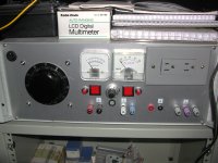
I made my own basic setup out of leftover/scrap parts.
HV is a variac connected to an old 360-0-360 tube TV transformer through a CLC with 500V rated caps. IIRC it's good for around 150ma and around 450V.
-ve bias is a small transformer (around 44V I think) with a CRC filter and a simple pot to give up to about -60VDC bias.
The two square illuminated buttons turn on the HV or bias supplies.
A filament transformer that is 12.6V-0-12.6V with all 3 taps on the front panel to provide either 6.3 or 12.6VDC.
The variac also controls the mains VAC on the receptacle for powering up stuff slowly. That feature is used the most by far........
Low-Tech, but works fine for my needs.
EDIT: Here is a fancier one by Pete Millett.....tube regulated
http://www.pmillett.com/HV_bench_supply.htm
Attachments
Last edited:
Agree with aardvarkash10 on the BIG old oscilloscope transformer. I have one from a 545 Tektronix, and it has a lot of relatively low voltage (2x 115V, 138V, some more) secondaries and about 5 or 6 6,3V windings with lots of A. I connected the HV secondaries (noticing phase) to a Euro barrier strip, allowing for series connection.
To use these I made 4 individual power supplies. Each power supply consists of a bridge rectifier and two stacked elco's (with bleeding R), allowing it to operate both as 'bridge' as 'voltage doubler'. Each elco is 250V, so I aim for a max of 450V DC. I use a LR8N3 together with a big 300k wirewound 10 turn pot to set output voltage up to ~420V. This output voltage feeds the gate of a 600V NFET, that operates as pass device. I blew-up two of these FETS due to the lack of a short circuit protection, but it shouldn't be hard to implement one.
For operation I feed the (series connected) HV secondary which is most suitable for the desided output voltage to the PS board, to reduce heat dissipation on the heatsink.
As artosalo said: working with NFETS can indeed make for quite a compact build.
Finding a power supply that will meet all your needs will likely be a challenge. Maybe someone knows of an old tube supply that'll work. But I suspect you'll end up with one supply for the high voltage and a couple for the various filament voltages.
A Sorensen QRD 20-4 would be ideal for filaments. I have a QRD 40-2 (40 V, 2 A). I think I paid an entire $30 for it...
The B+ supply, I'd make from a HV transformer and a variac like Boywonder suggests. It takes about 15 minutes to solder the rectifier parts together and strap them to a piece of plywood. BAM! Done.
~Tom
The B+ supply, I'd make from a HV transformer and a variac like Boywonder suggests. It takes about 15 minutes to solder the rectifier parts together and strap them to a piece of plywood. BAM! Done.
Since you put it that way, I might do that.
I have a Heathkit variable supply myself. Tube regulated and works great. I recapped it and replaced a few resistors when I got it. I also had to retube it as there were a few bad tubes, but now it works like a champ.
If you do get a Heathkit, I would suggest that you add a choke that can handle 200ma. The output isn't "dead quiet" as you would probably like, however it does get the job done until you want to build your own supply for your amp.
If you do get a Heathkit, I would suggest that you add a choke that can handle 200ma. The output isn't "dead quiet" as you would probably like, however it does get the job done until you want to build your own supply for your amp.
Let's say I build an amp circuit with bench PS.
When I am ready to build the PS for that amp, should I build the PS outside first (on plywood) or I can just mount all the PS parts in the final chassis then wire everything up ?
How do you guys approach from start to finish when building a tube amp ?
When I am ready to build the PS for that amp, should I build the PS outside first (on plywood) or I can just mount all the PS parts in the final chassis then wire everything up ?
How do you guys approach from start to finish when building a tube amp ?
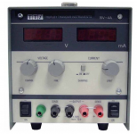
I have a few Thurlby bench power supplies - really like them. Big digital readouts for volts and amps. I use them all the time. I have a couple supplying my DHT output stages (4P1L PSE) right now, and they also sound good. They commonly come in 30v 2A, or 15v 4A so I have some of both. Bought them off ebay and they've been ultra reliable.
Attachments
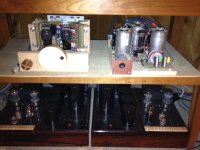
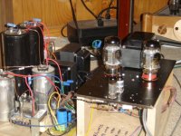
I build on a piece of plywood, tweek till I get it where I want it and then put it in a case. Simulations are good up to a point. The top shelf is a 6v6 bootstrapped preamp and its power supply sitting next to it. Underneath are my Modern Mullards or OPUS's. (initially built the same way. as seen in the second photo.
Not a good technique with kids and pets. But works well in a lab as it is easier to get measurements and change parts.
Not a good technique with kids and pets. But works well in a lab as it is easier to get measurements and change parts.
Attachments
I build on a piece of plywood, tweek till I get it where I want it and then put it in a case. Simulations are good up to a point.
Since you gotta build the PS in the designing stage anyway, then what is the purpose of having bench power supplies ?
You can build it out on a piece of plywood and use a resistor for the load of both channels (if you are using one supply for both channels). Adjust until you get your voltage right and then rebuild it into whatever chassis that you want, either wiht the amp or in a separate case.
The thing to remember is if you have to add dropping resistors for your PS on one channel, then you have to change your PS before it will work supplying two channels.
For instance if the resistance of your circuit for one channel is 5k and you design your PS to deliver voltage at that resistance (or current draw), then you would need to change it before using it to power two circuits like that. Make sense?
Let's say I build an amp circuit with bench PS.
When I am ready to build the PS for that amp, should I build the PS outside first (on plywood) or I can just mount all the PS parts in the final chassis then wire everything up ?
How do you guys approach from start to finish when building a tube amp ?
I want to get some used decent bench power supplies. I will mainly be working with tube equipment.
.....what is the purpose of having bench power supplies ?
huh?
")
All kidding aside, they come in handy if you want to breadboard tube stages, quickly try different B+ voltages, bias, etc.
If your long term plan is to build one or two amp projects, you may not need a bench supply. Using PSUDII and breadboarding your amp PS will get you where you want to go in that case.
huh?
Haha.
I should said I am considering to get bench PS.
Thanks for clearing it up.
So the bench PS allows me to experiment before having to build the actual PS.
This way I can just build the actual PS for the final circuit.
Then you're gonna be relegated to getting a couple different boxes:I really don't want to build a PS.
1 - A "bog-standard" 0-30V 1-3A bench supply, preferably dual output, for filament supply and (if it is dual) bias
2 - An HT supply for your plate voltage - this can be expensive if you're not gonna build it yourself.
One alternative is to find an Electrophoresis supply from a used lab equipment dealer or from eBay. These typically top out at either 500V or 1000V (although there are some low-current models that reach 15000 or even 2000V), and can often be had pretty cheaply. Trick is to find one with enough output current.
Really though, if you're gonna build tube circuits, then making a high-voltage supply shouldn't be a big deal. As has been said, get a trafo from a scope (or this: EDCOR - TBPWR-HV1-120) and throw a DPDT "rectifier switch" on it (to go from full-wave to bridge), giving you two voltage ranges ("200/225/250/275/300V & 400/450/500/550/600V in the case of the Edcor trafo) and use a double-pole multi-position rotary switch to select the transformer taps. Put a decent CLC filter behind it and voila!
In any event, good luck on your quest.
- Status
- This old topic is closed. If you want to reopen this topic, contact a moderator using the "Report Post" button.
- Home
- Amplifiers
- Tubes / Valves
- Bench Power Supply: What to look for ? Which one to get ?