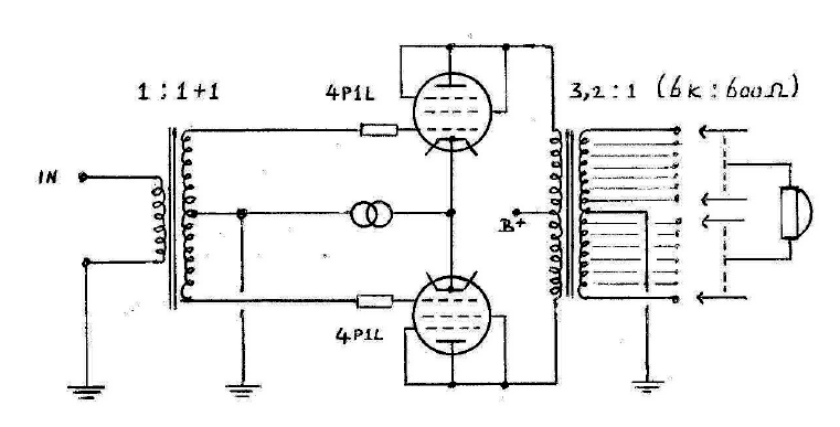
Pieter's schematic for those who just wish to glance at the design.
And two excerpts:
And two excerpts:
Apart from the output transformer I do not claim to be original, and please note this design has not been built yet.
Very likely transformer winding ratios and load impedances need some experimentation.
My inspiration comes from the designs of Lynn Olsen and the late Allen Wright.
The input transformer is a 1:1+1 phase splitter; it is wound on a nanocrystalline toroidal core, and it is the same as used in Lynn Olsen's Karna amplifier.
The two 4P1L tubes work in pushpull class A; the cathodes see a common current source (or better "sink"?) like Allen Wright's PP 300B design. For this application I think there is enough headroom without the risk of the current sink running out of "steam" causing hard clipping.
Why pushpull? I want to maintain the high permeability of the output transformer in this design; with a single ended output stage the required airgap would impair permeability, and besides the SE topology would require an additional gain stage. A pushpull transformer will be smaller than an SE one which is good for winding capacitance and DC resistances.
This output transformer is rather special. Primary impedance ratio is 6k anodeanode with a 600
ohm load across the full secondary; at the same time it will function as an inductive volume control.
It will have a nanocrystalline cut ccore with a very minor airgap to withstand minor DC imbalance, at the same time maintaining permeability . This core material is also known as "Finemet".
The idea is this: the output transformer is basically 6k anodeanode (the 6k is not yet fixed), and 600 ohm secondary. Step down ratio therefore is 3,16:1. The secondary is center tapped to keep
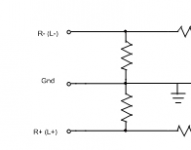
everything symmetrical. I like the idea to drive a headphone with a balanced signal.
The secondary winding has a number of taps which, attached to a 24 position switch (Elma or a cheapo Chinese one), functions as volume control and impedance matching at the same time.
At maximum volume we have a 6k 600 ohm ratio; one step down (a minus 3 dB tap) and we have already a 6k 300 ohm ratio; 2 steps down gives 150 ohm, 3 steps down 75 ohm, and 4 steps down (minus 12 dB) gives a proper drive for a 38 ohm load. We can use all our further steps down to control the volume, at the same time having a 6k 38 ohm ratio or better. In other words: in practice the tubes will always see a very high load impedance which is good for linearity.
Why not keep it all direct heated with a 5R4 rectifier.
Semi choke input (0.5 uF) followed by two chokes to split the power supply for each channel.
Each channel an additional CLC.
Options for regulation (shunt?); this is just one example of many possible power supplies.
Cathode/filament supply by Rod Coleman.
Attachments

Last edited:
Please find attached the pdf.
Personally I find this interesting because vapourware might turn into hardware.
I read the article of Pieter and a little correction i like to make: amourphous nano crystalline material? It should be amorphous OR nano crystalline because amorphous means without crystal structure.
A long time ago i made a transformer for a Stax electrostatic headphone based on a amorphous c-core. Mr Treurniet listened to my transformer. I know for sure that he had not such a transformer in the past, maybe he has now but i would be surprised if he really did.......
May I make a little correction to the little correction ?
This particular PDF speaks about "More recent are core materials like amorphous alloy (iron or cobalt based), and amorphous alloys with a nanocrystalline structure."
Isn't the case that this material starts as a amorphous alloy and then that material gets a heat treatment where a nano crystalline structure is created ?
The addition of the 'with a' is already a nuance ...
I read the article of Pieter and a little correction i like to make: amourphous nano crystalline material? It should be amorphous OR nano crystalline because amorphous means without crystal structure.
May I make a little correction to the little correction ?
This particular PDF speaks about "More recent are core materials like amorphous alloy (iron or cobalt based), and amorphous alloys with a nanocrystalline structure."
Isn't the case that this material starts as a amorphous alloy and then that material gets a heat treatment where a nano crystalline structure is created ?
The addition of the 'with a' is already a nuance ...
Yes that's indeed the case. Nano crystalline materials are heat treated amorphous materials. But after heat treatment it ain't amorph anymore.
From personal experience with transformers for headphones I agree highly with the assesment that the low level signals being dealt with need more than just a typical iron core OPT. P-P is a good way to deal with the transformer issue, but I think I would want an amp with more gain than this.
Nano crystalline materials are heat treated amorphous materials. But after heat treatment it ain't amorph anymore.
The word you are looking for is 'devitrified'. It may be neither crystalline nor amorphous, but a in-situ composite material of nanocrystallites grown within amorphous matrix. If it is fully devitrified, it may still be 'nanocrystalline', but no longer 'amorphous'.
From personal experience with transformers for headphones I agree highly with the assesment that the low level signals being dealt with need more than just a typical iron core OPT. P-P is a good way to deal with the transformer issue, but I think I would want an amp with more gain than this.
From Pieter:
What gain (power) do you want? What do you want to drive?
I just checked specifications of all currently available Sennheiser and AKG headphones, for which class this design is meant, as indicated in my PDF.
With the typical 2 VRMS of a DA converter you can easily permanently damage your ears with this design driving any of these cans.
As also indicated, to drive the least sensitive of headphones like the AKG K1000, this design requires an additional gain stage.
Last edited:
Interesting output transformer. I know we are talking about headphone amplifiers here, but Pieter's design would probably work quite well as line stage as well.
Has Pieter given any hint regarding pricing of these transformers? OPT's will have lots of taps (about 50 I think, because of 24 steps in balanced fashion).
Has Pieter given any hint regarding pricing of these transformers? OPT's will have lots of taps (about 50 I think, because of 24 steps in balanced fashion).
Quote Regal:
Reply Pieter:
Agree.
My AKG K1000 requires 11 VRMS into 120 ohms (the same 1 watt into that load) to drive them to full power.
An additional gain stage is needed for this species of cans.
As mentioned before, my design is for those other 99% of dynamic headphones.
Actually the gain stage of the design is nothing special: well proven and very likely good sounding.
The finesse is the combined output transformer / volume control.
Pieter
New orthos are measuring as low as 77db/mW at 38 ohms. So they need a solid distortion free 1Wrms into 38 ohms.
Reply Pieter:
Agree.
My AKG K1000 requires 11 VRMS into 120 ohms (the same 1 watt into that load) to drive them to full power.
An additional gain stage is needed for this species of cans.
As mentioned before, my design is for those other 99% of dynamic headphones.
Actually the gain stage of the design is nothing special: well proven and very likely good sounding.
The finesse is the combined output transformer / volume control.
Pieter
Quote ErikdeBest:
Reply Pieter:
They do.
Look at Thomas Mayer's blog (Vinylsavor); in SE though but balanced will work as well.
VinylSavor: Cool Links: www.tribute-audio.nl
Interesting output transformer. I know we are talking about headphone amplifiers here, but Pieter's design would probably work quite well as line stage as well.
Has Pieter given any hint regarding pricing of these transformers? OPT's will have lots of taps (about 50 I think, because of 24 steps in balanced fashion).
I also think they will cost a lot. Personal i would not buy a product like this because the need for such a transformer is very low, a normal volume control will work as good (input volume controle)
I also think that the input transformer/fasesplitter is also not needed. The push-pull output stage has a constant current source so this will work as a phase splitter too.
Last edited:
I also think they will cost a lot. Personal i would not buy a product like this because the need for such a transformer is very low, a normal volume control will work as good (input volume controle)
I also think that the input transformer/fasesplitter is also not needed. The push-pull output stage has a constant current source so this will work as a phase splitter too.
Reply Pieter,
Martin,
I know that the end of our friendly relationship brings frustrations (on both sides).
However in my opinion this is not the place to ventilate these frustrations, so please stop bashing (also your post #5).
Most people here are very well able to judge the merits and drawbacks of a certain circuit.
I know very well that the tube stage with the CCS can act as a phase splitting stage on its own, but at the cost of gain.
Pieter
I think Mr Treurniet speaks for himself, not for me.
I truly mean, that this project described here is a very costly project which can be simplified to reduce cost without any loss of sound.
Mr Treurniet also knows that i was never interested in his (auto)transformervolumecontrole. Not in the past, not now and not in the future. The use of a transformer as output volumecontrole is a much better idea in my opinion. You avoid the possibility of resonance circuit

I already make one for myself.
- Status
- Not open for further replies.
- Home
- Amplifiers
- Tubes / Valves
- Pieter's take on an all DHT headphone amplifier.