Hi,
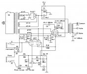
I have an old Masco C-10 Amp I was trying to get going. I've tried reforming the caps and I've replaced the burnt tubes (specifically the twin diode rectifier tube). I was getting a good output but the transformer was heating up. So I then replaced the multi-cap can with some individual capacitors. Still heating up. I then drew out the schematic and noticed the 20k ceramic resistor going to ground. I had a look and it's on a two terminal block bolted to the chasis and the terminal has been busted off. It is now held in place with a wire to the adjacent terminal. It looks like to me this shouldn't be going to ground. Maybe someone with more knowlege than I can have a look at this circuit and tell me what they think.
Thanks,
Craig
Attachments
Hi,
I have an old Masco C-10 Amp I was trying to get going. I've tried reforming the caps and I've replaced the burnt tubes (specifically the twin diode rectifier tube). I was getting a good output but the transformer was heating up. So I then replaced the multi-cap can with some individual capacitors. Still heating up. I then drew out the schematic and noticed the 20k ceramic resistor going to ground. I had a look and it's on a two terminal block bolted to the chasis and the terminal has been busted off. It is now held in place with a wire to the adjacent terminal. It looks like to me this shouldn't be going to ground. Maybe someone with more knowlege than I can have a look at this circuit and tell me what they think.
Thanks,
Craig
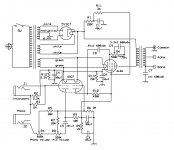
The 20K as shown would pull a lot of current that's why the transformer is heating up, a more reasonable schematic is shown below, perhaps the 20K is sub'd for the choke?
An externally hosted image should be here but it was not working when we last tested it.
Jaz
Last edited:
The 20K as shown would pull a lot of current that's why the transformer is heating up, a more reasonable schematic is shown below, perhaps the 20K is sub'd for the choke?
An externally hosted image should be here but it was not working when we last tested it.
Jaz
Right now, the center tap from the B+ transformer is going to chasis ground. Also it's using a multi-cap can, so no way to grab the negative of the 10uf/20uf cap. Do you think the center tap should be going to this resistor?
Well, it's been around since I was a kid, so partly just want to get it going. Will use it for guitar. Wasn't looking for a guess... was hoping this would be a familiar circuit to someone.
Check out the Fender 5C1 Champ, or even other Masco for inspiration. Harp players seem really into the classic Masco's for their tone.
- Status
- This old topic is closed. If you want to reopen this topic, contact a moderator using the "Report Post" button.
- Home
- Amplifiers
- Tubes / Valves
- Masco C-10 Mic/Phono Amp