Hi Merlin,
I repeated the experiment with much better layout and found the output impedance at 1kHz was approximately 3400 Ohms. Positive numbers this time!
Bondini
Thanks Bondini,
So mandatory the OPT to reduce the output impedance to match headphones impedance.
Best
Felipe

Hi Tubelab,
Thanks for taking a constructive approach and for putting in so much effort. I appreciate the time you have taken to explore the idea
I already had an amp wired up and being tested, so it was an easy and informative task for me. It led to me digging up some long forgotten small OPT's and testing them for use with headphones. Next I will try the same experiment with 300B tubes to see if their lower plate resistance can squeeze a bit more low end response....not that it'e really needed, I doubt the even the "DJ" headphones really have much response at 18 Hz.
Extra power due energy storage can only be used in musical regime, for short transients, because distortion is high.
The plate voltage will rise well above the B+ voltage even with a sine wave at low distortion. This is due to the stored energy in the OPT's core being released.......
The plate voltage will swing from the saturation voltage of the tube to twice B+ or beyond, if lightly loaded (32 ohm load on a 5K to 8 ohm OPT).
It does NOT happen when the plate is tied to B+ (for AC) through a 32 ohm resistor. With a 32 ohm shunt across the OPT, the plate voltage moves by a volt or so at most, while the current COULD vary from near zero to well beyond twice the idle current, limited by the emission characteristics of the tube and how it's driven. Of course this will be a highly non symmetrical and distorted waveform. I saw this yesterday during testing (my amp can, and did drive the grid positive (A2) but most of my tubes saturate before the grid got out of the negative side of the curve, especially into a near vertical load line.
All of my 45 tubes are old, and were obtained used on Ebay back when you could get them for $5 each (over 20 years ago). I built a class AB2 push pull amp years ago that should make over 20 watts per channel, but only a few of my tubes could meet the peak emission demands, so I wound up using NOS triode wired 307A's which made over 30 WPC on a higher B+ voltage.
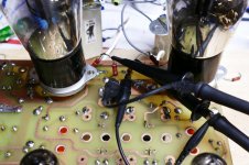
I'm including 3 pictures. The first shows a voltage divider wired from plate to ground of each channel to prevent blowing up my scope from high plate voltage. The scope was then adjusted with the aid of a DC voltmeter such that each vertical division represents 100 volts, with zero volts at the bottom of the screen and 500 volts in the center. Each of the two channels is connected to one of the output tube plates.
Both channels were driven from the audio oscillator at 1KHz. One channel was loaded with the OPT which has 33 ohms across it's 8 ohm secondary (roughly a 20 K load). This output feeds the audio analyzer for THD and power output readings.
The other channel feeds the same OPT with it's secondary unloaded, but the 100 uF cap in series with 33 ohms is tied across the primary (parafeed OTL).
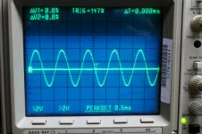
The second picture shows the plate voltages with the input turned up such that the lightly loaded channel is making about 1 watt of output power and it's THD was in the 1% range. It's plate voltage swings from about 200 volts to almost 500 volts. The "32 ohm" channel is stuck near 340 volts (B+). It is moving up and down by several hundred millivolts, but that's not visible at 100 volts per box on the scope.
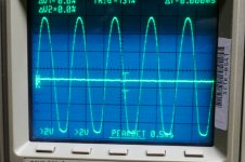
The third picture shows what happens when I cranked it up until the THD on the lightly loaded channel reads 5%. Here the tube has its grid driven about 20 volts positive, but has exhausted its emission capability and can't yank it's plate any lower than about 40 volts. This is called saturation. 40 volts is GOOD for a 45 or ANY DHT, and is possible only because of the light 20K ohm load. Most 45's can barely hit 70 volts into a 5K ohm OPT. The plate voltage hits almost 800 volts on it's positive swing......The B+ is 340 volts, so the positive swing is MORE than 2 X B+.
Note that the audio analyzer was reading 3.7 watts into 33 ohms. I doubt that this was accurate since my load resistors were smoking at the time and likely weren't (3 X) 100 ohms any longer.
Whether bondini's amp makes 20 mW or 20 watts it doesn't matter as long as he is happy with it. He has bought some OPT's that are quite similar to those that I used yesterday, and if his results are anywhere near mine, he will be pleased. Meanwhile, I thing I'm going to plug the Sennheisers in and crank it up!
Attachments
The plate voltage will rise well above the B+ voltage even with a sine wave at low distortion. This is due to the stored energy in the OPT's core being released.......
Agreed. As I said it's linearity the principal cause of distortion that sets the max continuous power.
I don't think one can argue against he Radiotron formula I posted earlier. With a vertical loadline in the best case things will be the same as in a typical application with a load 2-4 times the plate resistance but most of the times it will be worse. Impossible to get 20mW into 32R with 0.04% at 20 mA quiescent current with any triode in SE common cathode. Even if new. 5% is already optimistic. I have 3 quads of new 45's and they are no exception.
That's all. Then what one likes or not does not touch me. Discussions on subjective preferences are hopeless. I also said that he can use it anyway with the Audio Technica because they are very sensitive and with 1 mW already produce over 100 dB SPL.
Last edited:
I don't think one can argue against he Radiotron formula I posted earlier.
I can argue against the formula because it is wrong
eta = RL[2RL + 4ra]
The correct one
η = RL / (2RL + 4ra)
A very inopportune typo

Last edited:
In a quest to find out if this concept was valid at all (remember the OTL for guitar thread that blew up) I stuffed some 2A3's in the amp and tried again. Again, better but the amp was obviously starved for current, so what to do but turn it up!
Actually why don't you try with a CCS in place of the anode choke and see how it compares? At least energy storage is ruled out.
According to Radiotron anode efficiency of the 2A3 would be about 1%.
Actually why don't you try with a CCS in place of the anode choke
Been there, built that. A CCS will work very well in place of the anode choke IF you increase the B+ voltage on the CCS to accommodate plate voltage swings up to twice the original B+ voltage. In this case The B+ would be in the 600 to 700 volt range. I have a 650 volt supply and some 10M90 chips (900 volts at up to 100 mA) so I may try a CCS parafeed at some point, but I need to wrap up the TSE-II board redesign and get the boards ordered before wandering down any more side roads.
Some experiments here:
Active Loaded SE Output Stages | Tubelab
I use a CCS loaded 45 to drive 845's in A2 to 30 WPC here. See the third schematic on the page.
845 SE | Tubelab
Yes George I have read about your experiments that's why I asked. I know you are always trying stuff. In this case though, with the 32R headphone load (no output transformer), the voltage swing is small. Not much difference in comparison to the the choke, I guess.
Last edited:
Does about 3mJ worth the effort?
Juan it's just for looking at things comprehensively and actually a CCS might be even cheaper than a choke if one really wants to do it.
Meanwhile, I think I'm going to plug the Sennheisers in and crank it up!
Now THAT'S and idea!!
Bondini
Hi TheGimp,
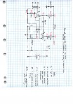
I've tidied up the schematic to show the 32 Ohm load and the sealed lead acid battery that powers the filaments. This shows more clearly that the base of the type 30's cathode bias resistor and the top of the 6A4/LA's cathode bias resistor share the negative terminal of the battery. Similarly, the positive battery terminal is shared by filament heater pin 1 of both valves.
This arrangement was very much a matter of convenience (I was experimenting, running through several topologies, didn't want to build heater supplies, was relying on the only battery I had, a 6.3V SLA) and serendipity (hey, maybe this will introduce a bit of negative feedback via the cathodes?). As you can see from the measured output, it's below the 1V rms input for a circuit that could probably deliver open loop voltage gain of around 50, so there is probably a bit of feedback lowering the gain and the distortion.
Attachments
I wouldn't go for the 4P1L myself. After using it for many years you will suffer with it due to its microphonic noise. You are better off with the 2P29L. It sounds as good and has no microphonic noise at all. It's dead easy to implement in filament bias as it only needs 120mA
Hi Ale. The years roll by and I wonder with your curiosity and experiments if you have updated advice for a DHT headamp these days?
I can't answer for Ale but I agree the 2P29L is a useful choice - lowish Ri at around 3K. For pure sound I'd use a 10Y. But a 6B4G/6C4C or a 2a3 has a really low Ri like 800 ohms, so less step-down. Better sound than a 2P29L. If you need more gain put a Hammond 1140-LN-C SUT in front in 1:4. That's what I use in front of my 10Y stage as a driver for my 2a3 outputs. More transparent than a second tube stage. I don't use headphones except for monitoring so just speaking generally. But certainly use a DHT.Hi Ale. The years roll by and I wonder with your curiosity and experiments if you have updated advice for a DHT headamp these days?
Someof the asking prices on the 10Y are getting ridiculousFor pure sound I'd use a 10Y. But a 6B4G/6C4C or a 2a3 has a really low Ri like 800 ohms, so less step-down.
and Sowter iron doesn't come cheap either:
A DIY budget friendly option might be less ultimate in sound but more pragmatic.How about:
You can get a 10Y for around £100-125. That's a representative price. Sowter is always expensive and there are much cheaper options. When I built a headphone amp I used Lundahl LL1689, but there are cheaper still. A 2P29L is good but a 6C4C is better, which you can buy from Ukraine and other ex-Soviet countries, Svetlana quality. Or a 6B4G if you're in the USA. And use Rod Coleman V9 filament regs. Or a Chinese 2a3 with AC heating and a hum pot.
- Home
- Amplifiers
- Tubes / Valves
- The all DHT SET Headphone Amp